
SFC Alpha-One
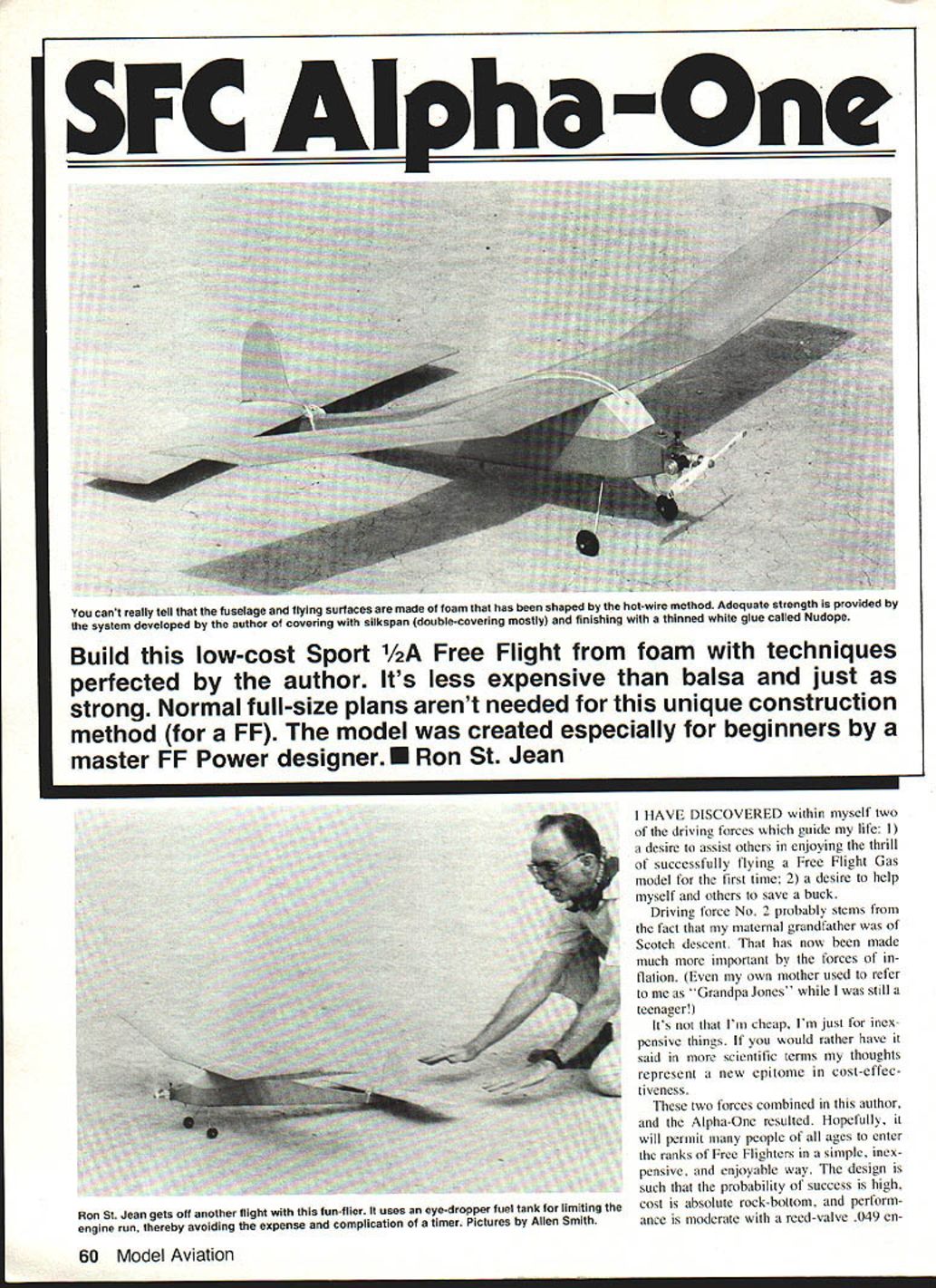
Build this low-cost Sport 1/2A Free Flight from foam with techniques perfected by the author. It's less expensive than balsa and just as strong. Normal full-size plans aren't needed for this unique construction method (for a FF). The model was created especially for beginners by a master FF Power designer. Ron St. Jean
I have discovered within myself two of the driving forces which guide my life: 1) a desire to assist others in enjoying the thrill of successfully flying a Free Flight gas model for the first time; 2) a desire to help myself and others to save a buck.
Driving force No. 2 probably stems from the fact that my maternal grandfather was of Scotch descent. That has now been made much more important by the forces of inflation. (Even my own mother used to refer to me as "Grandpa Jones" while I was still a teenager!)
It's not that I'm cheap, I'm just for inexpensive things. If you would rather have it said in more scientific terms my thoughts represent a new epitome in cost-effectiveness.
These two forces combined in this author, and the Alpha-One resulted. Hopefully, it will permit many people of all ages to enter the ranks of Free Flighters in a simple, inexpensive, and enjoyable way. The design is such that the probability of success is high, cost is absolute rock-bottom, and performance is moderate with a reed-valve .049 engine.
A friend suggested that the model would have more appeal if it looked like a real airplane, so it was made that way, complete with a tail-dragging landing gear. The original ship was fully adjusted on the third flight, and it was almost lost when it flew into an unanticipated thermal for 15 or 20 minutes! The second model flew right off the board, too.
New enjoyment is being found in these slow-climbing FFs. Perhaps flying them is more fun because you get to watch them climb longer, and they look more like real planes in flight. Once transitioned to glide, they thermal just as well as anything else. I would guess that much of the added enjoyment is also due to the reduced risks and to the fact that, when a ship is lost, one does not lose as much in terms of dollars.
And with the SFC (Structureless Foam Composites) construction, replacement time and effort are also at minimums.
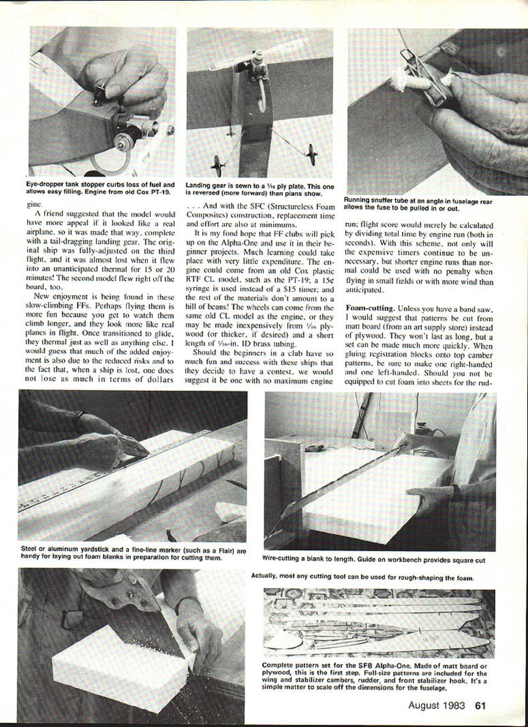
It is my fond hope that FF clubs will pick up on the Alpha-One and use it in their beginner projects. Much learning could take place with very little expenditure. The engine could come from an old Cox plastic RTF CL model, such as the PT-19; a 15¢ syringe is used instead of a $15 timer, and the rest of the materials don't amount to a hill of beans! The wheels can come from the same old CL model as the engine, or they may be made inexpensively from 1/16 plywood (or thicker, if desired) and a short length of 1/16-in. ID brass tubing.
Should the beginners in a club have so much fun and success with these ships that they decide to have a contest, we would suggest it be one with no maximum engine run; flight score would merely be calculated by dividing total time by engine run (both in seconds). With this scheme, not only will the expensive timers continue to be unnecessary, but shorter engine runs than normal could be used with no penalty when flying in small fields or with more wind than anticipated.
Foam-cutting
- Unless you have a band saw, I suggest that patterns be cut from matt board (from an art supply store) instead of plywood. They won't last as long, but a set can be made much more quickly.
- When gluing registration blocks onto top camber patterns, be sure to make one right-handed and one left-handed.
- Should you not be equipped to cut foam into sheets for the rudder, 1/16 balsa may be substituted for the 1/8-in. foam.
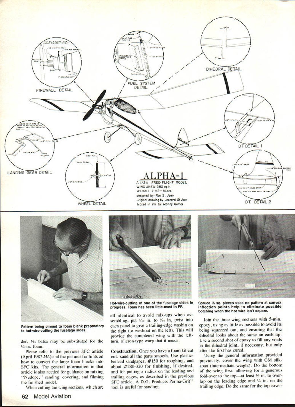
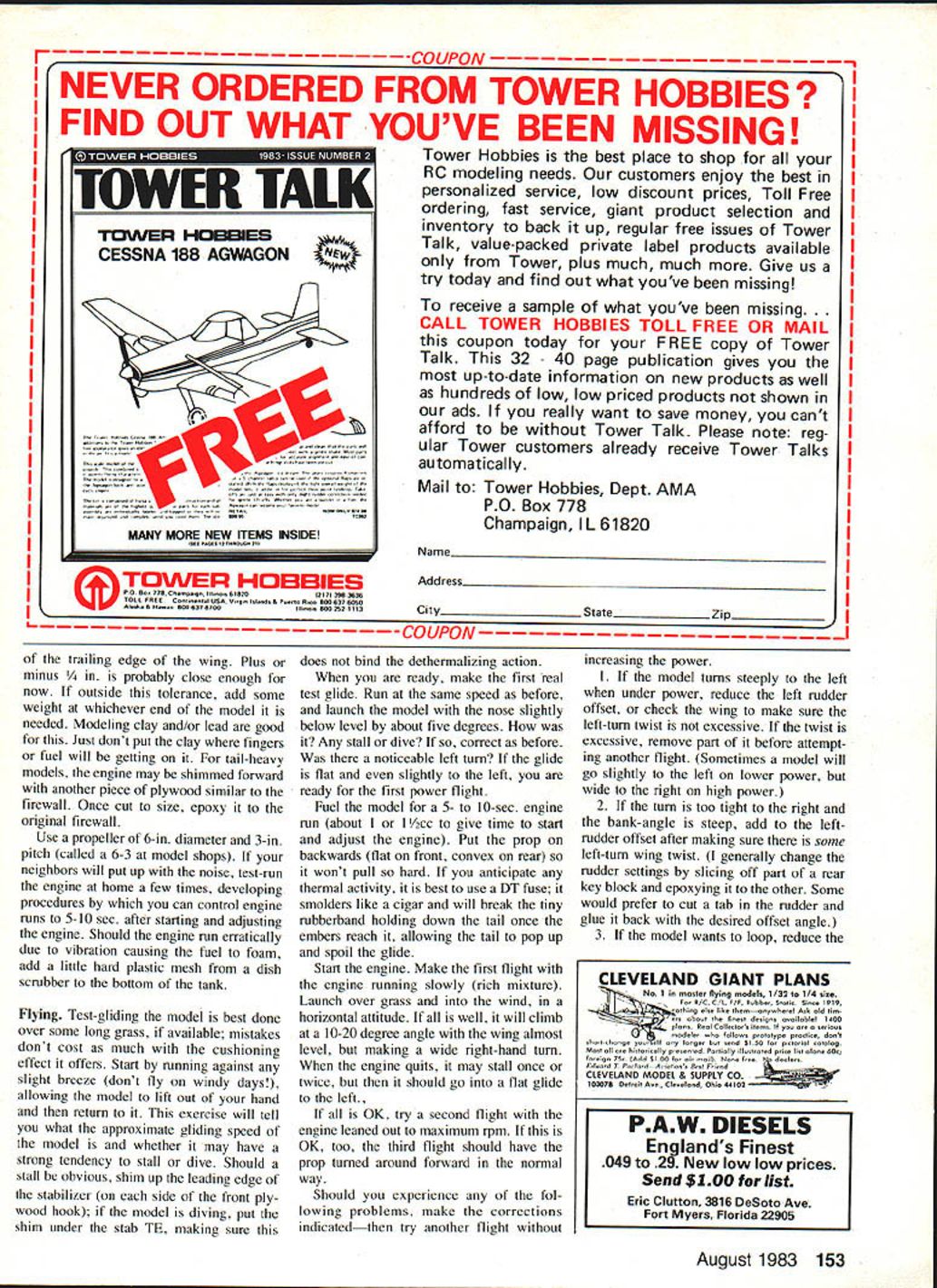
Please refer to the previous SFC article (April 1982 MA) and the pictures for hints on how to convert the large foam blocks into SFC kits. The general information in that article is also needed for guidance on mixing "Nudope," sanding, covering, and finishing the finished model.
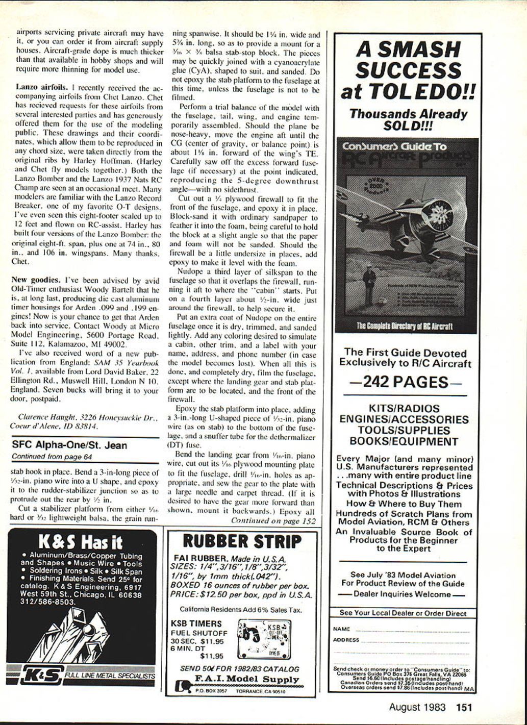
When cutting the wing sections, which are all identical to avoid mix-ups when assembling, put 1/2 in. to 3/8 in. twist into each panel to give a trailing-edge washin on the right (or washout on the left). This will provide the completed wing with the left-turn, aileron-type warp that it needs.
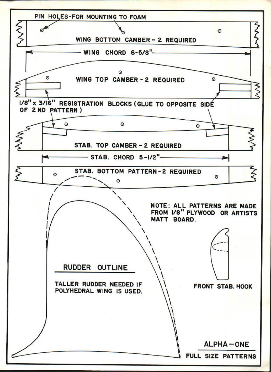
PIN HOLES - FOR MOUNTING TO FOAM
WING BOTTOM CAMBER - 2 REQUIRED
WING CHORD 6-5/8"
WING TOP CAMBER - 2 REQUIRED
1/8" x 3/16" REGISTRATION BLOCKS (GLUE TO OPPOSITE SIDE OF 2ND PATTERN)
STAB. TOP CAMBER - 2 REQUIRED
STAB. CHORD 5-1/2"
STAB. BOTTOM PATTERN - 2 REQUIRED
NOTE: ALL PATTERNS ARE MADE FROM 1/8" PLYWOOD OR ARTISTS MATT BOARD.
RUDDER OUTLINE
TALLER RUDDER NEEDED IF POLYHEDRAL WING IS USED.
FRONT STAB. HOOK
Construction
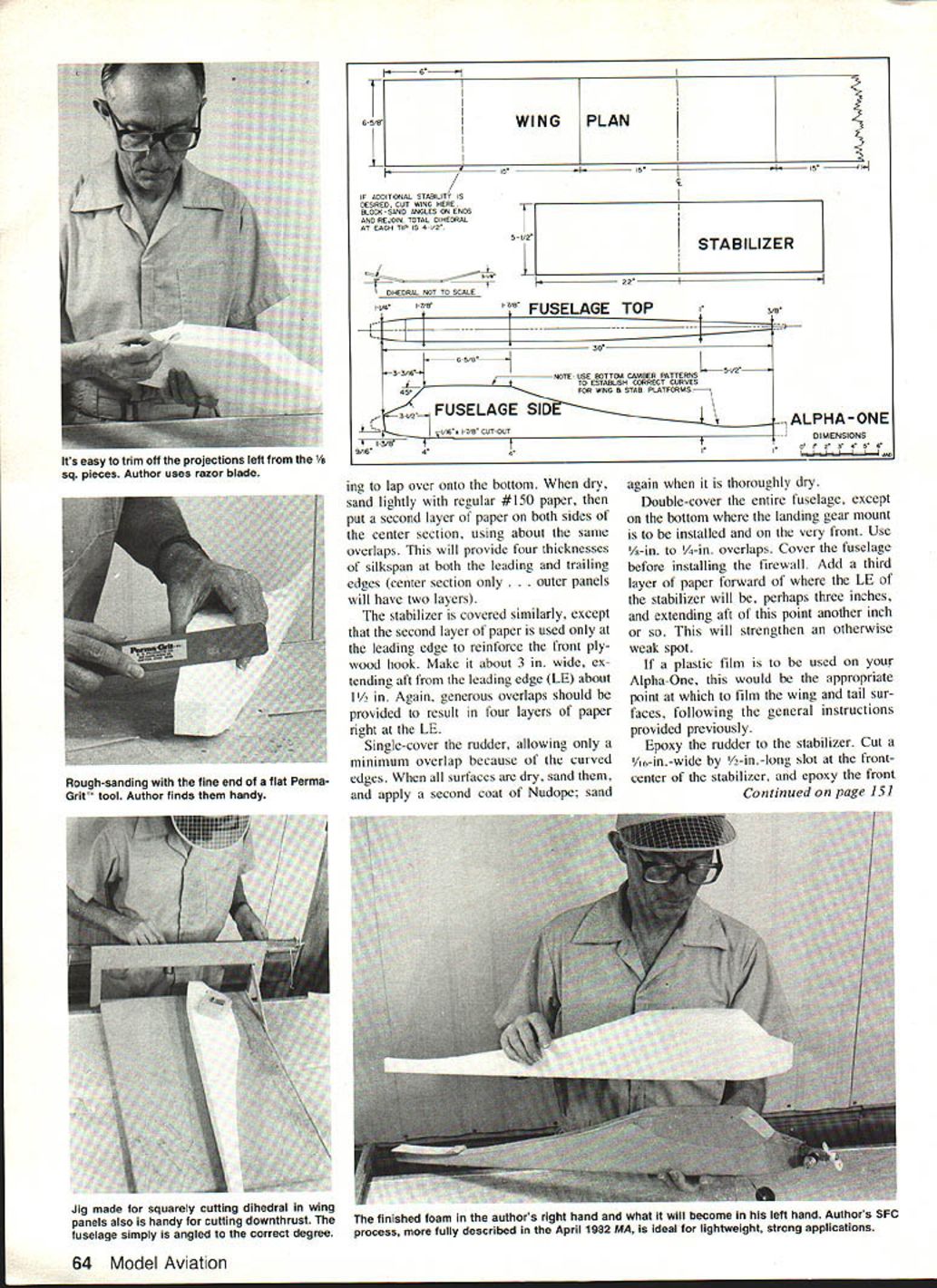
Once you have a foam kit cut out, sand all the parts smooth. Use plastic-backed sandpaper, #150 for roughing, and about #280–320 for finishing, if desired, and for putting a radius on the leading and trailing edges, as described in the previous SFC article. A D.G. Products Perma-Grit tool is useful for sanding.
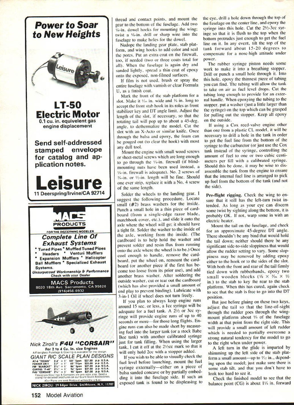
Join the three wing sections with 5-minute epoxy, using as little as possible to avoid its being squeezed out, and ensuring that the dihedral looks about the same on each tip. Use a second shot of epoxy to fill any voids in the dihedral joint, if necessary, but only after the first has cured.
Using the general information provided previously, cover the wing with GM silkspan (intermediate weight). Do the bottom of the wing first, allowing for a generous fold-over to the top — at least 1/2 in. overlap on the leading edge and 1/4 in. on the trailing edge. Do the same for the top cover.
When dry, sand lightly with regular #150 paper, then put a second layer of paper on both sides of the center section, using about the same overlaps. This will provide four thicknesses of silkspan at both the leading and trailing edges (center section only — outer panels will have two layers).
The stabilizer is covered similarly, except that the second layer of paper is used only at the leading edge to reinforce the front plywood hook. Make it about 3 in. wide, extending aft from the leading edge about 1-1/2 in. Again, generous overlaps should be provided to result in four layers of paper right at the LE.
Single-cover the rudder, allowing only a minimum overlap because of the curved edges. When all surfaces are dry, sand them, and apply a second coat of Nudope; sand again when it is thoroughly dry.
Double-cover the entire fuselage, except on the bottom where the landing gear mount is to be installed and on the very front. Use 3/8-in. to 1/4-in. overlaps. Cover the fuselage before installing the firewall. Add a third layer of paper forward of where the LE of the stabilizer will be, perhaps three inches, and extending aft of this point another inch or so. This will strengthen an otherwise weak spot.
If a plastic film is to be used on your Alpha-One, this would be the appropriate point at which to film the wing and tail surfaces, following the general instructions provided previously.
Epoxy the rudder to the stabilizer. Cut a 1/16-in.-wide by 1/2-in.-long slot at the front-center of the stabilizer, and epoxy the front stab hook in place. Bend a 3-in.-long piece of 1/32-in. piano wire into a U shape, and epoxy it to the rudder-stabilizer junction so as to protrude out the rear by 1/8 in.
Cut a stabilizer platform from either 1/8-in. hard or 3/32-in. lightweight balsa, the grain running spanwise. It should be 1-1/4 in. wide and 5-5/8 in. long, so as to provide a mount for a 3/8 x 3/8 balsa stab-stop block. The pieces may be quickly joined with a cyanoacrylate glue (CyA), shaped to suit, and sanded. Do not epoxy the stab platform to the fuselage at this time, unless the fuselage is not to be filmed.
Perform a trial balance of the model with the fuselage, tail, wing, and engine temporarily assembled. Should the plane be nose-heavy, move the engine aft until the CG (center of gravity, or balance point) is about 1-1/8 in. forward of the wing's trailing edge. Carefully saw off the excess forward fuselage (if necessary) at the point indicated, reproducing the 5-degree downthrust angle — with no sidethrust.
Cut out a 1/4-in. plywood firewall to fit the front of the fuselage, and epoxy it in place. Block-sand it with ordinary sandpaper to feather it into the foam, being careful to hold the block at a slight angle so that the paper and foam will not be sanded. Should the firewall be a little undersize in places, add epoxy to make it level with the foam.
Nudope a third layer of silkspan to the fuselage so that it overlaps the firewall, running it aft to where the "cabin" starts. Put on a fourth layer about 1/2 in. wide just around the firewall, to help secure it.
Put an extra coat of Nudope on the entire fuselage once it is dry, trimmed, and sanded lightly. Add any coloring desired to simulate a cabin, other trim, and a label with your name, address, and phone number (in case the model becomes lost). When all this is done, and completely dry, film the fuselage, except where the landing gear and stab platform are to be located, and the front of the firewall.
Epoxy the stab platform into place, adding a 3-in.-long U-shaped piece of 1/32-in. piano wire (as on stab) to the bottom of the fuselage, and a snuffer tube for the dethermalizer (DT) fuse.
Bend the landing gear from 1/16-in. piano wire, cut out its 1/16-in. plywood mounting plate to fit the fuselage, drill 1/16-in. holes as appropriate, and sew the gear to the plate with a large needle and carpet thread. (If it is desired to have the gear move forward than shown, mount it backwards.) Epoxy all contact points, and mount the gear to the bottom of the fuselage. Add two 5/8-in. dowel hooks for mounting the wing; twist a 1/8-in. drill or sharp wire into the fuselage to make holes for the dowel.
Nudope the landing gear plate, stab platform, and wing hooks to add color and seal the pores. Put an extra coat on the firewall, too, if needed (two or three coats total for all). When the fuselage is again dry and sanded lightly, spread a thin coat of epoxy onto the exposed, non-filmed surfaces.
If film is not used, brush or spray the entire fuselage with varnish or clear Formula U, as a finish coat.
Mark the front of the stab platform for a slot. Make it 1/8 in. wide and 3/8 in. long to accept the front stab hook in its role as front stabilizer key and DT angle limit. Adjust the length of the slot, if necessary, so that the rotating tail will pop up to about a 45-degree angle, to dethermalize the model. Cut the slot with an X-Acto or similar knife. Once through the balsa and epoxy, the foam can be gouged out (to clear the hook) with most any dull tool.
Mount the engine with small wood screws or sheet-metal screws which are long enough to go through the 1/8-in. firewall (if blind-mounting nuts have been used instead, a 1/8-in. firewall is adequate). No. 2 screws of 5/16-in. or 3/8-in. length will be fine. Should one ever strip, replace it with a No. 4 screw of the same length.
Solder the wheels to the landing gear. Suggested procedure:
- Locate small (#2) brass washers for the inside.
- Punch a small hole in a thin piece of cardboard (from a single-edge razor blade cover, matchbook cover, etc.), and slide it onto the axle where the wheel will go; it should have a tight fit.
- Solder the washer to the inside of the axle, working from the inside. (The cardboard helps hold the washer and prevent solder and flux from running onto the axle where the wheel is to be.)
- Once cool enough to handle, remove the cardboard, put the wheel on, remount the cardboard (or another piece), and add another brass washer.
- After soldering the outside washer, cut or tear out the cardboard (which has also provided a small amount of end play to prevent binding). Lubricate with 3-in-1 oil if wheel does not turn freely.
If you plan to always keep engine runs around 15 sec. or less, a 1-cc syringe will be adequate for a fuel tank. A 2-1/2 or 3-cc syringe will provide engine runs of up to 40 seconds or more—for those long flights. Engine runs can also be made short by measuring fuel into the larger tank (or a stock Babe Bee tank) with another calibrated syringe just for tank filling. When using the larger tank, I cut it off at the 2-cc mark so that it will only hold 2 cc with a stopper added.
If you wish to be able to visually check the fuel level before launching, mount the fuel syringe externally—either on a piece of balsa sanded concave or by partially embedding it into the fuselage side. If such an exposed tank is found to be displeasing to the eye, drill a hole down through the top of the fuselage on the center line, and epoxy the syringe into this hole. Cut the 2-1/2–3-cc syringe so that it is flush to the top when the bottom protrudes just enough to get the fuel line on it. In any event, tilt the top of the tank forward about 15–20 degrees to compensate for a nose-high attitude under power.
The rubber syringe piston needs some work to make it into a breathing stopper. Drill or punch a small hole through it. Into this hole, epoxy the thinnest piece of tubing you can find. The tubing will allow the tank to take on air as fuel level drops. Cut the tubing long enough to provide for an external handle. When epoxying the tubing to the stopper, put a washer (just a little larger than the syringe) on the top which can be grasped for pulling out the stopper. Keep all epoxy on the outside.
If using a Cox reed-valve engine other than one from a plastic CL model, it will be necessary to drill a hole in the tank in order to get the fuel line from the bottom of the syringe to the carburetor (or just use the Cox tank instead of the syringe, controlling the amount of fuel to one or two cubic centimeters per fill with a calibrated syringe). Should this be done, it may be wise to disassemble the tank from the engine to ensure that the internal fuel line is arranged to pick up fuel from the bottom of the tank (and not the side).
Pre-flight rigging
- Check the wing to ensure that it still has the left-turn twist intended. As long as your eye can discern some twist by sighting along the bottom, it is probably OK. If not, warp some in with an electric heater.
- Mount the tail on the fuselage, and check for an approximate 45-degree DT angle. There shouldn't be any bind that would hold the tail down; neither should there be any significant side-to-side sloppiness that would allow the rudder setting to vary.
- Some sloppiness may be removed by adding epoxy either to the hook or to the sides of the slot. With both the front and rear of the tail firmly tied down with rubber bands, epoxy two small wooden blocks (1/4 x 1/4 x 1/2 in.) to the stab to key the rear to the stab platform. When this has cured, again check to see that the stab is free to go into the DT position.
- Just before gluing on these two keys, adjust the tail so that the line-of-sight through the rudder goes through the wing-mount platform about 1/3 of the fuselage width at that point from the right side. This will provide a small amount of left rudder which is needed to partially overcome a natural tendency for the model to go to the right when under power.
- A left turn in the glide is imparted by shimming up the left side of the stab platform a small amount—up to 1/32 in., depending on the model; just make sure there is some stab tilt, and that you don't have to look too hard to see it.
Check the finished model to see that the balance point (CG) is about 1 1/4 in. forward of the trailing edge of the wing. Plus or minus 1/4 in. is probably close enough for now. If outside this tolerance, add some weight at whichever end of the model it is needed. Modeling clay and/or lead are good for this. Just don't put the clay where fingers or fuel will be getting on it. For tail-heavy models, the engine may be shimmed forward with another piece of plywood similar to the firewall. Once cut to size, epoxy it to the original firewall.
Use a propeller of 6-in. diameter and 3-in. pitch (called a 6-3 at model shops). If your neighbors will put up with the noise, test-run the engine at home a few times, developing procedures by which you can control engine runs to 5–10 sec. after starting and adjusting the engine. Should the engine run erratically due to vibration causing the fuel to foam, add a little hard plastic mesh from a dish scrubber to the bottom of the tank.
Flying
Test-gliding the model is best done over some long grass, if available; mistakes don't cost as much with the cushioning effect it offers. Start by running against any slight breeze (don't fly on windy days!), allowing the model to lift out of your hand and then return to it. This exercise will tell you what the approximate gliding speed of the model is and whether it may have a strong tendency to stall or dive. Should a stall be obvious, shim up the leading edge of the stabilizer (on each side of the front plywood hook); if the model is diving, put the shim under the stab trailing edge, making sure this does not bind the dethermalizing action.
When you are ready, make the first real test glide. Run at the same speed as before, and launch the model with the nose slightly below level by about five degrees. Any stall or dive? If so, correct as before. Was there a noticeable left turn? If the glide is flat and even slightly to the left, you are ready for the first power flight.
Fuel the model for a 5- to 10-sec. engine run (about 1 or 1/2 cc to give time to start and adjust the engine). Put the prop on backwards (flat on front, convex on rear) so it won't pull so hard. If you anticipate any thermal activity, it is best to use a DT fuse; it smolders like a cigar and will break the tiny rubber band holding down the tail once the embers reach it, allowing the tail to pop up and spoil the glide.
Start the engine. Make the first flight with the engine running slowly (rich mixture). Launch over grass and into the wind, in a horizontal attitude. If all is well, it will climb at a 10–20 degree angle with the wing almost level, but making a wide right-hand turn. When the engine quits, it may stall once or twice, but then it should go into a flat glide to the left.
If all is OK, try a second flight with the engine leaned out to maximum rpm. If this is OK, too, the third flight should have the prop turned around forward in the normal way.
Troubleshooting
Should you experience any of the following problems, make the corrections indicated—then try another flight without increasing the power.
- If the model turns steeply to the left when under power, reduce the left rudder offset, or check the wing to make sure the left-turn twist is not excessive. If the twist is excessive, remove part of it before attempting another flight. (Sometimes a model will go slightly to the left on lower power, but wide to the right on high power.)
- If the turn is too tight to the right and the bank-angle is steep, add to the left-rudder offset after making sure there is some left-turn wing twist. (I generally change the rudder settings by slicing off part of a rear key block and epoxying it to the other. Some would prefer to cut a tab in the rudder and glue it back with the desired offset angle.)
- If the model wants to loop, reduce the incidence by raising the front of the stabilizer; add weight to the rear of the model to prevent diving in the glide. Test-glide again to confirm that the changes have not adversely affected the glide. It may also be necessary to add more downthrust.
- If the model dives in under power or falls like an arrow in the glide, incidence must be increased by raising the rear of the stabilizer. At the same time, add weight to the nose of the plane to eliminate any glide stall. Should the problem occur when under power only, reducing the amount of downthrust may be the answer.
- If the power pattern is OK but the glide circle is too wide, shim up the left side of the stab some more—the same amount at the front and back so as not to change the incidence setting. Should the ship appear to be spiraling in during the glide phase of the flight, widen the circle by removing some of the shims. (Don't confuse this, however, with the lack of incidence described in Problem 4.)
Although other patterns may work for some, most modern models will be the safest and most stable when flown to the right under power and to the left in the glide (right/left pattern).
Should you experience some difficulty or problem not covered here or in the previous SFC article, please feel free to direct your questions to the author. Every effort will be made to help.
Ordering and Contacts
If you would like to try an SFC Alpha-One before getting equipped to cut foam yourself, I will provide foam-only kits for $18 each, plus $3.00 for shipping. In this way, you can prove to yourself that SFC is the way to go before having to make the time and investment required to cut your own foam. Good luck!
Ron St. Jean 3744 E. Nye Lane Carson City, NV 89701 Telephone: (702) 883-2400
(Editor: You may obtain photocopies of Ron St. Jean's Structureless Foam Composites article from the April 1982 issue for $1.00—check or money order, please—from Model Aviation, 1810 Samuel Morse Dr., Reston, VA 22090.)
It appears there was a little confusion on the availability of plans and engine work from Tom Dixon. You can contact him at:
Controlaire Sales Tom Dixon P.O. Box 27540, Contract Station #7 Atlanta, GA 30327
He has added the following plans to his list: El Diablo (by Red Reinhardt), the Baby Barnstormer (Guillow kit), Tom-Tom and Warrior (Veco kits), Gobblesentz (Charlie Mackey), Argus (Steve Woolley, from his own plans), Oriental 40 (similar to the .35-size, but scaled up for .40–.46 engines). Tom recently said that he has filled several orders for his custom-bored Fox .35 stunt engines, so if you want a good .35 for the summer, contact him about the various stages of rework on his veteran engine.
Transcribed from original scans by AI. Minor OCR errors may remain.

