

SFC (Structureless Foam Composites)
Most of the world's balsa supply is being used in super-tanker construction, we're told. Balsa is still available, but this additional demand has forced the price up to the point where many of us feel we can no longer afford it. This writer, for instance, was appalled at the balsa price situation in 1978, when he discovered that it would cost $22.00 just to balsa-sheet an 8-foot glider wing!
Foam plastic has been coming into ever-greater use in model construction during the past few years, but current techniques are still quite costly because they involve the use of expensive surfacing materials—balsa, thin plywood, or a special film. Such approaches, in addition to being costly, are too heavy for several modeling applications, especially Free Flight.
What is needed is an inexpensive way of rigidizing foam plastic cores so as to add the needed strength without adding much weight, cost, or building time. We offer the results of our three years of research on these pages. What is presented is essentially a follow-up on the fine series of articles by Evans and Lester, appearing in the January–March, 1978 issues of MA.
— Ron St. Jean
Early research
The foam plastic we were experimenting with was the common variety of white expanded polystyrene (Styrofoam) sold in lumberyards for insulation. It comes in various thicknesses from 1 in. up, and is either 2- or 4-ft. wide by 8 ft. long. This material has a density of only one pound per cubic foot, and it is quite cheap.
One problem with this material is that the polystyrene foam is easily dissolved by most glue, dope and paint. We found, as others have, that the best compatible liquid materials are white glue and epoxy. In attempting to first seal the foam with white glue and then top-coat with dope, the result was that the dope usually managed to find or make a break in the seal, ruining the job by "eating up" most of the foam.
Early attempts assumed that structural rigidity required the use of a supporting wooden structure. Leading and trailing edges, spars, and some ribs were, therefore, added to the foam core. Besides being time-consuming and adding to weight and expense, such reinforcing structures were found to be totally unnecessary. Adequate rigidity, in almost all cases, can be achieved with the skin alone!
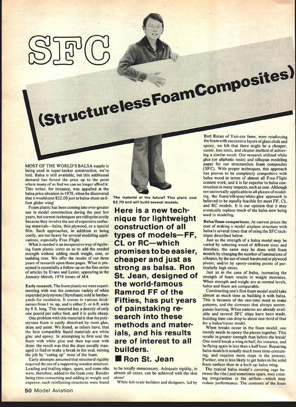
Here is a new technique for lightweight construction of all types of models—FF, CL or RC—which promises to be easier, cheaper and just as strong as balsa. Ron St. Jean, designer of the world-famous Ramrod FF of the Fifties, has put years of painstaking research into these methods and materials, and his results are of interest to all builders.
While full-scale builders and designers, led by Burt Rutan of Vari-Eze fame, were reinforcing the foam with successive layers of glass cloth and epoxy, we felt that there might be a cheaper, easier, less toxic, and cleaner method of achieving a similar result. Our research utilized white glue (or aliphatic resin) and silkspan modeling paper for our structureless foam composites (SFC). With proper techniques, this approach has proven to be completely competitive with balsa wood in terms of almost all Free-Flight contest work; and it is far superior to balsa construction in many respects, such as cost. Although not universally applicable to all phases of model construction, the foam/silkspan/white-glue approach is believed to be equally feasible for most FF, CL and RC models. It is our opinion that it may eventually replace much of the balsa now being used in modeling.
Balsa/foam comparisons
At current prices the cost of making a model airplane structure with balsa is several times that of using the SFC technique described below.
Just as the strength of a balsa model may be varied by selecting wood of different sizes and densities, the same may be done with foam models by changing the number of laminations of silkspan, by the use of small hardwood or plywood pieces, and/or by epoxy-coating points of particularly high stress.
Just as in the case of balsa, increasing the strength of foam results in weight increases. When strength and weight are at normal levels, balsa and foam are comparable.
Constructing one's first foam model could take almost as much time as building it with balsa. This is because of the one-time need to make patterns, and the slowness that always accompanies learning. When patterns are already available and several SFC ships have been made, building time can drop to about one-third that of a balsa/tissue model.
When breaks occur in the foam model, one merely needs to epoxy the pieces together. This results in greater strength than before the break! One could break a wing in half, for instance, and be flying again in less than a half hour. Repairing balsa models is usually much more time-consuming, and requires more steps in the process. Further, one is less likely to get holes in the solid foam surface than in a built-up balsa wing.
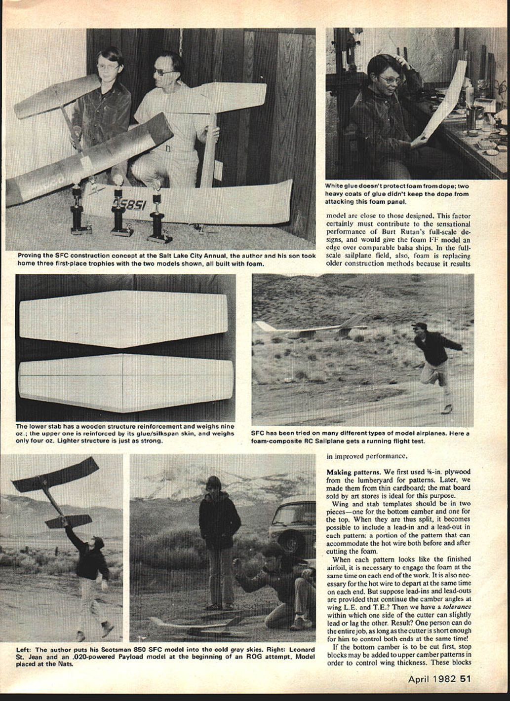
The typical balsa model's covering sags between the ribs (and sometimes spars, too), creating irregularities in the airflow—which may reduce performance. The contours of the foam model are close to those designed. This factor certainly must contribute to the sensational performance of Burt Rutan's full-scale designs, and would give the foam FF model an edge over comparable balsa ships. In the full-scale sailplane field, also, foam is replacing older construction methods because it results in improved performance.
Making patterns
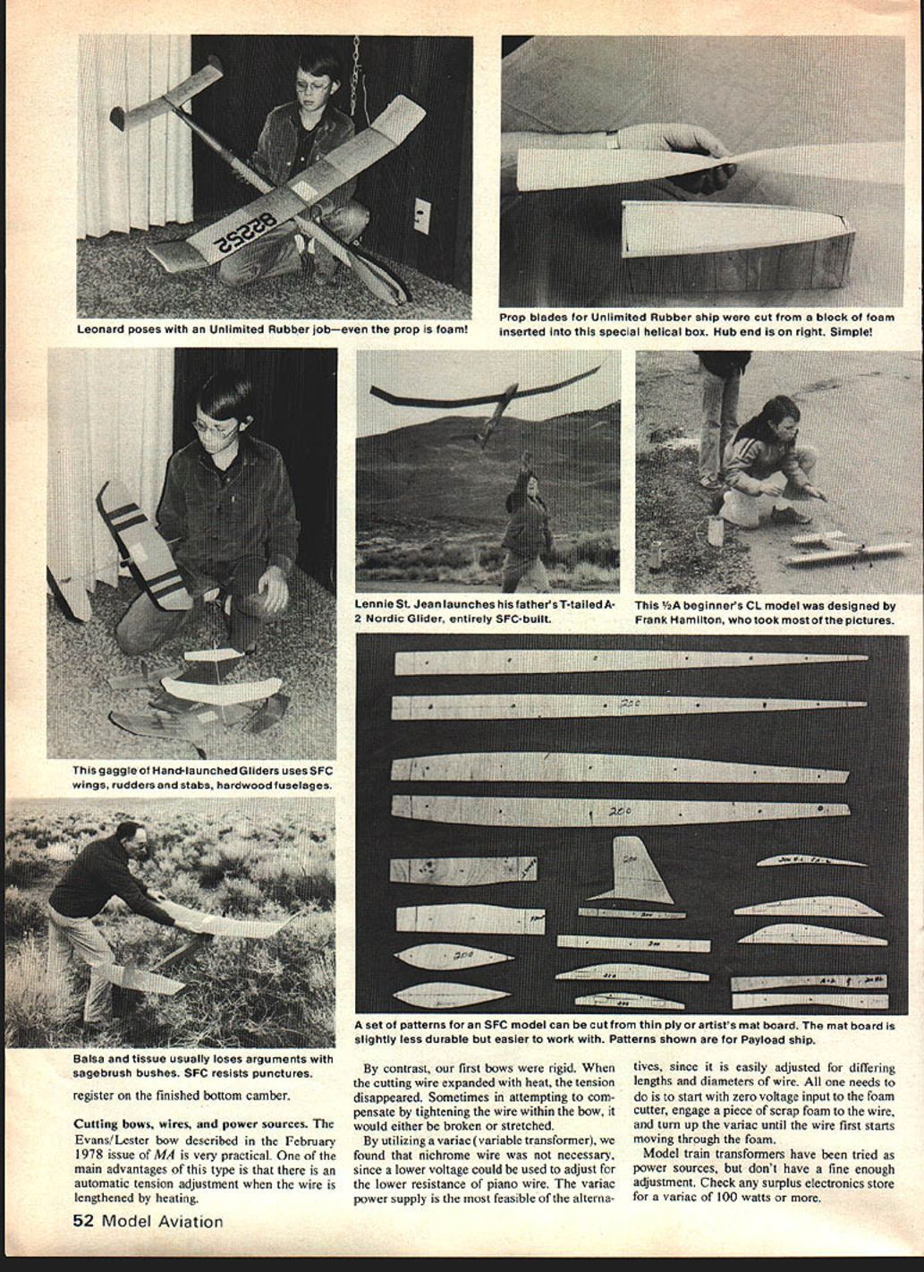
We first used 1/8-in. plywood from the lumberyard for patterns. Later, we made them from thin cardboard; the mat board sold by art stores is ideal for this purpose.
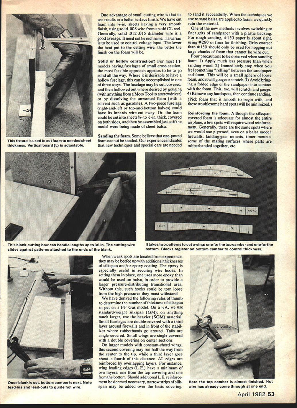
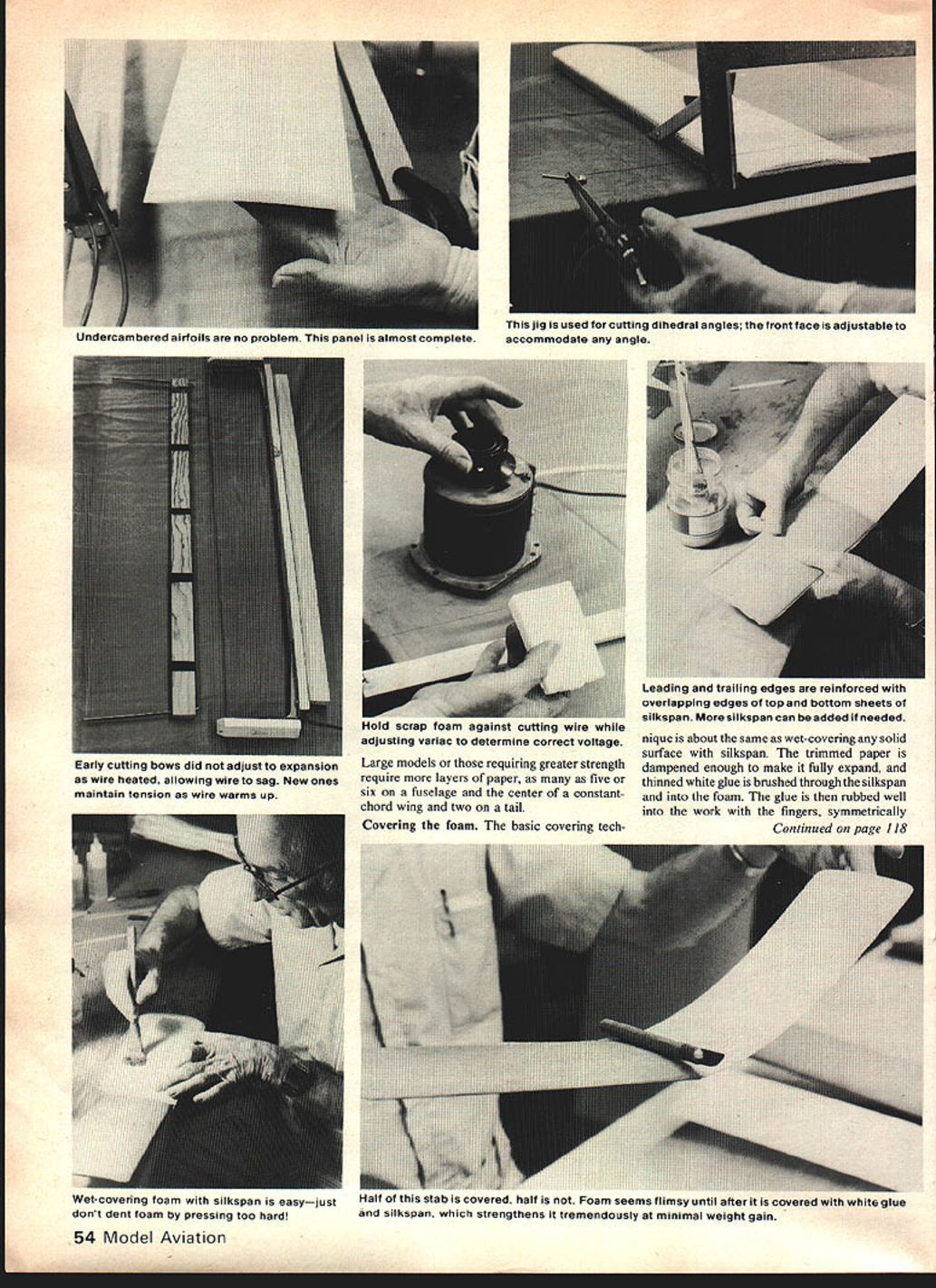
Wing and stab templates should be in two pieces—one for the bottom camber and one for the top. When they are thus split, it becomes possible to include a lead-in and a lead-out in each pattern; a portion of the pattern that can accommodate the hot wire both before and after cutting the foam.
When each pattern looks like the finished airfoil, it is necessary to engage the foam at the same time on each end of the work. It is also necessary for the hot wire to depart at the same time on each end. But suppose lead-ins and lead-outs are provided that continue the camber angles at wing L.E. and T.E.? Then we have a tolerance within which one side of the cutter can slightly lead or lag the other. Result? One person can do the entire job, as long as the cutter is short enough for him to control both ends at the same time!
If the bottom camber is to be cut first, stop blocks may be added to upper camber patterns in order to control wing thickness. These blocks register on the finished bottom camber.
Cutting bows, wires, and power sources
The Evans/Lester bow described in the February 1978 issue of MA is very practical. One of the main advantages of this type is that there is an automatic tension adjustment when the wire is lengthened by heating.
By contrast, our first bows were rigid. When the cutting wire expanded with heat, the tension disappeared. Sometimes in attempting to compensate by tightening the wire within the bow, it would either be broken or stretched.
By utilizing a variac (variable transformer), we found that nichrome wire was not necessary, since a lower voltage could be used to adjust for the lower resistance of piano wire. The variac power supply is the most feasible of the alternatives, since it is easily adjusted for differing lengths and diameters of wire. All one needs to do is to start with zero voltage input to the foam cutter, engage a piece of scrap foam to the wire, and turn up the variac until the wire first starts moving through the foam.
Model train transformers have been tried as power sources, but they don't have a fine enough adjustment. Check any surplus electronics store for a variac of 100 watts or more.
One advantage of small cutting wire is that its use results in a better surface finish. We have cut foam into 1/8-in. sheets having a very smooth finish, using solid .008 wire from an old C.L. reel. Generally, solid .012–.015 diameter wire is a good average. It need not be nichrome if a variac is to be used to control voltage input. The lower the heat put to the cutting wire, the better the finish on the foam will be.
Solid or hollow construction?
For most FF models having fuselages of small cross-section, the most feasible approach appears to be to go solid all the way. Where it is desirable to have a hollow fuselage, this can be accomplished in one of three ways:
- Cut the fuselage, cover it, and then hollow out where desired by gouging (with anything from a Moto-Tool to a screwdriver) or by dissolving the unwanted foam with a solvent such as gasoline.
- Make a two-piece fuselage (right-and-left or top-and-bottom halves) and wire-cut the innards away.
- Cut the foam into sheets 3/8- to 1/2-in. thick, cover both sides, and then assemble just as if the model were being made of sheet balsa.
Sanding the foam
Some believe that one-pound foam cannot be sanded. Our experience indicates that new techniques and special care are needed to sand it successfully. When the techniques we use to sand balsa are applied to foam, we quickly ruin the material.
One of the new methods involves switching to finer grits of sandpaper with a plastic backing. For rough sanding, #150 paper is about right, using #280 or finer for finishing. Grits coarser than #150 should only be used for hogging out large chunks of foam that cannot be wire cut.
Four precautions to be observed when sanding foam:
- Apply much less pressure than when sanding wood.
- Immediately stop when you feel something “rolling” between the sandpaper and foam. This will be a small sphere of loose foam, and it will gouge or scratch.
- Avoid bringing a folded edge of the sandpaper into contact with the foam. This, too, will scratch and gouge.
- Remove any hard spots, then continue sanding. (Pick foam that is smooth to begin with, and these troublesome hard spots will be minimized.)
Reinforcing the foam
Although the silkspan-covered foam is adequate for almost the entire airplane, a few spots will require wood reinforcement. Generally, these are the same spots where we would use plywood, even on a balsa model: firewalls, landing-gear mounts, timer mounts, some of the mating surfaces where parts are rubberbanded together, etc.
When weak spots are located from experience, they may be beefed up with additional thicknesses of silkspan and/or epoxy coating. The epoxy is especially useful in securing wire hooks. In setting them in place, one uses more epoxy than would be used on balsa, in order to provide a larger pressure-distributing transitional area. Without this, such hooks could be torn loose from the high pressures they must withstand.
We have derived the following rules of thumb to determine the number of thicknesses of silkspan to put on a FF Gas model:
- On a 1/2A, use standard-weight silkspan (GM); on anything much larger, use the heavier (SGM) material.
- Small fuselages are double-covered with a third layer around firewalls and in front of the stabilizer where rubberbands go around. Tails are single-covered.
- Small wings are single-covered, with a double covering on center sections.
- On larger models with constant-chord wings, the second covering may run half the way from the center to the tip, while a third layer goes about a fourth of this distance. All edges are reinforced by overlapping layers. For instance, wing leading edges (L.E.) have a minimum of two layers: one from the top covering and one from the bottom. If additional L.E. reinforcement is deemed necessary, narrow strips of silkspan may be added over the basic covering.
- Large models or those requiring greater strength may require as many as five or six layers on a fuselage and the center of a constant-chord wing, and two on a tail.
Covering the foam
The basic covering technique is about the same as wet-covering any solid surface with silkspan. The trimmed paper is dampened enough to make it fully expand, and thinned white glue is brushed through the silkspan and into the foam. The glue is then rubbed well into the work with the fingers, symmetrically from center to tips. The bottom of flat or undercambered wings should be covered first, in order to better preserve the airfoil design.
White glue is thinned to about 60% glue / 40% water, and food coloring dye added. The dye colors the work and identifies glue voids (spots with no color). Aliphatic resin is thinned 50/50. We refer to this mix as "Nudope." Since the covering shrinks upon drying, it is wise to either cover the opposite side shortly after the first is almost dry, or redampen and flatten it just before doing the second side, in order to minimize warpage of the final product.
Should you need to remove a warp (or add one as an adjustment) this can be easily accomplished with heat. An electric heater works fine—just be careful not to melt the foam. The structures do, however, have a memory which tends to show up on very hot days; so it is better to cut adjustments into the foam at the start where feasible.
The covered model is sanded with #150 regular paper before finishing or adding additional thicknesses of paper.
Final humidity-proof finish
The film used to finish the SFC model is inexpensive, can be purchased in a grocery store, is quite light at about 1/2-mil thickness, is easily and quickly applied, and is almost infinitely heat-shrinkable.
It is Saran Wrap—not the original product but a fairly new one called Freezing and Microwave Saran Wrap. Here are a few tips for putting it on.
Put a light coat of spray adhesive on the structure, covering as large an area as feasible in order to minimize overlaps and later masking to eliminate glue spray on the finished work. Because of the film's heat-shrinking ability, this can be the entire top of a polyhedral wing. Make sure adhesive is fully set up before adding Saran. 3M's #77 spray adhesive is adequate. Make certain that all of the solvent in the adhesive has evaporated before pressing the plastic in place. Once the film is in place, rub it into the work at edges and joints so as to secure it while heat-shrinking, which is best done with an ordinary 250-watt heat lamp. Just "paint" the heat onto the Saran, being sure to keep the lamp moving and no closer than is needed to shrink the film (four or five inches). When you get too close or tarry too long in one spot, the foam can melt a little.
While heat shrinking, it is a good idea to hold the film at the adjacent edge, pulling it away from the work. This will prevent its shrinking away from the edge and into the work. After an area is shrunk, it should be immediately burnished into the foam surface with a Kleenex while it is still not for permanent attachment. Any entrapped air can be gradually worked out. Finally, the Saran is trimmed with a new razor blade, and the edges are finished with a MonoKote iron at low heat.
If desired, the Saran film may be painted on the inside prior to application. Most any spray paint will work. It will then look like the expensive factory-painted and -glued Mylar films, at a small fraction of the cost. This "Scotch Monocoat" will exclude moisture even better than before painting.
Since the Saran Wrap is softer than Mylar, it does tend to get scuffed up a bit when making landings on a hard surface. When such spots turn up, they are easily repaired with a bit of 5-minute epoxy smeared on the bad spot, or you might instead put a piece of Mylar over the spot.
Conclusions
It seems ridiculous to believe that a piece of flimsy, highly-flexible, and easily-squashed piece of foam could be stiffened and given enough strength, with the addition of more paper and glue, to become a competitive model airplane. When one begins to cover a long, thin wing, for instance, his first thought in handling the delicate coat might be, "I might as well try to cover a wet noodle!" But once the foam has taken on its paper clothing, it undergoes a transformation not unlike the metamorphosis of David Banner turning into the Hulk.
They say, "The proof of the pudding is in the eating." What will such a model do in competition? To date, the foam fleet has won nine trophies in five contests, using first-generation hardware!
The SFC approach has now been used successfully on several types of FF models, including Hand-Launched Gliders, P-30, Coupe, and Unlimited Rubber models, A-1 Towline Gliders, catapult gliders, as well as all classes of AMA Gas from .020s through Class D. SFC is a natural for CL Combat wings. Of perhaps 45 models built so far, three were RC. There is tremendous potential here, also, especially in Quarter Scale.
A beginner's FF gas model using a reed-valve .049 has been built and successfully tested. It was almost lost on the third flight. It will be the subject of a follow-up article soon to appear in these pages.
We have recently discovered that the inherently-more-efficient tapered wings can be SFC-built with only a slight increase in time and effort. In addition, several layers of silkspan are not usually required to beef up the center; the thicker and wider airfoil does the job instead. This results in a lighter overall model which is more efficient as well.
After years of research, development, testing, and evaluation of SFC concepts and techniques, we are more convinced than ever that it could eventually all but replace balsa wood, as long as modelers approach it with an open mind, and the relative prices of balsa and foam do not reverse.
More detailed SFC data and special materials are available directly from the author at: 3744 E. Nye Lane, Carson City, NV 89701. Please send a SASE when inquiring.
Transcribed from original scans by AI. Minor OCR errors may remain.

