
The Shark
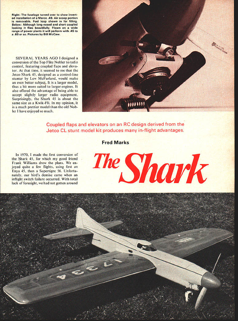
Coupled flaps and elevators on an RC design derived from the Jetco CL stunt model kit produces many in-flight advantages.
Fred Marks
SEVERAL YEARS AGO I designed a conversion of the Top Flite Nobler to radio control, featuring coupled flaps and elevator. At that time, it seemed to me that the Jetco Shark 45, designed as a control-line stunter by Lew McFarland, would make an even better subject. It is a larger model, thus a bit more suited to larger engines. It also offered the advantage of being able to accept slightly larger radio equipment. Surprisingly, the Shark 45 is about the same size as a Kwik-Fli. In my opinion, it is a much prettier model than the old Nobler I have enjoyed so much.
In 1970, I made the first conversion of the Shark 45, for which my good friend Frank Williams drew the plans. We enjoyed quite a few flights, using first an Enya 45, then a Supertigre 56. Unfortunately, our bird's demise came when an inflight switch failure occurred. With total lack of foresight, we had not gotten around to taking photos of the completed model.
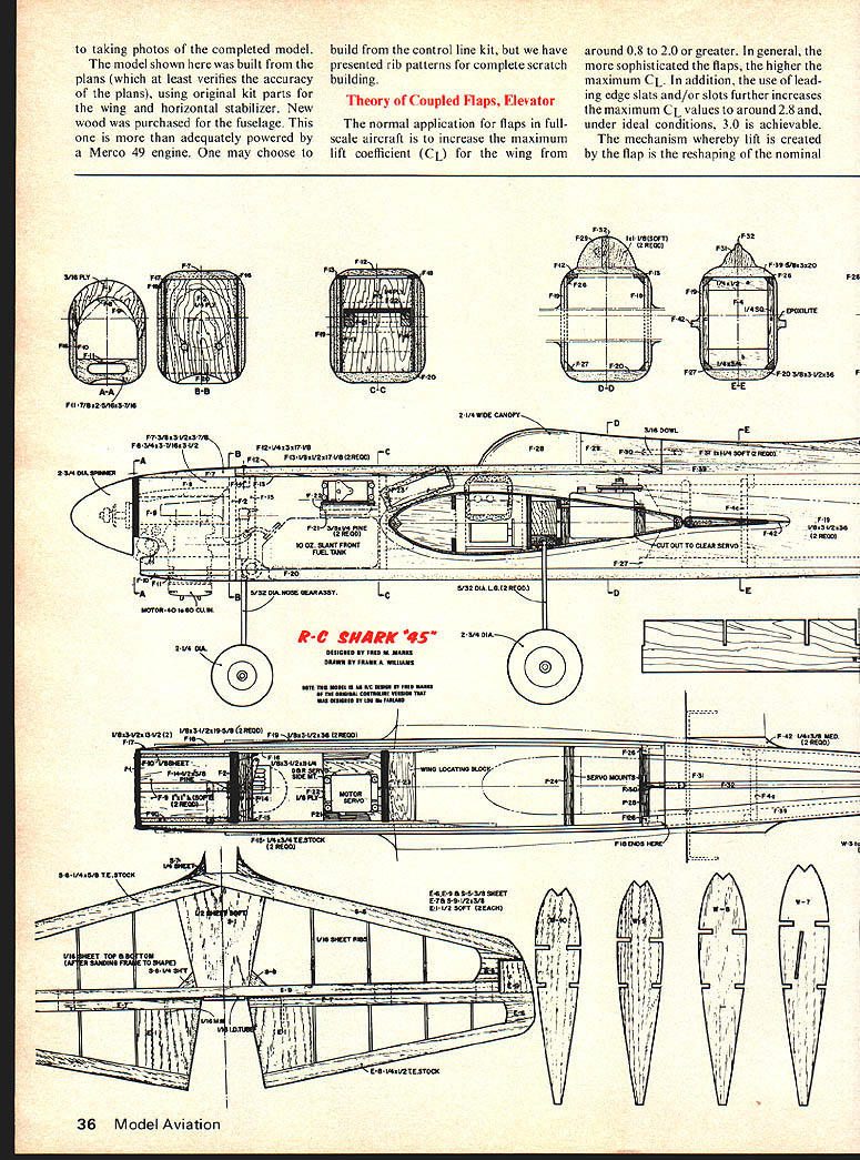
The model shown here was built from the plans (which at least verifies the accuracy of the plans), using original kit parts for the wing and horizontal stabilizer. New wood was purchased for the fuselage. This one is more than adequately powered by a Merco 49 engine. One may choose to build from the control-line kit, but we have presented rib patterns for complete scratch building.
Theory of Coupled Flaps, Elevator
The normal application for flaps in full-scale aircraft is to increase the maximum lift coefficient (CL) for the wing from around 0.8 to 2.0 or greater. In general, the more sophisticated the flaps, the higher the maximum CL. In addition, the use of leading-edge slats and/or slots further increases the maximum CL values to around 2.8 and, under ideal conditions, 3.0 is achievable.
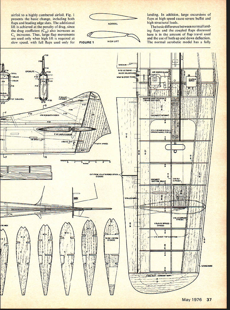
The mechanism whereby lift is created by the flap is the reshaping of the nominal wing camber. Figure 1 presents the basic change including both flaps and leading-edge slats. Additional lift is achieved at the penalty of increased drag since the drag coefficient (CD) also increases. Thus large flap movements are used for the high lift required at slow speed. Full flaps are used for normal landing. In addition, large excursions of flaps at high speed cause severe buffet and high structural loads.
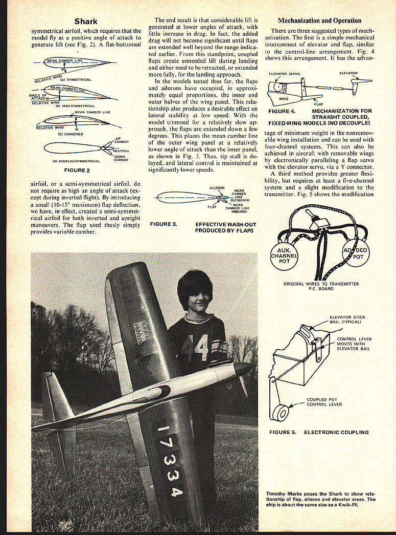
The basic difference between normal landing flaps and coupled flaps is the amount of flap travel used. Coupled flaps use both up and down deflection. A normal aerobatic model has a symmetrical airfoil and requires the model to fly at a positive angle of attack to generate lift (see Fig. 2). FLAT-BOTTOMED MEAN CAMBER LINE
SYMMETRICAL
ANGLE OF RELATIVE WIND
SEMI-SYMMETRICAL MEAN CAMBER LINE airfoil, or a semi-symmetrical airfoil, do not require as high an angle of attack (except during inverted flight). By introducing a small (10-15° maximum) flap deflection, we have, in effect, created a semi-symmetrical airfoil for both inverted and upright maneuvers. The flap used thusly simply provides variable camber.
The end result is that considerable lift is generated at lower angles of attack, with little increase in drag. In fact, the added drag will not become significant until flaps are extended well beyond the range indicated earlier. From this standpoint, coupled flaps create unneeded lift during landing and either need to be retracted, or extended more fully, for the landing approach.
In the models tested thus far, the flaps and ailerons have occupied, in approximately equal proportions, the inner and outer halves of the wing panel. This relationship also produces a desirable effect on lateral stability at low speed: With the model trimmed for a relatively slow approach, the flaps are extended down a few degrees. This places the mean camber line of the outer wing panel at a relatively lower angle of attack than the inner panel, as shown in Fig. 3. Thus, tip stall is delayed, and lateral control is maintained at significantly lower speeds.
Mechanization and Operation
There are three suggested types of mechanization. The first is a simple mechanical interconnect of elevator and flap, similar to the control-line arrangement. Fig. 4 shows this arrangement. It has the advantage of minimum weight in the nonremovable wing installation and can be used with four-channel systems. This can also be achieved in aircraft with removable wings by electronically paralleling a flap servo with the elevator servo, via a Y connector.
A third method provides greater flexibility, but requires at least a five-channel system and a slight modification to the transmitter. Fig. 5 shows the modification of the transmitter. This method requires an auxiliary channel pot and adds the pot to the transmitter P.C. board. The original wires to the transmitter P.C. board are re-routed and the added pot wired in to provide the coupled operation. The control lever moves with the elevator bail so that flap travel is proportional to elevator movement, yet allows independent trim of the flap through the auxiliary channel. The modifications made to the transmitters are simple, in that only the additions of a trim potentiometer, a switch, and linkage to actuate the added potentiometer are required.
Since transmitter layouts and arrangements vary so widely, there is little point in describing the detailed mechanization for these transmitters. Instead, the general arrangement shown in Fig. 5 should be followed. This consists of the following steps:
(1) Attach a linkage to the bail of the elevator stick so it can be used to move a control lever attached to the shaft of a good quality potentiometer. This pot is used for the coupled flap function. The ratio of elevator-pot-shaft rotation to rotation of the shaft of the added pot should be 4:1. This is achieved by making the radius of the link connection attached to the bail equal to one-fourth of the radius of the lever controlling the added pot.
(2) Connect the leads from the added pot (and the existing fifth-channel pot) to the end terminals of a DPDT switch (Fig. 5) and connect the common terminals of this switch to the printed circuit points to which the fifth-channel control pot wires originally connected.
With the above completed, one may select positionable flaps, controlled by the fifth-channel lever, or coupled flaps controlled by movement of the elevator stick in ratio of one-fourth of the movement of the elevator servo. The reason for this will become apparent a little later.
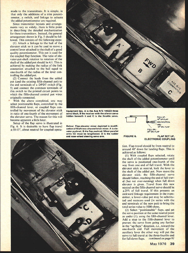
Setup of the flap servo is illustrated in Fig. 6. It is desirable to have flap travel ±10-15°, about neutral for coupled operation.
Flap travel should be from neutral to around 40° down for landing flaps. This is achieved as follows:
(1) With coupled flaps selected, rotate the shaft of the added potentiometer until the servo is positioned one-fourth of the way from one end of full travel. With the elevator stick at neutral, lock the lever to the shaft of the added pot. Now move the elevator stick; the fifth-channel servo should follow, reaching the end of full travel (but not over-running) when full down elevator is given. Travel from this new neutral on the fifth-channel servo should be ±25% of full travel. If this presents an awkward linkage requirement in the transmitter, a lower-value pot may be substituted and resistors used in series with the end terminals of the new pot to bring the total series value to 5000 ohms.
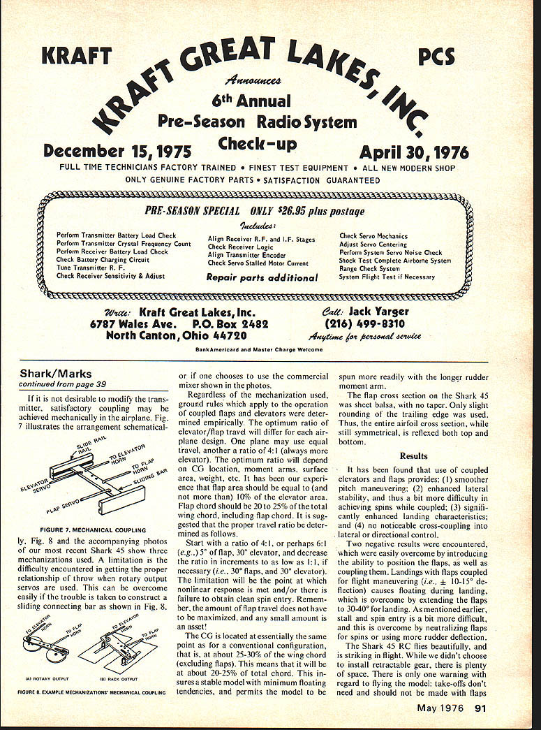
(2) Select "positionable" flaps, and set the servo position at the same neutral point as under (1) using the fifth-channel lever. Add a stop to the fifth-channel lever to prevent the servo from going any further in the "up flaps" direction, i.e., toward the one-fourth end. Full movement of the auxiliary lever the other way will put the servo to full travel at the three-fourths end for full down flaps. If it is not desirable to modify the transmitter, satisfactory coupling may be achieved mechanically in the airplane. Fig. 7 illustrates the arrangement schematically. Fig. 8 and the accompanying photos of our most recent Shark 45 show three mechanizations used. A limitation is the difficulty encountered in getting the proper relationship of throw when rotary output servos are used. This can be overcome easily if the trouble is taken to construct a sliding connecting bar as shown in Fig. 8, or if one chooses to use the commercial mixer shown in the photos.
Regardless of the mechanization used, ground rules which apply to the operation of coupled flaps and elevators were determined empirically. The optimum ratio of elevator/flap travel will differ for each airplane design. One plane may use equal travel, another a ratio of 4:1 (always more elevator). The optimum ratio will depend on CG location, moment arms, surface area, weight, etc. It has been our experience that flap area should be equal to (and not more than) 10% of the elevator area. Flap chord should be 20 to 25% of the total wing chord, including nap chord. It is suggested that the proper travel ratio be determined as follows.
Start with a ratio of 4:1, or perhaps 6:1 (e.g., 3° of flap, 30° elevator), and decrease the ratio in increments as low as 1:1, if necessary (i.e., 30° flaps, and 30° elevator). The limiting factor will be the point at which nonlinear response is met and/or there is failure to obtain clean spin entry. Remember, the amount of flap travel does not have to be maximized, and any small amount is an asset.
The CG is located at essentially the same point as for a conventional configuration, that is, at about 25-30% of the wing chord (excluding flaps). This means that it will be at about 20-25% of total chord. This ensures a stable model with minimum floating tendencies, and permits the model to be spun more readily with the longer rudder moment arm.
The flap cross section on the Shark 45 was balsa, with no taper. Only slight rounding of the trailing edge was used. Thus, the entire airfoil cross section, while still symmetrical, is reflexed both top and bottom.
Results
It has been found that use of coupled elevators and flaps provides: (1) smoother pitch maneuvering; (2) enhanced lateral stability, and thus a bit more difficulty in achieving spins while coupled; (3) significantly enhanced landing characteristics; and (4) no noticeable cross-coupling into lateral or directional control.
Two negative results were encountered, which were easily overcome by introducing the ability to position the flaps, as well as coupling them. Landings with flaps coupled exhibited high float characteristics (i.e., 10-15° of flaps) causing stalling during landing, which is overcome by extending the flaps to 30-40° for landing. As mentioned earlier, stall and spin entry is a bit more difficult, and this is overcome by neutralizing flaps for spins or using more rudder deflection.
The Shark 45 RC flies beautifully and is striking in flight. While we didn't choose to install retractable gear, there is plenty of space. There is only one warning with regard to flying the model: take-offs don't need and should not be made with flaps down.
Shark (continued)
extended to the landing position. Our only attempt resulted in liftoff after just 10 ft. of roll, but with a requirement for full right rudder to prevent an auger-in. Landings are soft and easy, with no tendency to float with the flaps moved to a landing position (at least 25°, but no more than 30°). Attempts to land with the flaps coupled, i.e., travel of ±15°, result in floating. With the flaps set at 25° in calm air, I have demonstrated stable approach and smooth touchdown from 200 ft. out with my hands completely off the transmitter!
If you like things different and exciting, you will enjoy the Shark 45 RC.
Construction
Because this is not exactly a beginner's model, we won't present step-by-step instructions. All wood parts are identified or coded on the plan so that, if you "reconstruct" a kit from raw materials you can mark the parts with a felt-tip pen for easy finding when you build. The wing is built exactly per the plans. However, don't use the control line plans, since one wing panel is a rib bay longer than the other. Not only will it look funny, but you'll also get bad roll trim! While the plans show the forward fuselage doublers laminated from several layers of 1/8" balsa, one may choose to use a single, thicker piece (say 3/8"), then taper as shown at the aft end. Complete the fuselage, attach the horizontal stabilizer, that beautifully long canopy fairing, dorsal fin, and the vertical stabilizer. For securing the hatch, use a 4-40 bolt tapped into a maple block at the front, combined with a dowel peg at the aft end.
Our model's fuselage was covered with silk and dope. One problem was encountered: The silk pulled away at the glue joint that runs the length of the dorsal fin. This is best overcome by slitting the silk and doping it down tightly at the junction. Where the gap results between the silk and edges at the juncture, use resin and microballoons to form a small fillet.
We recommend that the fuselage be covered before the wing is installed and wing fillets added. With the wing aligned and epoxied in place, use epoxy or resin and micro-balloons to form a fillet. Cover the wing and horizontal stabilizer with MonoKote or other heat-shrinking covering. Be sure to cut and form a straight-edge at the root end. Mask this straight-edge, as well as the covering, then proceed to fill and finish the fuselage with your favorite finishing materials.
Acknowledgments: To Frank Williams, for drawing the plans; Bill McCaw, for the photos; Hobie Steele and Jack Dorman, for aid in construction. I hasten to add that all of the original was built by the author, but the model crashed as mentioned earlier. We also acknowledge the original beautiful Shark 45 design by Lou McFarland.
Transcribed from original scans by AI. Minor OCR errors may remain.

