
THE SHELL GAME
Full-scale stressed-skin aircraft have been built of plywood, sheet metal and, recently, fiberglass. Sheet or shell structures are very efficient and are used for this reason as well as for obtaining smooth aerodynamic surfaces. Shells are not always the lightest structures, since even the thinnest usable material may produce a structure much stronger than is needed. On this account, framed structures may be best for small aircraft.
Shells function as hollow beams and depend on their shape for strength and stiffness. Failure results because of local crumpling or rupture. If you bend a soda straw or other paper tube it will fail by collapsing at one or more places. In wings and fuselages, ribs, rings and stiffeners prevent or delay such collapse.
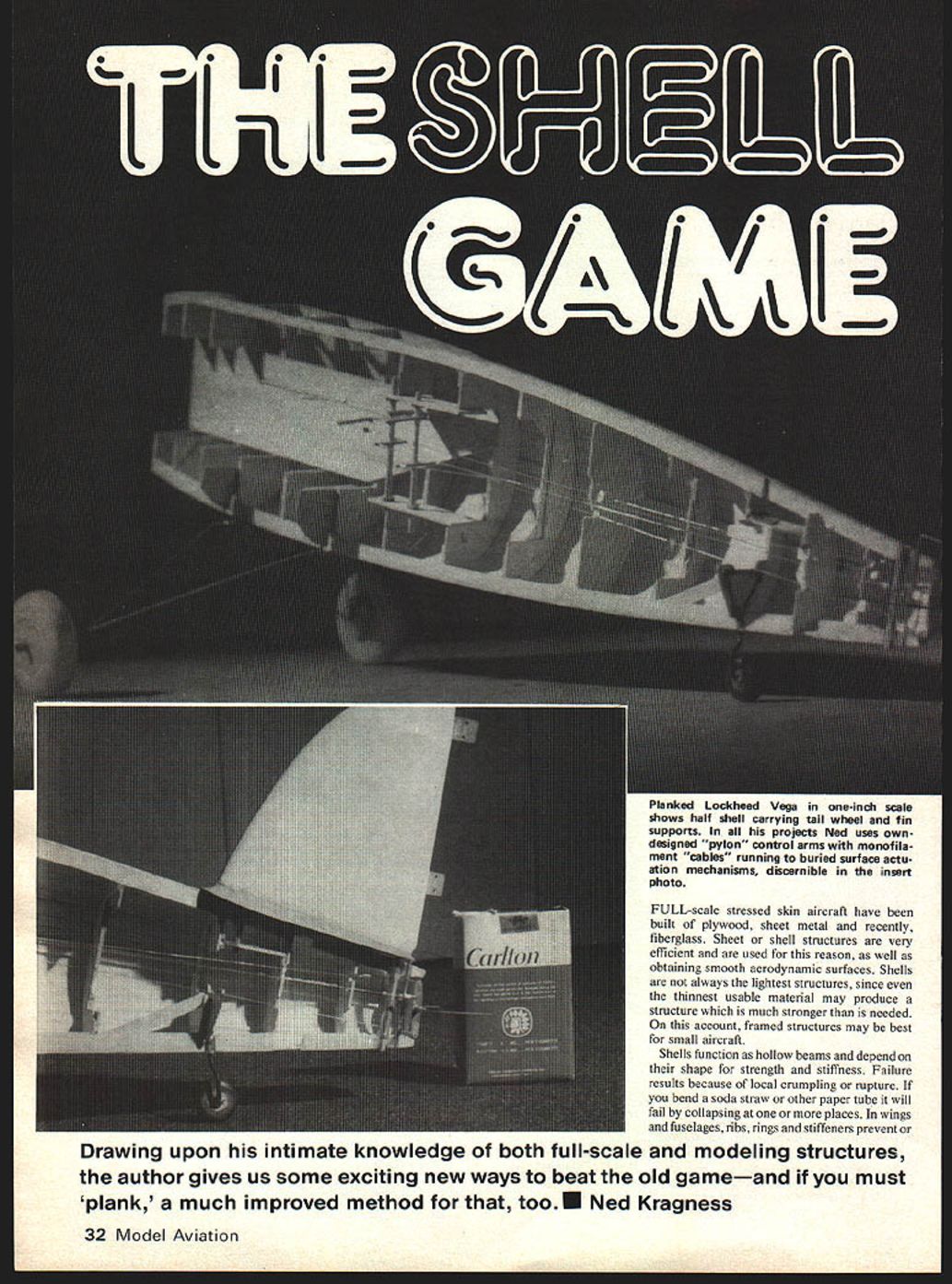
Drawing upon his intimate knowledge of both full-scale and modeling structures, the author gives us some exciting new ways to beat the old game — and if you must "plank," a much improved method for that, too. — Ned Kragness
Doublers are used to increase thickness for local high loads.
For structural efficiency and scale appearance, shells would be desirable model structures. They have not been much used, however, because construction difficulties seem too great. Occasional carved and hollowed blocks were once seen, but balsa blocks become expensive in large sizes. For small components one can still use this technique, particularly where curvature is abrupt, such as engine cowls, tailcones and transition pieces.
There are two broad geometric classes for such shells. Both classes are usually found somewhere in each aircraft, depending on structural needs and aerodynamic considerations. The first class of curvature in character is "developable," which means that if it is cut along a straight line or along a simple curve, the resulting shape can be unrolled into a flat sheet. This is the most common: the Luscombe fuselage had only one non-developable sheet. The second class, non-developable or compound curvature, is best exemplified by the egg or a ball. Here there is no cut that can be made which will permit us to flatten its skin or surface without a non-uniform shrinking, stretching or tearing of the skin material. Most aircraft compound forms are approximated by a number of non-compound curves. As the most familiar example, consider the common world globe, most of which are made up of a number of printed flat "gores." Full-size aircraft usually exploit this trick. We will return to this later.
Shell Fuselage Construction
Metal or plywood-skinned fuselage or hull structures are more difficult to model if compound curvatures must be built. The least attractive method used on very light models involves stringers and bulkheads covered with tissue, silk, or plastic film. Each stringer remains clearly visible, as will at least some of the bulkhead edges. Another method, heavier but of better appearance, involves planking over bulkheads and sanding the rough exterior to a smooth contour and finish. More sophisticated approaches by molding plastics can yield more realistic but heavier structures; however, molding plastics involves making molds.
A different technique for producing shells has been worked out. It depends on the flexibility of balsa in bending parallel to its grain. It also depends on the fact that full-scale aircraft appear to display compound curvatures but are actually composed of simple curves assembled together without compound curves in any individual sheet. We can do the same thing.
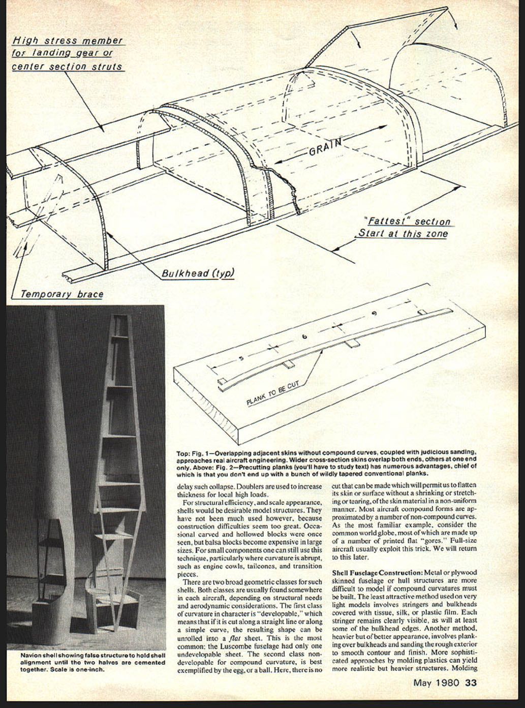
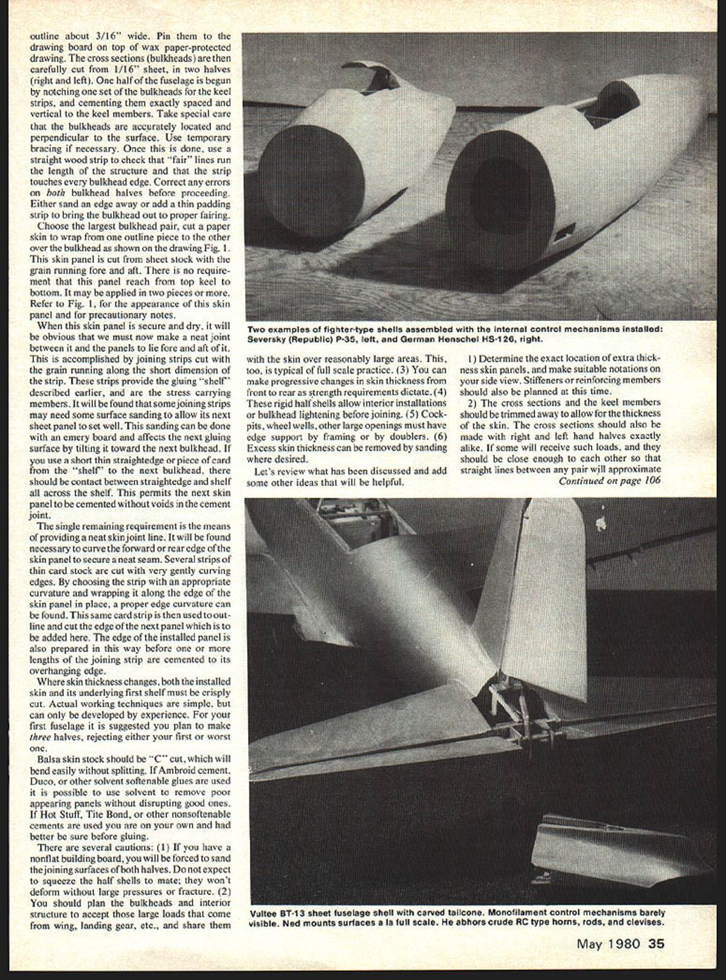
If we examine drawings and photographs we can frequently discern the full-scale aircraft segmentation into simply-curved wrapped sheets reaching from one bulkhead or former to the next, either forward or aft. If we take the Henschel HS-126 fuselage shown, it is immediately apparent that the cockpit-zone side sheets could be easily installed without buckling.
However, this leaves the problem of how to manage the apparent compound curvatures forward and aft. If we remember that a series of connecting short straight lines can look like a curve, particularly for short-line pieces at small angles, we can divide the shell into segments which join at small angles.
We start with the fattest pair of bulkheads, and place a skin panel to extend past both bulkheads by at least 3/16". Under this overhang we then cement a 3/32" wide strip. This strip will now provide a joining surface for the next skin panels fore and aft, each of which will in turn extend past its next bulkhead, so that the process can be repeated.
The procedure is thus carried both fore and aft, with the alternation permitting work on one panel while the preceding one dries in place. The progressing structure should appear as shown in the drawing (Fig. 1).
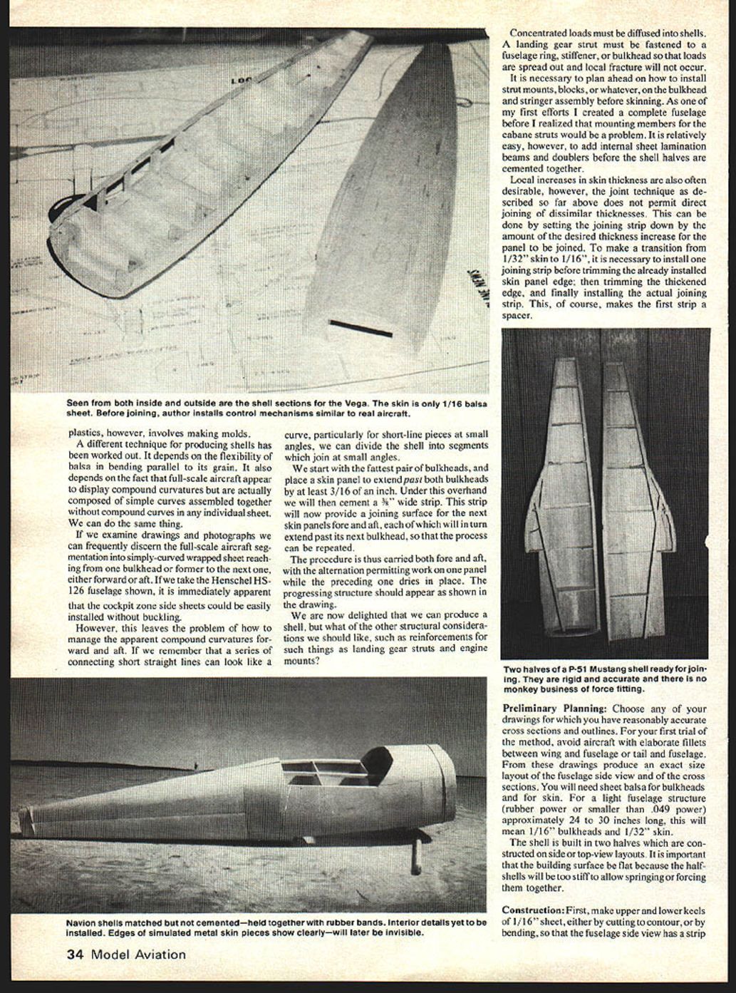
We are now able to produce a shell, but what of other structural considerations such as reinforcements for landing gear struts and engine mounts?
Concentrated loads must be diffused into shells. A landing gear strut must be fastened to a fuselage ring, stiffener, or bulkhead so that loads are spread out and local fracture will not occur.
It is necessary to plan ahead how to install strut mounts, blocks, or whatever on the bulkhead and stringer assembly before skinning. As one of my first efforts I created a complete fuselage before I realized that mounting members for the cabane struts would be a problem. It is relatively easy, however, to add internal sheet-lamination beams and doublers before the shell halves are cemented together.
Local increases in skin thickness are also often desirable; however, the joint technique as described so far does not permit direct joining of dissimilar thicknesses. This can be done by setting the joining strip down by the amount of the desired thickness increase for the panel to be joined. To make a transition from 1/32" skin to 1/16", it is necessary to install one joining strip before trimming the already installed skin-panel edge; then trim the thickened edge, and finally install the actual joining strip. This, of course, makes the first strip a spacer.
Preliminary Planning
Choose any of your drawings for which you have reasonably accurate cross sections and outlines. For your first trial of the method, avoid aircraft with elaborate fillets between wing and fuselage or tail and fuselage. From these drawings produce an exact-size layout of the fuselage side view and of the cross sections. You will need sheet balsa for bulkheads and for skin. For a light fuselage structure (rubber-power or smaller than .049 power) approximately 24" to 30" long, this will mean 1/16" bulkheads and 1/32" skin.
The shell is built in two halves which are constructed on side- or top-view layouts. It is important that the building surface be flat because the half-shells will be too stiff to allow springing or forcing them together.
Construction
First, make upper and lower keels of 1/16" sheet, either by cutting to contour or by bending, so that the fuselage side view has a strip outline about 3/16" wide. Pin them to the drawing board on top of wax-paper-protected drawing. The cross sections (bulkheads) are then carefully cut from 1/16" sheet, in two halves (right and left). One half of the fuselage is begun by notching one set of the bulkheads for the keel strips, and cementing them exactly spaced and vertical to the keel members. Take special care that the bulkheads are accurately located and perpendicular to the surface. Use temporary bracing if necessary.
Once this is done, use a straight wood strip to check that "fair" lines run the length of the structure and that the strip touches every bulkhead edge. Correct any errors on both bulkhead halves before proceeding. Either sand an edge away or add a thin padding strip to bring the bulkhead out to proper fairing.
Choose the largest bulkhead pair, cut a paper skin to wrap from one outline piece to the other over the bulkhead as shown on the drawing (Fig. 1). This skin panel is cut from sheet stock with the grain running fore and aft. There is no requirement that this panel reach from top keel to bottom; it may be applied in two pieces or more. Refer to Fig. 1 for the appearance of this skin panel and for precautionary notes.
When this skin panel is secure and dry, it will be obvious that we must now make a neat joint between it and the panels to lie fore and aft of it. This is accomplished by joining strips cut with the grain running along the short dimension of the strip. These strips provide the gluing "shelf" described earlier and are the stress-carrying members. It will be found that some joining strips may need some surface sanding to allow the next sheet panel to set well. This sanding can be done with an emery board and affects the next gluing surface by tilting it toward the next bulkhead. If you use a short thin straightedge or piece of card from the "shelf" to the next bulkhead, there should be contact between straightedge and shelf all across the shelf. This permits the next skin panel to be cemented without voids in the cement joint.
The single remaining requirement is the means of providing a neat skin-joint line. It will be found necessary to curve the forward or rear edge of the skin panel to secure a neat seam. Several strips of thin card stock are cut with very gently curving edges. By choosing the strip with an appropriate curvature and wrapping it along the edge of the skin panel in place, a proper edge curvature can be found. This same card strip is then used to outline and cut the edge of the next panel which is to be added here. The edge of the installed panel is also prepared in this way before one or more lengths of the joining strip are cemented to its overhanging edge.
Where skin thickness changes, both the installed skin and its underlying first shelf must be crisply cut. Actual working techniques are simple, but can only be developed by experience. For your first fuselage it is suggested you plan to make three halves, rejecting either your first or worst one.
Balsa skin stock should be "C" cut, which will bend easily without splitting. If Ambroid cement, Duco, or other solvent-softenable glues are used it is possible to use solvent to remove poor-appearing panels without disrupting good ones. If Hot Stuff, Tite Bond, or other non-softenable cements are used you are on your own and had better be sure before gluing.
There are several cautions:
- If you have a non-flat building board, you will be forced to sand the joining surfaces of both halves. Do not expect to squeeze the half-shells to mate; they won't deform without large pressures or fracture.
- Plan the bulkheads and interior structure to accept those large loads that come from wing, landing gear, etc., and share them with the skin over reasonably large areas. This is typical of full-scale practice.
- You can make progressive changes in skin thickness from front to rear as strength requirements dictate.
- These rigid half-shells allow interior installations or bulkhead lightening before joining.
- Cockpits, wheel wells and other large openings must have edge support by framing or by doublers.
- Excess skin thickness can be removed by sanding where desired.
Let's review what has been discussed and add some other ideas that will be helpful.
- Determine the exact location of extra-thickness skin panels, and make suitable notations on your side view. Stiffeners or reinforcing members should also be planned at this time.
- The cross sections and the keel members should be trimmed away to allow for the thickness of the skin. The cross sections should also be made with right- and left-hand halves exactly alike. If some will receive heavy loads, they should be close enough to each other so that straight lines between any pair will approximate a curve.
- The side-view drawing must be sharply drawn and this drawing must be on translucent paper, or accurately duplicated, right and left hand. Be sure you make the fuselage in one right and one left half shell.
- Use as many bulkheads as you feel are desirable without much regard for weight. A considerable amount of weight can be deleted when the bulkheads are cut away to narrow half rings just prior to final joining of the two half-shells. For non-major bulkheads this cut-away may even extend to the skin-joining strips.
- You will find that considerable accuracy is desirable in the exact location of the bulkheads on the keel strips, their squareness with the drawing or work board, and in holding the keel strips solidly to the work-board surface.
- The best gluing clamp for final joining is a strip of 1/4" flat rubber wound spirally around the two halves with only the lightest tension which will bring them into good contact. It is a good idea to make completely closed shells and make cutouts for cockpits, etc., later.
- Some practice and experimenting will allow you to master this technique. The various 3/4" scale HS-126 shell shown weighs 1.7 ounces and is 18" long; it is primarily 1/32" skin over 1/16" bulkheads with one 1/4" x 1/16" side-stringer strip.
Planked Shells
There are shapes that yield best to planking. Most of what was said about concentrated loads also applies to planked shells. As an example, consider the Lockheed Vega (Orion, Sirius, Altair, etc.). The photos show a 1/12-scale model constructed with 1/16" planking.
The fuselage geometry is totally symmetrical. If divided or cut along the horizontal center plane, both top and bottom are identical. If cut on the vertical plane, right and left half-shells are identical.
The Lockheed Vega fuselage was a wood molding using two identical shells laminated with glue and pressed in a concrete mold. The shell skin was of varying thickness, thicker at the front where landing gear, wing and engine imposed large loads. The assembled shells were reinforced with internal rings and longitudinals all joined together to produce a light, strong and efficient fuselage.
A good fuselage shell could be molded in the same way but would require far too much work in making the mold and then reinforcing the shells. Planking is our most reasonable choice. We will do it a bit differently, however, relying less on thick balsa than on technique.
We will start by repeating some of the shell-technique steps already described.
The first step is to produce a side view and accurate cross sections for each stress location such as wing-spar, firewall, and landing-gear attachment stations. Other intermediate cross sections will be needed to produce a good form and perhaps reinforce the hand-launching grip zone.
Set up top and bottom outline strips on the drawing and create half bulkheads, just as was done for the sheet-shell assembly. Again, be accurate so that the bulkhead edges will meet and join when the shells are mated together.
Since both halves should be identical, use fairing strips to find where contour changes or corrections are needed on the half bulkheads on the first half shell, and then correct the other halves to match. Now lay a single 1/4" x 1/16" stringer from front to rear along the horizontal center-belt line. It should be notched flush with the bulkheads.
One problem in planking a fuselage or boat hull is that the planks must be narrower as they get to smaller sections. The boat builder has a technique he calls "spiling" — used to establish the taper necessary. Spiling would be very difficult and tedious for model work, so we tackle the problem another way.
We need to make long, gently curved taper planks to allow for the change in fuselage circumference, and we will cut these curves with a straightedge.
Four 1/16" high jigging blocks will be cemented to your cutting board. When a 5/16" x 1/16" strip is forced into the curve by these blocks, a straight-line cut will become a curve when the strip is allowed to unbend. If the straight cut is made with the blade several degrees off vertical, there will be a bevel edge on the curved edge, which can assist in getting a good edge joint. Fig. 1 shows a layout of jigging blocks which were used for this 1/12-scale Lockheed Vega.
If the largest semi-circumference of the fuselage is, for example, 5", and we expect to use 1/4"-wide planks, there will be 20 planks required. However, if the small end has a semi-circumference of 1 1/4", then the planks must taper to 1/16" wide at that end.
This arithmetic is useful but accuracy in this size is not up to producing perfect matching. You will still have to make an adjustment on the last one or two planks.
Proceed from the center line of the belt-line stringer, making sure there is no cement squeeze-out to interfere with the next plank. Add a plank on each side of the belt line, alternating above it and below, watching progress in covering the shell fore and aft. It will probably be necessary to change the block spacing of the cutting jig to adjust the plank taper. If the final plank does not perfectly fill the remaining gap at the top and bottom stringer, don't worry. With more than three-quarters of the shell in place, the shell can be lifted off the board and a tailored plank can be placed.
Transcribed from original scans by AI. Minor OCR errors may remain.

