
Short Seamew
Much overlooked British Naval aircraft offers unique features and distinctive performance for the Class I Navy Carrier event as powered by the Supertigre G40 engine.
Richard L. Perry
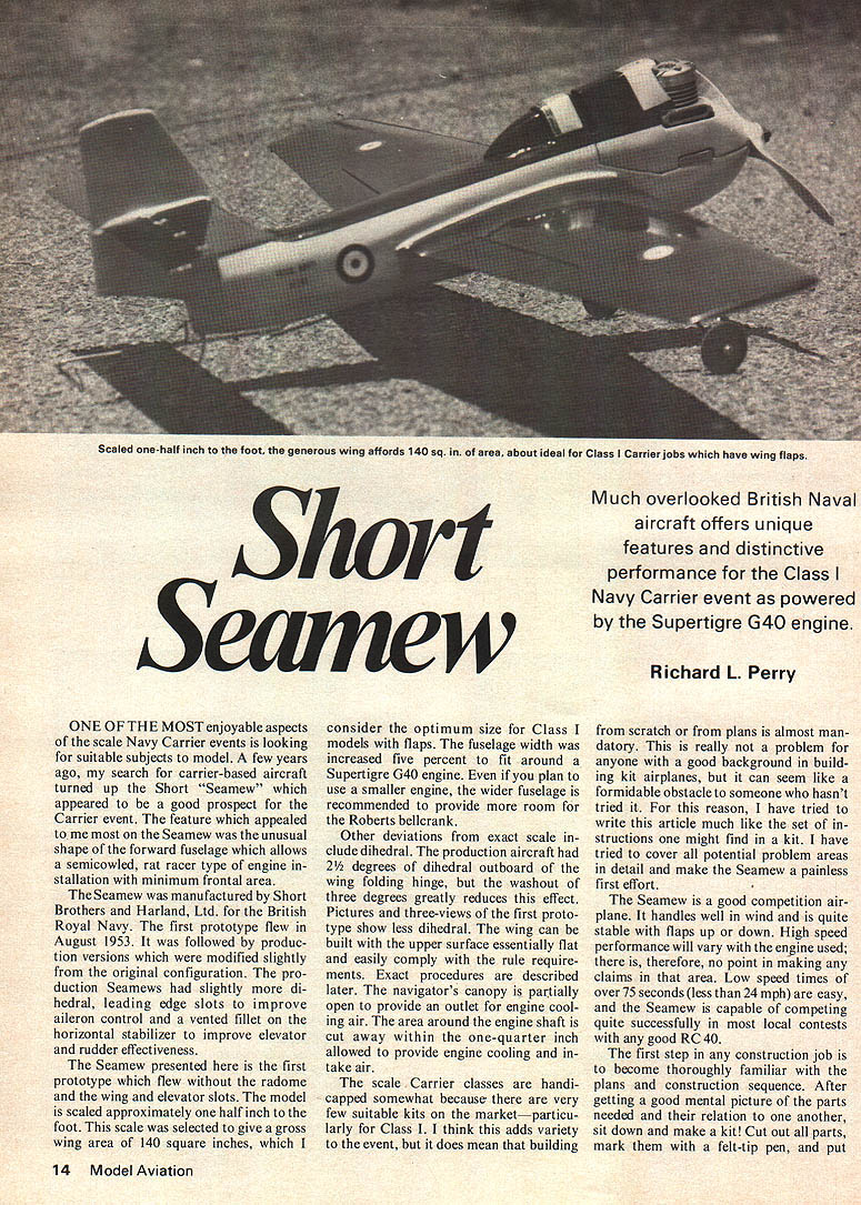
ONE OF THE MOST enjoyable aspects of the scale Navy Carrier events is looking for suitable subjects to model. A few years ago, my search for carrier-based aircraft turned up the Short "Seamew" which appeared to be a good prospect for the Carrier event. The feature which appealed to me most on the Seamew was the unusual shape of the forward fuselage which allows a semicowled, rat racer type of engine installation with minimum frontal area.
The Seamew was manufactured by Short Brothers and Harland, Ltd. for the British Royal Navy. The first prototype flew in August 1953. It was followed by production versions which were modified slightly from the original configuration. The production Seamews had slightly more dihedral, leading edge slots to improve aileron control and a vented fillet on the horizontal stabilizer to improve elevator and rudder effectiveness.
The Seamew presented here is the first prototype which flew without the radome and the wing and elevator slots. The model is scaled approximately one-half inch to the foot. This scale was selected to give a gross wing area of 140 square inches, which I consider the optimum size for Class I models with flaps. The fuselage width was increased five percent to fit around a Supertigre G40 engine. Even if you plan to use a smaller engine, the wider fuselage is recommended to provide more room for the Roberts bellcrank.
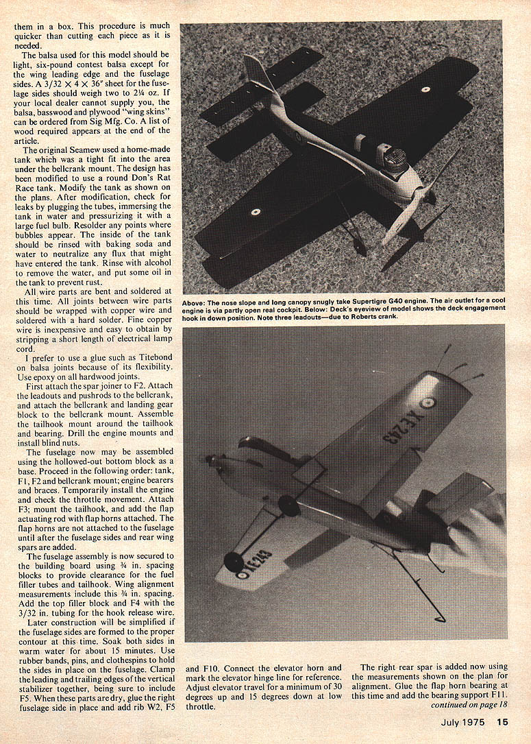
Other deviations from exact scale include dihedral. The production aircraft had 2½ degrees of dihedral outboard of the wing folding hinge, but the washout of three degrees greatly reduces this effect. Pictures and three-views of the first prototype show less dihedral. The wing can be built with the upper surface essentially flat and easily comply with the rule requirements. Exact procedures are described later. The navigator's canopy is partially open to provide an outlet for engine cooling air. The area around the engine shaft is cut away within the one-quarter inch allowed to provide engine cooling and intake air.
The scale Carrier classes are handicapped somewhat because there are very few suitable kits on the market—particularly for Class I. I think this adds variety to the event, but it does mean that building from scratch or from plans is almost mandatory. This is really not a problem for anyone with a good background in building kit airplanes, but it can seem like a formidable obstacle to someone who hasn't tried it. For this reason, I have tried to write this article much like the set of instructions one might find in a kit. I have tried to cover all potential problem areas in detail and make the Seamew a painless first effort.
The Seamew is a good competition airplane. It handles well in wind and is quite stable with flaps up or down. High speed performance will vary with the engine used; therefore, no point in making any claims in that area. Low speed times of over 75 seconds (less than 24 mph) are easy, and the Seamew is capable of competing quite successfully in most local contests with any good RC .40.
The first step in any construction job is to become thoroughly familiar with the plans and construction sequence. After getting a good mental picture of the parts needed and their relation to one another, sit down and make a kit! Cut out all parts, mark them with a felt-tip pen, and put them in a box. This procedure is much quicker than cutting each piece as it is needed.
The balsa used for this model should be light, six-pound contest balsa except for the wing leading edges and the fuselage sides. A 3/32 x 4 x 36" sheet for the fuselage sides should weigh two to 2 1/4 oz. If your local dealer cannot supply you, the balsa, basswood and plywood "wing skins" can be ordered from Sig Mfg. Co. A list of wood required appears at the end of the article.
The original Seamew used a home-made tank which was a tight fit into the area under the bellcrank mount. The design has been modified to use a round Don's Rat Race tank. Modify the tank as shown on the plans. After modification, check for leaks by plugging the tubes, immersing the tank in water and pressurizing it with a large fuel bulb. Resolder any points where bubbles appear. The inside of the tank should be rinsed with baking soda and water to neutralize any flux that might have entered the tank. Rinse with alcohol to remove the water, and put some oil in the tank to prevent rust.
All wire parts are bent and soldered at this time. All joints between wire parts should be wrapped with copper wire and soldered with a hard solder. Fine copper wire is inexpensive and easy to obtain by stripping a short length of electrical lamp cord.
I prefer to use a glue such as Titebond on balsa joints because of its flexibility. Use epoxy on all hardwood joints.
First attach the spar joiner to F2. Attach the leadouts and pushrods to the bellcrank, and attach the bellcrank and landing gear block to the bellcrank mount. Assemble the tailhook mount around the tailhook bearing. Drill the engine mounts and install blind nuts.
The fuselage now may be assembled using the hollowed-out bottom block as a base. Proceed in the following order: tank, F1, F2 and bellcrank mount; engine bearers and braces. Temporarily install the engine and check the throttle movement. Attach F3; mount the tailhook, and add the flap actuating rod with flap horns attached. The flap horns are not attached to the fuselage until after the fuselage sides and rear wing spars are added.
The fuselage assembly is now secured to the building board using 3/4 in. spacing blocks to provide clearance for the filler tubes and tailhook. Wing alignment measurements include this 3/4 in. spacing. Add the top filler block and F4 with the 3/32 in. tubing for the hook release wire.
Later construction will be simplified if the fuselage sides are formed to the proper contour at this time. Soak both sides in warm water for about 15 minutes. Use rubber bands, pins, and clothespins to hold the sides in place on the fuselage. Clamp the leading and trailing edges of the vertical stabilizer together, being sure to include F5. When these parts are dry, glue the right fuselage side in place and add rib W2, F5 and F10. Connect the elevator horn and mark the elevator hinge line for reference. Adjust elevator travel for a minimum of 30 degrees up and 15 degrees down at low throttle.
The right rear spar is added now using the measurements shown on the plan for alignment. Glue the flap horn bearing at this time and add the bearing support F11.
Short Seamew
Fit the fuselage top in place temporarily, and glue in F10 through F9 using waxed paper to avoid gluing the fuselage top on permanently. Remove the fuselage top, and attach the left fuselage side and spar in the same manner as the right. Secure the flap horn and remove the assembly from the board to check flap travel (40 to 45 degrees) and the entire control system. Return the model to the building board, and install the fuselage top.
Add the 1/2 in. balsa leading edges, which must be flat on the bottom edge, and ribs W7. Adjust the LE to the measurements shown on the plan. Add ribs W3 through W6 and the trailing edge pieces, being sure to align the bottom of the ribs with the bottom of the LE. Install the flap blanks on their hinges (be sure the tailhook is latched up). The wing leading edges and trailing edges are carved to shape at this time. A pin through the rear spar into the flap will help secure it for this operation. Remove the pin before covering the wing.
The 1/64 in. plywood wing covering is next. Use epoxy (sparingly, it doesn't evaporate). Titebond or its equivalent will work, but it makes the plywood expand slightly and can cause some troubles. Fit the pieces carefully. It is best to cover the flaps separately; use caution to avoid getting glue in the flap hinges. Attach the top surface first and, while it is curing, put on the stabilizer, checking that it is level with the cowl. Invert the model, block the tips to prevent warps, and apply the bottom sheeting. Don't forget the tip weight. Now add the tips.
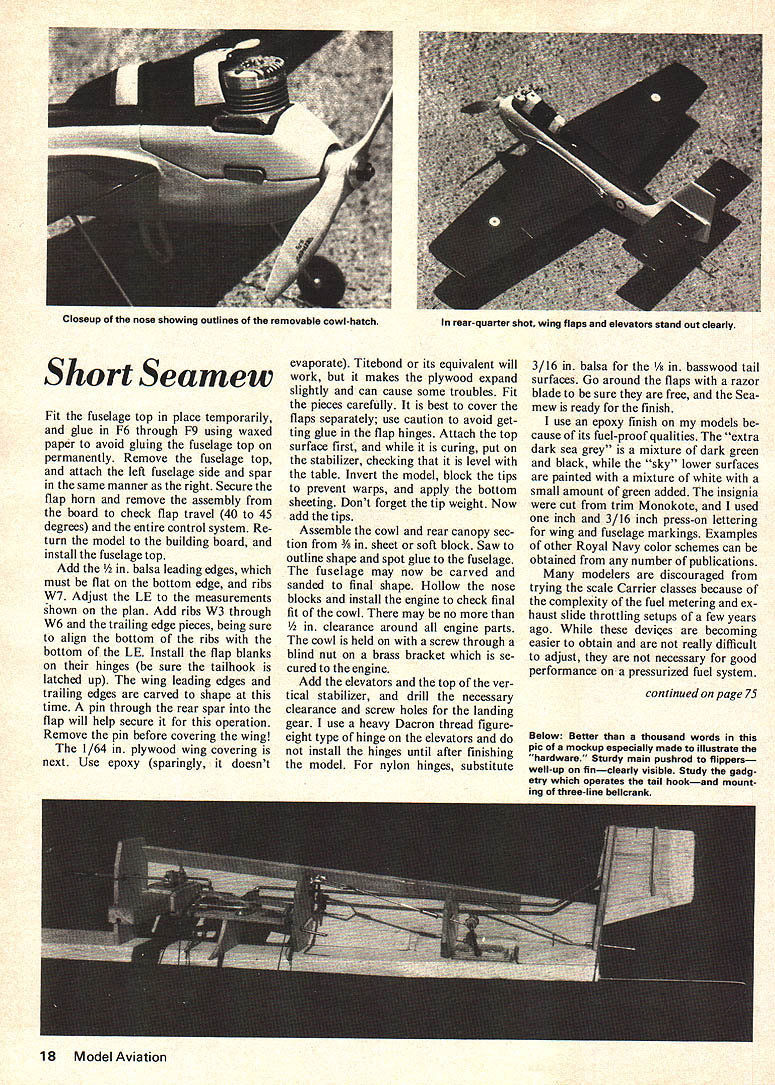
Assemble the cowl and rear canopy section from 3/16 in. sheet or soft block. Saw to outline shape and spot glue to the fuselage. The fuselage may now be carved and sanded to final shape. Hollow the nose blocks and install the engine to check final fit of the cowl. There may be no more than 1/8 in. clearance around all engine parts. The cowl is held on with a screw through a blind nut on a brass bracket which is secured to the engine.
Add the elevators and the top of the vertical stabilizer, and drill the necessary clearance and screw holes for the landing gear. I use a heavy Dacron thread for the type of hinge on the elevators and do not install the hinges until after finishing the model. For nylon hinges, substitute 3/16 in. balsa for the 1/8 in. basswood tail surfaces. Go around the flaps with a razor blade to be sure they are free, and the Seamew is ready for the finish.
I use an epoxy finish on my models because of its fuel-proof qualities. The "extra dark sea grey" is a mixture of dark green and black, while the "sky" lower surfaces are painted with a mixture of white with a small amount of green added. The insignia are cut from trim Monokote, and I used 1/16 in. and 3/16 in. press-on lettering for wing and fuselage markings. Examples of other Royal Navy color schemes can be obtained from any number of publications.
Many modelers are discouraged from trying the scale Carrier classes because of the complexity of the fuel metering and exhaust slide throttling setups of a few years ago. While these devices are becoming easier to obtain and are not really difficult to adjust, they are not necessary for good performance on a pressurized fuel system.
Short Seamew
I run Supertigre G40 engines with a stock Supertigre pressure carburetor using the timed pressure tap. The only addition I make is to add a check valve to the pressure line (available from George Aldrich) to obtain more even pressure at idle. There are quite a few throttles available that have the necessary fuel metering built in to handle pressure.
There are numerous commercial fuels on the market which are highly competitive. I have used K&B Speed Fuel and RO-GO 58 percent fuel with good results. Any increase in performance with home-brew is so small that it is not worth the trouble to make it.
The correct propeller will vary from one engine-plane combination to the next. I use a Rev-Up 9-1/2 cut down to 8-1/2 inch diameter with good results. Other popular sizes for Class I are 8-8 and 9-7. In general, lower pitch props with more blade area will be better for heavier models while the lighter ones can use higher pitch props without hurting acceleration. Experimentation is the only good way to determine which prop is best for a particular model.
With careful building and plenty of sandpaper during the finishing, the Seamew can weigh 28 to 30 oz. depending on the engine.
Practice is important for competing successfully in Carrier. Get to know your engine and the capabilities of your airplane. The advantages of practicing slow flight and landings are obvious, but the high speed portion of the flight is not to be ignored—particularly the take-off. High speed is weighted quite heavily in Carrier, and the name of the game is acceleration. Climbing above a six-foot altitude hurts acceleration; at half a lap, a plane at 20 feet will be at least five mph slower than the same plane at five feet. The deck is plenty long enough to get airborne without using up elevator, and zooming off the deck will only hurt acceleration by adding drag and gaining excessive altitude.
I will be happy to hear from you at 5016 Angelita Ave., Dayton, Ohio 45424, concerning the Seamew or any other Carrier subject. I hope I have tempted you to try Class I Carrier. Good luck, and may all your landings be 100 points.
References: Jane's All the World's Aircraft; L. Bridgen, editor; McGraw-Hill Book Company, Inc., New York, (1954-1955, 1955-1956, 1956-1957). All the World's Fighting Planes; W. Green and G. Pollinger, MacDonald and Co., Ltd., London, 1956.
WOOD REQUIRED qty. size 1 12 x 48 x 1/64" plywood wing skins 1 3/32 x 4 x 36" medium light balsa 2 3/8 x 3 x 36" light balsa 1 1/8 x 3 x 24" basswood 1 1/2 x 1/2 x 1/32" medium-hard balsa
Small quantities of: 3/8" basswood, 3/16" balsa, 3/32" plywood, 3/8 x 1/2" maple.
Transcribed from original scans by AI. Minor OCR errors may remain.

