
Short Sterling
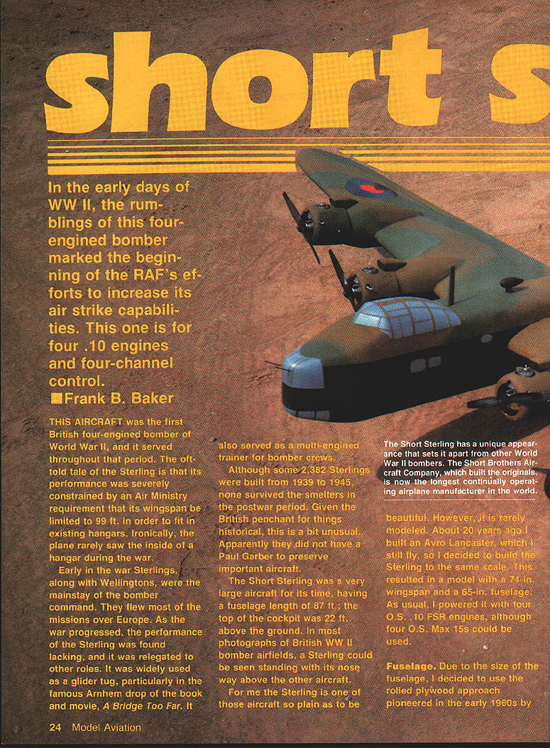
In the early days of World War II, the rumblings of this four-engined bomber marked the beginning of the RAF's efforts to increase its air-strike capabilities. This aircraft was the first British four-engined bomber of World War II, and it served throughout that period. The oft-told tale of the Sterling is that its performance was severely constrained by an Air Ministry requirement that its wingspan be limited to 99 ft in order to fit in existing hangars. Ironically, the plane rarely saw the inside of a hangar during the war.
Early in the war Sterlings, along with Wellingtons, were the mainstay of Bomber Command. They flew most of the missions over Europe. As the war progressed, the performance of the Sterling was found lacking, and it was relegated to other roles. It was widely used as a glider tug—particularly in the famous Arnhem drop of the book and movie A Bridge Too Far—and it also served as a multi-engined trainer for bomber crews.
Although some 2,382 Sterlings were built from 1939 to 1945, none survived the postwar scrapping. Given the British penchant for preserving history, this is somewhat unusual; apparently none were saved for preservation.
The Short Sterling was a very large aircraft for its time: fuselage length 87 ft, and the top of the cockpit stood about 22 ft above the ground. In many photographs of British WWII bomber airfields a Sterling can be seen with its nose well above the other aircraft.
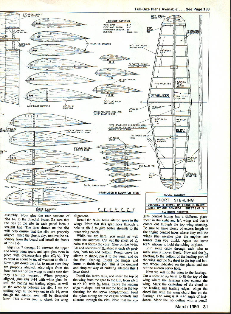
For me, the Sterling is one of those aircraft so plain as to be beautiful. It is rarely modeled. About 20 years ago I built an Avro Lancaster, which I still fly, so I decided to build the Sterling to the same scale. This resulted in a model with a 74 in wingspan and a 65 in fuselage. I powered it with four O.S. .10 FSR engines (four O.S. Max 15s could also be used) and four-channel control.
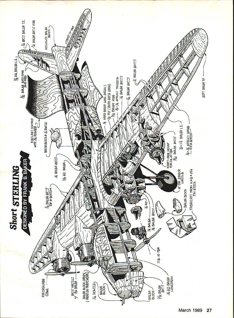
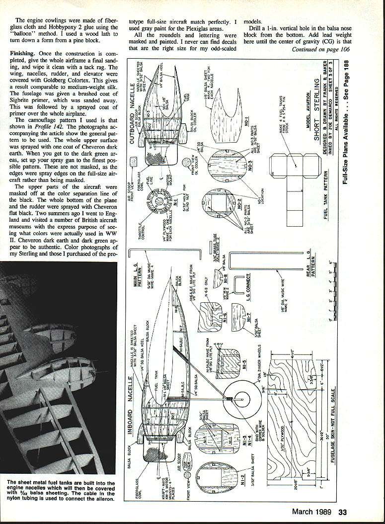
Designed by Frank B. Baker
- Four O.S. .10 engines (or O.S. Max 15)
- Four-channel control
- Model span: 74 in; fuselage: 65 in
Parts callouts (diagram labels)
- Make landing gear wires in 1/8" music wire.
- Wing retainer plate — 1/16" aluminum. Wing retainer plate attached to maple wing mount plates with 1/2" sheet-metal screws.
- Main wheels — side view.
- Fiberglass cowl
- Balsa block (nose)
- Soft balsa tip
- 1/4" balsa sheet
- 1/8" balsa sheet (top & bottom)
- Balsa ribs
- 1/8" balsa leading edge
- Balsa wing saddle
- Maple wing mount plates
- Servo rails
- Rudder & elevator pushrod cables
- Incidence
(Note: Full-page exploded view and detailed parts callouts/labels are diagram only.)
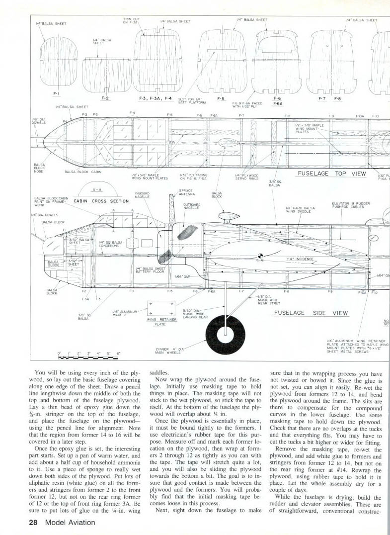
Fuselage
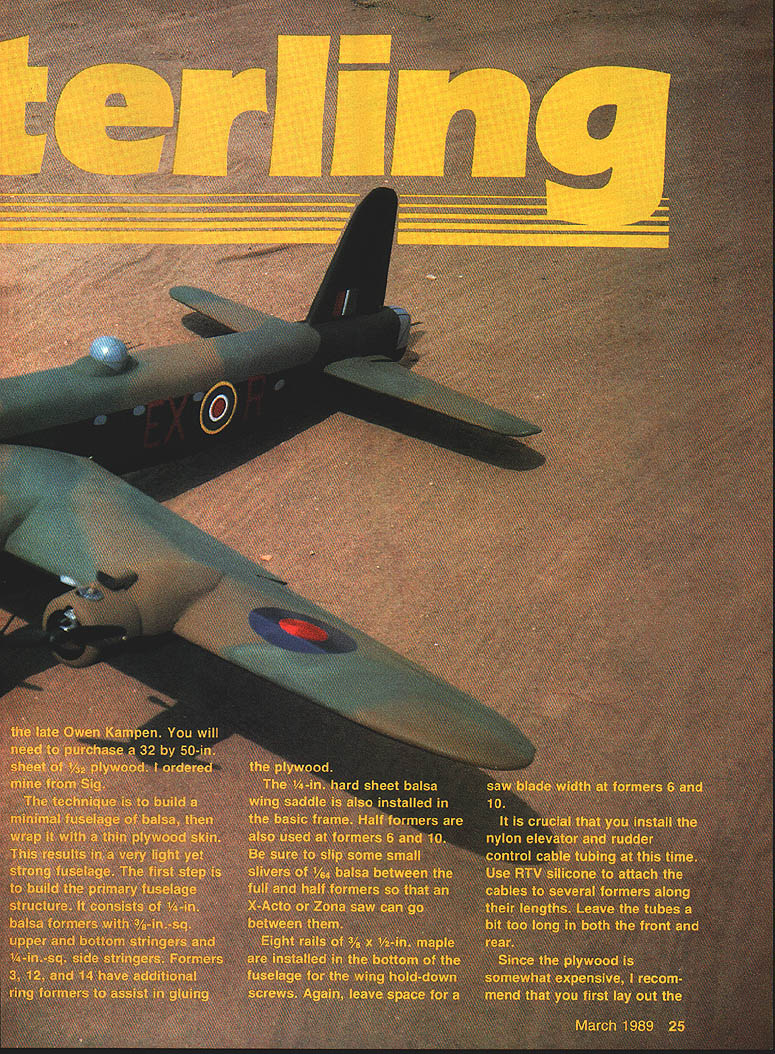
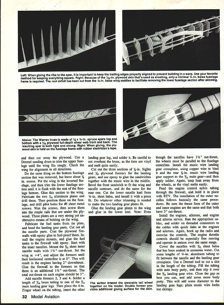
I used the rolled-plywood approach pioneered by the late Owen Kampen. You will need a 32 by 50 in sheet of 1/32" plywood (I ordered mine from Sig). The technique is to build a minimal balsa fuselage framework, then wrap it with thin plywood skin—resulting in a light yet strong fuselage.
Primary fuselage structure:
- 1/4" balsa formers
- 3/16" square upper and bottom stringers
- 1/4" square side stringers
- Formers 3, 12, and 14 have additional ring formers to assist in gluing the plywood
- 1/4" hard-sheet balsa wing saddle installed in the basic frame
- Half formers at formers 6 and 10 (slip small slivers of 1/64" balsa between full and half formers so a saw blade can pass)
Install eight rails of 3/8 x 1/2 in maple in the bottom of the fuselage for the wing hold-down screws. Leave space for a saw blade width at formers 6 and 10.
It is crucial to install the nylon tubing for elevator and rudder control cables at this time. Use RTV silicone to attach the tubing to several formers along their length. Leave the tubes a bit long fore and aft.
Since the plywood is expensive, first lay out the fuselage sheeting on a piece of thin, flexible cardboard to test fit and the location of cutouts. Draw a pencil line lengthwise down the middle of both the top and bottom of the fuselage plywood for alignment.
Sheeting and wrapping procedure:
- Lay a thin bead of epoxy glue along the 3/16" stringers on the top of the fuselage and place the fuselage plywood using the pencil line for alignment. Note: the region around former 14 (and to former 16) will be covered later.
- Set up a pan of warm water and add about 1/2 cup household ammonia. Wet both sides of the plywood thoroughly with a sponge.
- Apply lots of aliphatic resin (white glue) to the formers and stringers—especially around the wing saddle and the formers used to hold the ply (for example, former 2, former 3A, and former 12).
- Wrap the plywood around the fuselage. Initially use masking tape to hold things in place; masking tape will stick to itself if the plywood is wet.
- The bottom fuselage plywood will overlap slightly (about 1/4 in). Once the plywood is essentially in place, bind it tightly to the formers using electrician's rubber tape. Measure and mark the former locations on the plywood, then wrap formers 2 through 12 tightly. Rubber tape stretches and will help pull the plywood into good contact with the formers.
- Sight down the fuselage to ensure it has not been twisted or bowed. Re-wet plywood around formers 12–14 and bend around frame slits to compensate for compound curves of the lower fuselage; use masking tape to hold while checking for overlaps or tucks.
- Remove masking tape, re-wet plywood, add white glue to the formers and stringers, and rewrap with rubber tape. Let the assembly dry a couple of days.
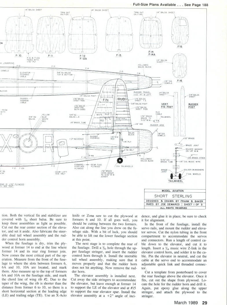
After drying:
- Build the rudder and elevator assemblies.
- Trim the plywood at former 14 to end at the line where former 14 and its rear ring former join.
- Measure from the front of the fuselage to locate the slots between formers 6/6A and 10/10A, and mark the chord line of wing rib #2. Because of wing taper, rib is shorter than the distance from former 6 to 10, leaving short horizontal sections at LE and TE.
- Use an X-Acto knife or Zona saw to cut the plywood at formers 6 and 10 and along the chord-line marking. Lift out the lower fuselage section.
Rear fuselage and controls:
- Drill a 3/32" hole through the upper fuselage stringer and insert the rudder control horn. Install the steerable tailwheel assembly and verify movement; then remove the rudder horn for further work.
- Cut away side stringers to accommodate the elevator but leave enough at former 14 to support the elevator leading edge and at former 15 to support the rear elevator spar.
- Install the elevator at +2° incidence and glue it in place, checking alignment.
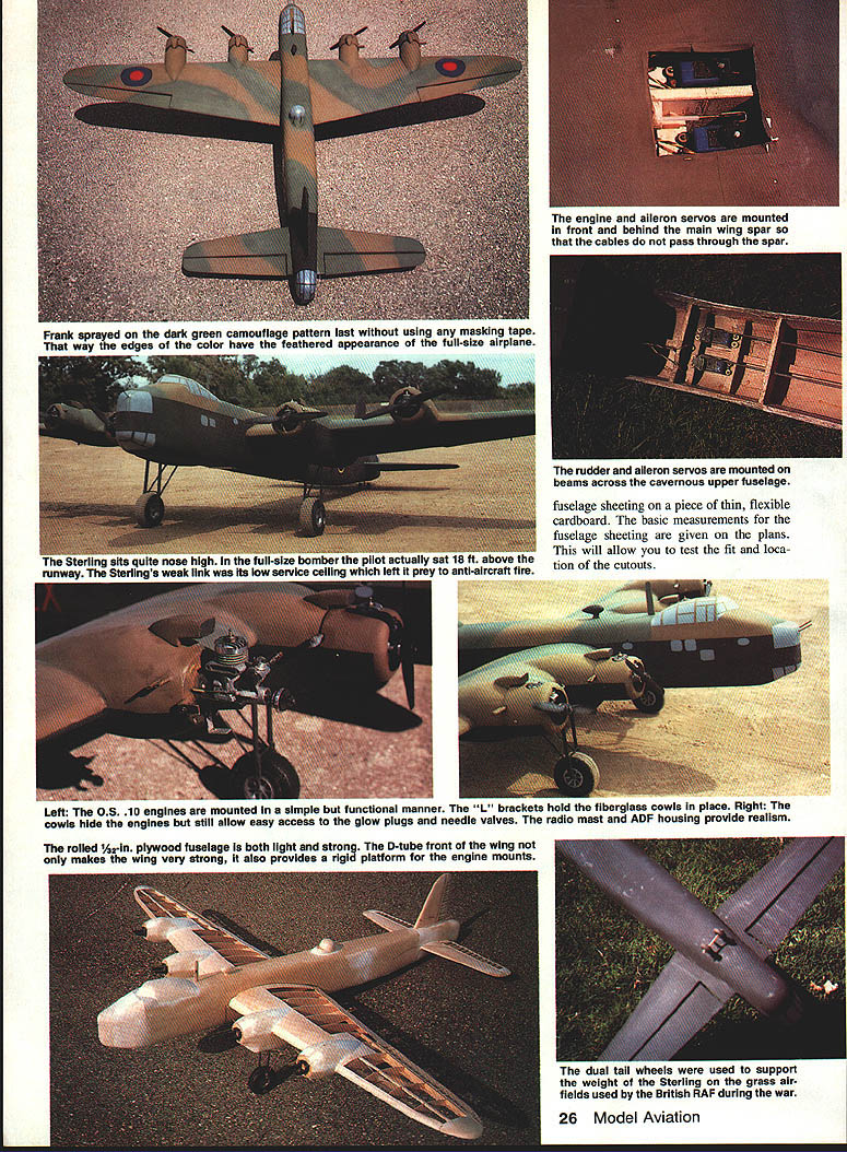
Front compartment and servos:
- Install servo rails and mount rudder and elevator servos. Cut the nylon tubing in the front compartment as needed for servos and connectors.
- Run a length of control cable to the elevator, cut to length, insert a 1/16" music-wire Z-link in the elevator control horn and solder it to the cable. Pin elevator in neutral; at the servo end use an adjustable quick link and threaded connector.
- Cut a posterboard template for the rear fuselage cover above the elevator, transfer to plywood, locate and drill the rudder-horn hole, then epoxy along the upper stringer and attach the plywood.
- Insert the rudder control horn from the bottom and install the 1/16" music-wire link to the tailwheel steering mechanism. Wrap the rudder control rod where it passes above the fuselage with masking tape so it cannot slip back down.
- Slip a proper length of control cable into the rudder tubing and solder the Z-link to the cable.
- Spot-glue the vertical fin to the fuselage, insert and glue the rudder control rod, and install the rudder hinge pins. Hold rudder neutral and install quick-link assembly at the servo end. Hook the rudder and elevator servos to a radio and exercise the controls—everything should move smoothly and have proper range.
Closing up the rear:
- Wet down the plywood, liberally apply glue to the formers, bend down the plywood, and use tape and pins to hold it in place.
- Cut out and glue the plywood for the bottom fuselage.
- Cut and glue the necessary front fuselage parts. Region from former 1 to 3 is covered with 3/32" sheet balsa; 4-in. sheet soaked in the ammonia-water solution covers this area easily.
Nose and cockpit:
- Carve nose and tail blocks to rough shape, glue them in place, then final shape and sand.
- Carve cockpit from a balsa block and fit to fuselage.
- Use spackling compound (e.g., Red Devil "Onetime") to fill cracks and joints, then sand with 220-grit paper.
- Carve upper turret coaming and attach. Install the balsa fairing between rudder and fuselage and the section of elevator that fits between the movable part and fuselage.
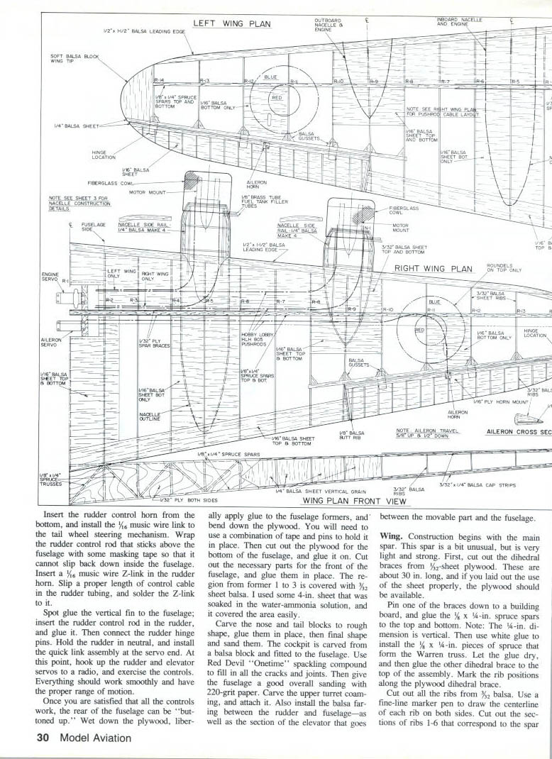
Wing
Wing construction begins with the main spar assembly. The spar is light and strong and incorporates a Warren truss.
Spar and dihedral braces:
- Cut dihedral braces from 3/32" sheet plywood (about 30 in long).
- Pin a brace to a building board and glue 1/8" x 1/4" spruce spars to top and bottom (1/4" dimension vertical).
- Use white glue to install 1/8" x 1/4" pieces of spruce for the Warren truss.
- When dry, glue the second dihedral brace and mark rib positions along the plywood dihedral brace.
Ribs and assembly:
- Cut all ribs from 3/32" balsa. Draw the rib centerline on both sides.
- Cut out the front and rear sections of ribs 1–6 as needed to fit the spar assembly.
- Glue the rear sections of ribs 1–6 to the dihedral brace, ensuring the tips of ribs in each panel form a straight line.
- When dry, install the front sections of ribs 1–6.
- Slip ribs 7–14 between upper and lower wing spars and spot-glue with cyanoacrylate (CyA). Build in about 1/4" of washout at rib 14.
- Sight down the ribs and from front and rear to ensure no warp. When aligned, glue ribs 7–14 with white glue.
- Install leading and trailing edges and webbing between ribs. I ran the trailing edge to rib 14 even though the aileron area will be discarded later to assist with alignment.
Ailerons:
- Build ailerons from 1/16" balsa core with 1/4" leading edge and 1/16" sheet sections at each rib position (top and bottom).
- Rough-carve, pin to the wing, finish shaping, install hinges and horns.
Wing sheeting and servo compartments:
- Install servo rails and sheet the top of the wing from the spar to the LE (rib 1 to rib 10) with 3/32" balsa.
- Carve the leading edge, cut the servo compartment hole in the top sheeting, and feed nylon tubing for engine controls and ailerons through the ribs.
- Note that engine-control tubing placement differs between right and left wings and exits through the top sheeting. Leave plenty of excess tubing length where it exits the wings (nacelles plus engines are longer than you think). Harden tubing with RTV silicone where it exits.
- Run some cable through each tube to ensure free movement.
- Add 3/32" sheeting to the bottom of the leading edge and 1/16" sheeting top and bottom where indicated on plans; cut the aileron-servo hole.
Fitting wing to fuselage:
- Cut a sheet of 3/8" balsa to fit the top of the wing where the fuselage sides contact the wing. Mark the centerline of the chord at the LE and TE and align to the fuselage chord line. The wing is set at +4° incidence.
- Mark rib outlines, drill holes for 1/4" dowels, making sure dowels pick up the wing ribs under the sheeting.
- Glue the wing saddle to the top of the fuselage. Dry-fit the wing and make shims to set dihedral and incidence. When set, glue the wing in place with epoxy or white glue and allow to dry.
Finishing the joint and wing-retainer plates:
- Trim the upper fuselage until the wing fits snugly (a Dremel sanding drum is useful).
- Trim the lower fuselage section (leave ~1/8" excess), invert the fuselage to fit the wing, then trim the lower section flush and glue it to the wing.
- Fabricate two 1/16" aluminum plates and drill pilot holes for 3/8" sheet-metal screws. Wax the screws, then screw them into the maple rails under the plywood. These plates are a strong, unobtrusive method of holding the wing.
Nacelles, landing gear and engines
- Fabricate fuel tanks from tin plate and bend landing-gear parts.
- Cut nacelle parts and coat plywood firewalls with epoxy to fuel-proof them.
- Install engine mounts and glue fuel tanks to the firewall with epoxy.
- Start with inner nacelles. Mount 3/32" sheet inner nacelle walls with 1.5° out-thrust. Set the wing at +4° and adjust formers until their horizontal centerline is at 0°; this results in engines having 2° downthrust. Glue firewall to formers with an additional 1.5° out-thrust so total out-thrust per engine is 3°.
- Add nacelle formers 2, 3 and 4.
Landing gear:
- Solder a length of 3/32" brass tubing to one 5/32" main landing-gear leg. Place the 4 in Zinger wheel on the tubing, insert the other leg, and solder—avoid overheating the brass as vinyl tires melt easily.
- Cut three sections of 1/8" Siglite and 1/32" plywood formers for the landing-gear sandwiches; epoxy them together with the music wire in the middle. Bevel front sandwich to fit wing and nacelle contours.
- Cut the lower nacelle keel from 1/4" sheet balsa and install with a press fit.
- Glue landing-gear plates to the wing and glue in the lower keel. Although nacelles have 1.5° out-thrust, wheels must be parallel to the fuselage centerline.
- Install music-wire landing-gear crosspiece, bind with copper wire to the rear 1/8" music-wire landing-gear support and the 3/32" main gear, then epoxy-solder—keep heat away from wheels.
- Feed engine-control nylon tubing through the firewall and hold with RTV.
Outer nacelles follow the same procedures as inner nacelles. Ensure thrust lines of outer and inner engines match and that both have 3° out-thrust.
- Install engines, ailerons, and engine and aileron servos.
- Run and solder threaded connectors to cables with quick links at the engines and ailerons. Hook up the radio and exercise controls; engine throttles should be free-moving and operate in unison over the same range.
Finishing touches to landing gear:
- Cover nacelles with 3/32" balsa soaked in ammonia water.
- Cut lengths of 1/4" aluminum tubing to fit between nacelle and landing-gear crosspiece; cut a slot along the tubing, fill with auto-body putty, slip over 3/32" landing-gear wire and close the gap with more body putty. This increases apparent diameter of the gear legs—plain music wire looks too skimpy.
Cowls:
- Engine cowlings were made from fiberglass cloth and Hobbypoxy 2 using the balloon method. I used a wood lath to turn a form from a pine block.
Finishing
- Give the whole airframe a final sanding and wipe with a tack rag.
- Wing, nacelles, rudder, and elevator were covered with Goldenrod Colortex (comparable to medium-weight silk).
- The fuselage received a brushed coat of Sigbrite primer which was sanded away, then the whole aircraft sprayed with primer.
- Camouflage: I used the pattern shown in Profile 142 and photographs of the full-size aircraft as reference. Upper surfaces were sprayed one coat of Chevron Dark Earth. For Dark Green areas, set the spray gun to the finest pattern—these were spray-edged rather than masked to match full-size finish.
- Mask upper parts at color separation line of black. Spray the whole bottom and the rudder with Chevron flat black. I used gray paint for Plexiglas areas.
- All roundels and lettering were masked and painted (decals at odd scales are often not available).
Add ballast:
- Drill a 1 in vertical hole in the balsa nose block from the bottom and add lead weight until center of gravity (CG) is at the location shown on the plans (I used about 8 oz). Plug the hole with balsa and repaint.
Flying
Starting engines:
- Start procedure: get the left outboard engine running at smooth near-peak rpm, idle it, and stop it with a cloth. Repeat for each engine. Top off tanks. Set throttle full open and start each engine left to right.
- Typically each engine starts on the first flip. I don't synchronize the engines; I may adjust the throttle of one that isn't smooth.
Takeoff options:
- Full-throttle running start: have someone give the plane a short running start. If too slow, the plane will veer (often sharply to the left); a steerable tailwheel helps.
- Progressive-throttle start: begin at half throttle, steer with the rudder, and as speed builds, add throttle.
In either case, let ground speed build, lift the tail, and let the Sterling roll a good distance before giving up-elevator to break ground. Avoid pulling off too early—premature liftoff causes wallowing, though it will usually settle down.
In flight:
- Once airborne the Sterling is reasonably fast, flies smoothly, and is majestic and realistic in the air.
Landings:
- Make a wide base leg and a long final approach. Pull throttles back for a steady descent. A few feet off the ground, pull throttles to idle for a wheel landing; it will roll before the tail settles.
- Best practice: land with all four engines running. The Sterling flies on three engines, but if one quits, keep the nose down and land as soon as practical.
I hope you enjoy the Sterling; it is an impressive aircraft both on the ground and in the air.
Transcribed from original scans by AI. Minor OCR errors may remain.

