
Simitar XV
Bill Evans
Photos by Bruce Robertson
THOUGH there are many "real neat" looking aircraft with eye appeal, the flying wing undoubtedly creates the greatest fascination and attention. I am sure of this because what happens at the flying field goes like this: When you arrive at the field the pits are bustling with normal activities related to flying conventional ships. Spectators are sitting in cars paying casual attention to flight activities and stirring a bit in the event of a good crash. However, when you crank up and take off your flying wing, other fliers come over and truthfully say "I never thought it would fly!" The spectators react by getting out of their comfortable seats, paying very close attention and comment with disbelief and wonderment.
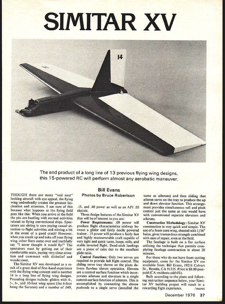
The Simitar XV was developed as a result of a great deal of first-hand experience with the flying wing concept and is number 14 in a long line of flying wing designs. Preceding designs include gliders with 4-, 5-, 6- and 10-foot wing spans (the 6-foot being the Saracen) and a number of .049, .15 and .40 power as well as an AFI .05 electric.
Those design features of the Simitar XV that will be of interest to you are:
Power Requirements: .09 power will produce flight characteristics midway between a glider and a fairly docile powered trainer. .15 power will produce a fairly fast and highly maneuverable craft capable of very tight and quick turns, loops, rolls, and stable inverted flight. Dead-stick landings are a piece of cake due to the excellent glide ratio.
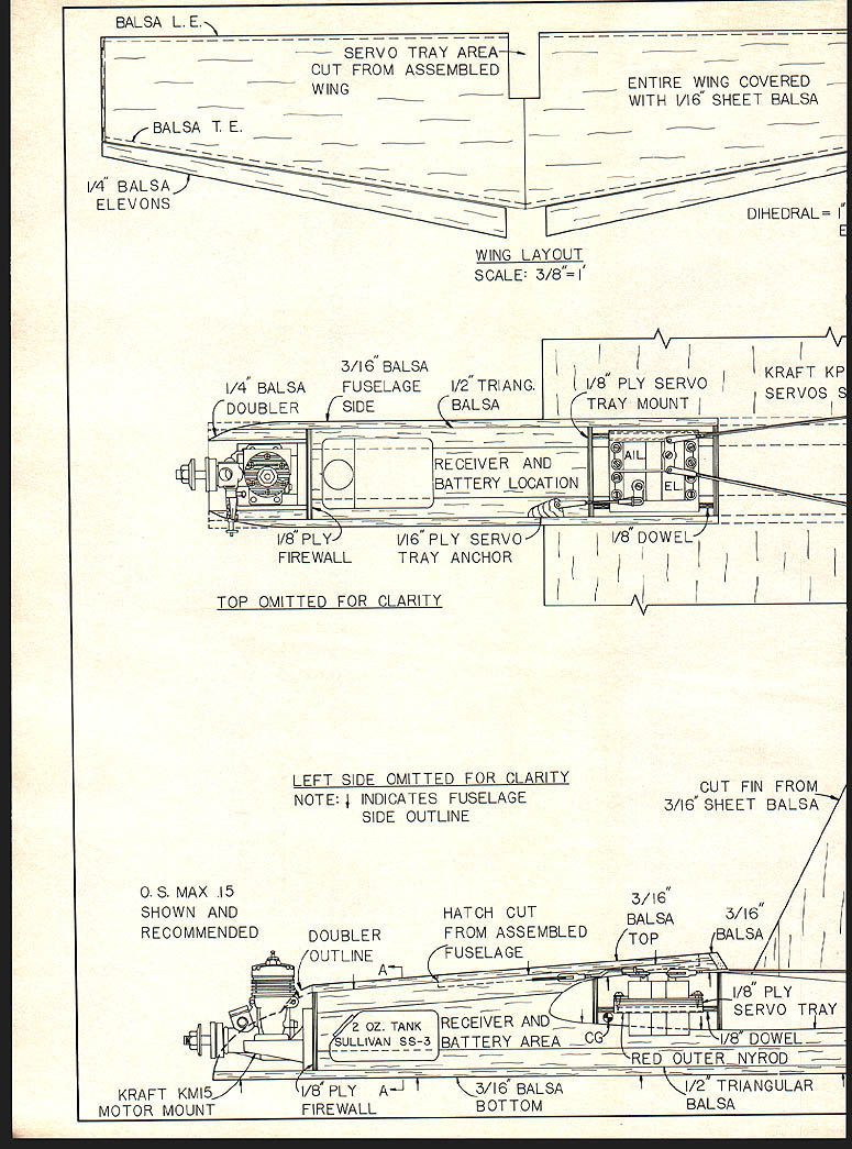
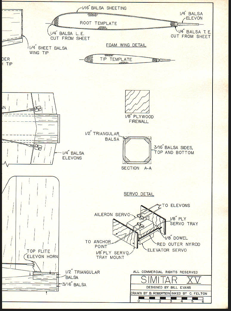
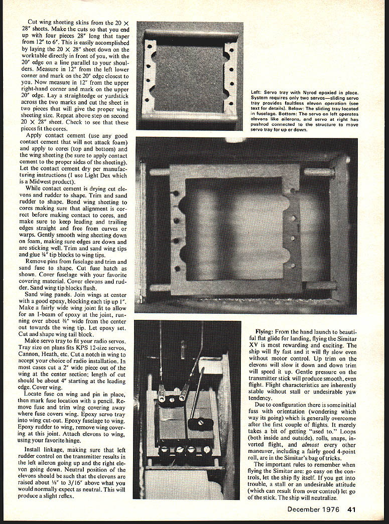
Control Functions: Only two servos are required to provide full flight control. The sliding servo tray shown on the plans delivers flawless elevon operation. Elevons are a control surface which incorporates ailerons and elevators in a single control-surface function. Aileron and elevator functions are accomplished by connecting the elevon pushrods to a single servo (installed the same as ailerons) and then sliding that elevator servo on the tray to produce the up and down elevator function. This arrangement provides simultaneous roll and pitch control just the same as one would have with conventional separate elevators and ailerons.
Construction Methodology: Simitar XV construction is very quick and simple. The use of a foam core wing, sheeted with 1/16" balsa, gives tremendous strength combined with ease of repair, even at the field. The fuselage is built on a flat surface utilizing the technique that permits completing fuselage construction in about 20 minutes.
For those who do not have foam cutting equipment, cores for the Simitar XV are available from: Bill Evans, 19216 Calvert St., Reseda, CA 91335. Price $8.00 postpaid (CA residents add 6%). Built according to the plans and following the instruction sequence below, your Simitar XV building project will result in a rewarding flight experience.
Simitar XV Construction
Glue and pin balsa leading edge to wing cores, making sure to keep the leading edge free of bends and curves. Glue and pin the trailing edge to the wing core; again make sure the trailing edge remains straight and free of curves — this is important due to the fact a nice straight trailing edge will make the elevons work freely. Set aside to dry.
Cut out fuselage parts, sides; mark location 1/16" BALSA SHEETING
ROOT TEMPLATE
1/4" BALSA L.E. CUT FROM SHEET
1/4" BALSA ELEVON
1/4" BALSA T.E. CUT FROM SHEET
1/4" SHEET BALSA WING TIP
FOAM WING DETAIL
TIP TEMPLATE
1/8" PLYWOOD FIREWALL
1/2" TRIANGULAR BALSA
SECTION A-A
3/16" BALSA SIDES, TOP AND BOTTOM
SERVO DETAIL
TO ELEVONS
AILERON SERVO
1/8" PLY SERVO TRAY
TO ANCHOR POINT
1/8" PLY SERVO TRAY MOUNT
1/8" DOWEL
RED OUTER NYROD
ELEVATOR SERVO
TOP FLITE ELEVON HORN
1/2" TRIANGULAR BALSA
3/16" BALSA
ALL COMMERCIAL RIGHTS RESERVED
SIMITAR XV
DESIGNED BY BILL EVANS
DRAWN BY B. ROBERTSON INKED BY C. FELTON of firewall), top, bottom, tail block, firewall, and cowl cheeks. Pin fuse bottom down on flat surface. Glue and pin left fuselage side to fuse bottom—same for right fuse side. Locate and drill motor mount holes and install blind nuts. Glue and pin firewall in place.
Cut two lengths of 1/2" balsa triangle stock to run from the rear of the firewall to the tail end of the fuse. Apply glue to two sides of the 1/2" balsa triangle and pin triangle in place at bottom corners of the fuse (where the sides and fuse bottom join). Push pins in through from the outside of the fuse. Glue in fuse tail block piece. Glue in 1/2" balsa triangles to the top inside edges of the fuse sides, pinning through the fuse sides from the outside. Glue and pin fuse top to 1/2" top triangles. Note the fuse top fits between the sides. That is, do not attempt to pull the fuse sides flush with the fuse top. The corner gap will be taken care of when you carve and sand the fuse to shape. Glue and pin cowl cheeks in place. Let fuse assembly dry.
Join wing sheeting (1/16" balsa sheet) using masking tape on one side to hold seam together, then run a bead of white glue on the seam edges (or more preferably run a bead of Zap on the seam). Join sheeting as described above to make two sheets 18" x 28". Remove pins from wing leading and trailing edges, then trim and sand leading and trailing edges as shown on plans so that the wing sheeting will fit nicely over the T.E. and L.E. Cut wing sheeting skins from the 20" x 28" sheets. Make the cuts so that you end up with four pieces 28" long that taper from 12" to 6". This is easily accomplished by laying the 20" x 28" sheet down on the worktable directly in front of you, with the 20" edge on a line parallel to your shoulders. Measure in 12" from the left lower corner and mark on the 20" edge closest to you. Now measure in 12" from the upper right-hand corner and mark on the upper 20" edge. Lay a straightedge or yardstick across the two marks and cut the sheet in two pieces that will give the proper wing sheeting size. Repeat above step on second 20" x 28" sheet. Check to see that these pieces fit the cores.
Apply contact cement (use any good contact cement that will not attack foam) and apply to cores (top and bottom) and the wing sheeting (be sure to apply contact cement to the proper sides of the sheeting). Let the contact cement dry per manufacturing instructions (I use Light Dex which is a Midwest product).
While contact cement is drying cut elevons and rudder to shape. Trim and sand rudder to shape. Bond wing sheeting to cores making sure that alignment is correct before making contact to cores, and make sure to keep leading and trailing edges straight and free from curves or warps. Gently smooth wing sheeting down on foam, making sure edges are down and are sticking well. Trim and sand wing tips and glue 1/4" tip blocks to wing tips.
Remove pins from fuselage and trim and sand fuse to shape. Cut fuse hatch as shown. Cover fuselage with your favorite covering material. Cover elevons and rudder. Sand wing tip blocks flush.
Sand wing panels. Join wings at center with a good epoxy, blocking each tip up 1". Make a fairly wide wing joint fit to allow for an I-beam of epoxy at the joint, running over about 1/8" wide from the center out towards the wing tip. Let epoxy set. Cut and shape wing tail block.
Make servo tray to fit your radio servos. Tray size on plans fits KPS 12-size servos, Cannon, Heath, etc. Cut a notch in wing to accept your choice of radio installation. In most cases cut a 2" wide piece out of the wing at the center section; length of cut should be about 4" starting at the leading edge. Cover wing.
Locate fuse on wing and pin in place, then mark fuse location with a pencil. Remove fuse and trim wing covering away where fuse covers wing. Epoxy servo tray into wing cut-out. Epoxy fuselage to wing. Epoxy rudder to fuse, remove wing covering at this joint. Attach elevons to wing, using your favorite hinge.
Install linkage, making sure that left rudder control on the transmitter results in the left aileron going up and the right aileron going down. Neutral position of the elevons should be such that the elevons are raised about 1/8" to 3/16" above what you would normally expect as neutral. This will produce a slight reflex.
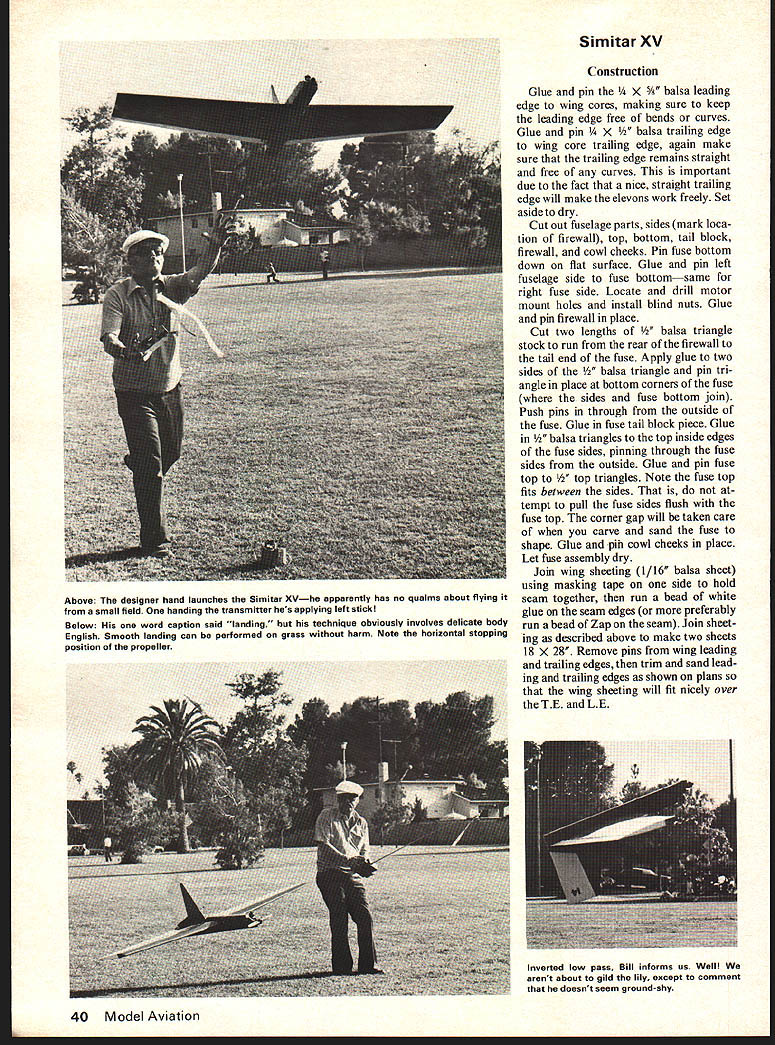
Flying: From the hand launch to a beautiful flat glide for landing, flying the Simitar XV is most rewarding and exciting. The ship will fly fast and it will fly slow even without motor control. Up trim on the elevons will slow it down and down trim will speed it up. Gentle pressure on the transmitter stick will produce smooth, even flight. Flight characteristics are inherently stable without stall or undesirable yaw tendency.
Due to configuration there is some initial fuss with orientation (wondering which way it's going) which is generally overcome after the first couple of flights. It merely takes a bit of getting "used to." Loops (both inside and outside), rolls, snaps, inverted flight, and almost every other maneuver, including a fairly good 4-point roll, are in the Simitar's bag of tricks.
The important rules to remember when flying the Simitar are: go easy on the controls, let the ship fly itself. If you get into trouble, a stall or an undesirable attitude (which can result from over control) let go of the stick. The ship will neutralize.
Transcribed from original scans by AI. Minor OCR errors may remain.

