
A Simple Glow Plug Battery Box
By Col. P. J. Render
Introduction
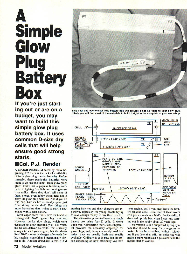
A major problem for beginning RC fliers is the lack of availability of fresh glow‑plug starting batteries. Commercial glow‑plug batteries were made for a single use and are not widely stocked, so new engines are often started with stale cells. Rechargeable Ni‑Cd batteries are an alternative but deliver only 1.2 V (glow plugs are designed for 1.5 V), must be recharged frequently, and their chargers and batteries can be expensive.
This simple battery box uses four common D‑size dry cells in parallel to provide the amperage needed for glow plugs. The parts are inexpensive (often found in the junk pile), construction is straightforward, and the box can be made without soldering (though soldering improves long‑term reliability). The design below uses a simplified finger‑spring system that is easy for beginners to build.
Materials
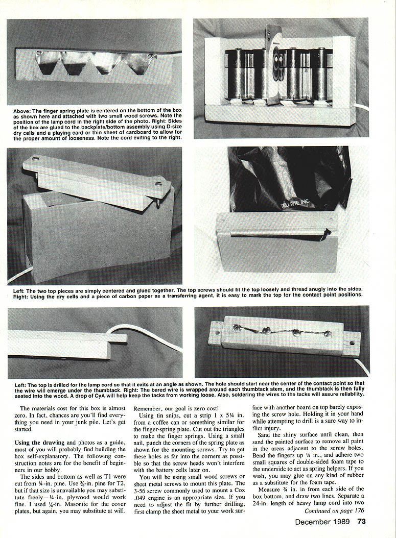
- Wood: 3/4‑in. pine for sides, bottom and top (T1). Use 3/8‑in. pine for T2; if unavailable, substitute 1/4‑in. plywood or similar. 1/8‑in. Masonite for cover plates (optional).
- Strip of thin sheet metal (e.g., coffee can) about 1 x 5‑1/4 in. for the finger‑spring plate.
- Tin snips, small nail (for punching corners), sandpaper.
- Small wood or sheet‑metal screws (3‑56 size is appropriate for mounting the spring plate).
- Heavy lamp cord (24 in. length; you will separate the conductors and use about 24 in. of cord overall).
- Thumbtacks (4) for top contacts; sand to clean paint.
- Double‑sided foam tape or small rubber pieces for spring helpers.
- Wood glue (or thick cyanoacrylate (CyA) or five‑minute epoxy).
- Solder and soldering iron (optional but recommended).
- Drill and bits: 1/16‑in., 1/8‑in. and 3/8‑in. drills.
- Two 1/4‑in. screws for top assembly.
- Carbon paper (or similar to mark contact points).
- Glow‑plug clip (or small two‑prong plug from an electronics store as an alternative).
- Fuel‑proof paint (optional).
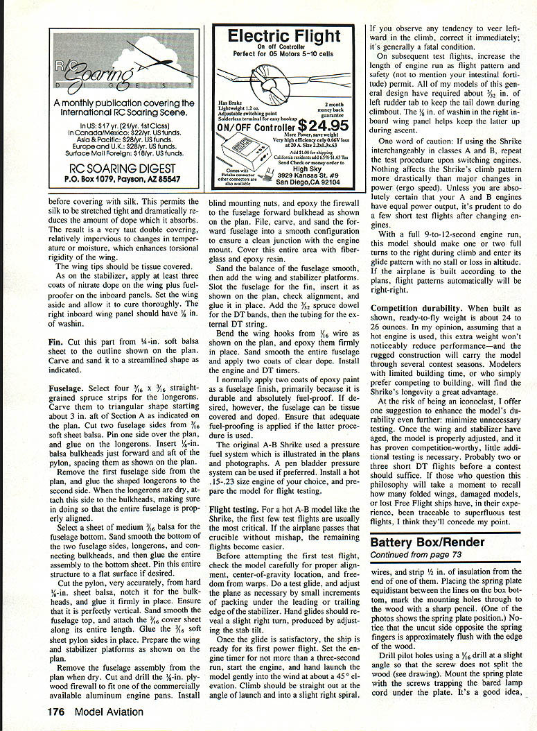
Finger‑spring plate
- Cut a 1 x 5‑1/4‑in. strip from a coffee can or similar thin sheet metal using tin snips.
- Cut out triangular sections to form the finger springs.
- Punch the corners of the spring plate with a small nail; place the screw holes near the corners so screw heads won't interfere with the cells.
- Sand the shiny surface clean and sand painted areas around the screw holes to remove paint.
- Bend the spring fingers up about 1/4 in.
- Adhere two small squares of double‑sided foam tape to the underside of the plate as spring helpers (or glue rubbery substitutes).
Wiring and mounting the spring plate
- Measure 3/4 in. from each side of the box bottom and draw two lines to locate the spring plate.
- Separate the conductors of the 24‑in. heavy lamp cord as needed. Strip and tin the ends where they will be soldered.
- Place the spring plate equidistant between the lines on the box bottom and mark the mounting holes through to the wood with a sharp pencil. Note: the uncut side opposite the spring fingers should be approximately flush with the edge of the wood.
- Drill pilot holes with a 1/16‑in. drill at a slight angle so the screws will not split the wood.
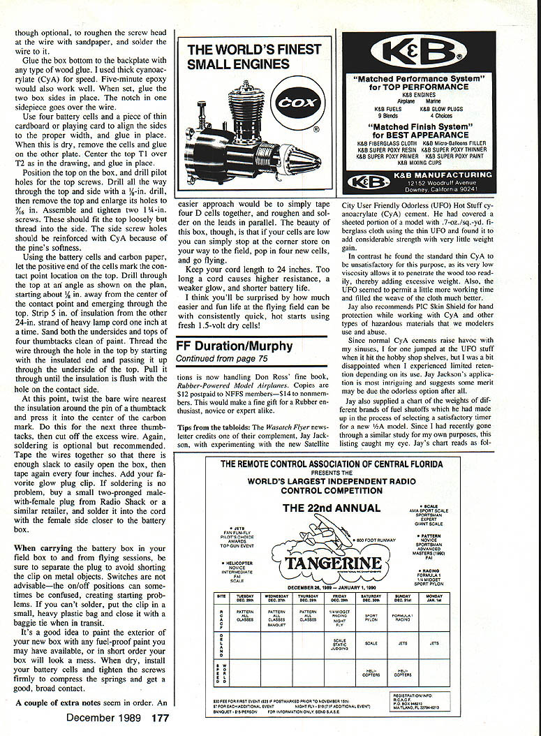
- Mount the spring plate under the screws, trapping the bared cord conductors under the plate. Solder the wires to the thumbtacks (or to the plate where appropriate) for reliability and drop a little CyA to keep tacks from working loose.
Box assembly
- Glue the box bottom to the backplate using wood glue, thick CyA or epoxy. When set, glue the two box sides in place. The end sidepiece should go over the wire where it exits.
- Use four D cells and a piece of thin cardboard or a playing card to align the sides to the correct width; glue and let dry.
- Remove the cells and glue on the remaining front or cover plate.
- Center the top (T1) over T2 as in the plan and glue in place.
- Position the top on the box and drill pilot holes for the top screws: drill through the top and side completely with a 1/8‑in. drill, then remove the top and enlarge the holes in the top to 3/8 in.
- Assemble and tighten two 1/4‑in. screws. These should fit the top loosely but thread into the side. Reinforce the side screw holes with CyA because pine is soft.
Top contact installation
- Place the battery cells on the top (positive ends up) and use carbon paper to mark the contact point locations on the top surface.
- For each contact, drill through the top at an angle, starting about 1/8 in. away from the center of the contact mark and emerging through the top as shown in the plan.
- Strip about 5 in. of insulation from the cord, exposing the bare conductors near the top end as needed.
- Sand the tops and undersides of the four thumbtacks clean of paint. Thread the wire up through the angled holes from the underside of the top and pull the insulation flush with the hole on the contact side.
- Twist the bare wire nearest the insulation around the pin of a thumbtack and press the tack into the center of the carbon mark. Repeat for all four thumbtacks. Solder the wire to each tack if possible.
- Tape the wires together, leaving enough slack so the box opens easily; tape the lead every four inches to keep it tidy.
- Add your glow‑plug clip. If you cannot solder, an alternative is a small two‑prong male‑with‑female plug (female side closer to the battery box) bought from an electronics retailer; solder the plug into the cord.
Finishing and use
- Paint the exterior with fuel‑proof paint to protect the box and improve appearance.
- Install four D cells, tighten the screws to compress the finger springs for a broad, reliable contact.
- Keep the cord length to about 24 inches. Longer cord increases resistance and weakens glow and battery life.
- When transporting the box, separate the plug or secure the clip to avoid shorting against metal objects. Avoid an on/off switch—the positions can be misleading and create starting problems. If you can't solder the clip, place it in a small heavy‑plastic bag and close it with a tie during transit.
Notes and alternatives
- A simpler approach is to tape four D cells together and solder leads in parallel; however, the box makes it easy to replace cells at the field if they’re low.
- Soldering connections where possible will improve durability as metals oxidize over time.
I think you'll be surprised how much easier and more fun flying becomes with consistently quick, hot starts using fresh 1.5‑volt dry cells!
Transcribed from original scans by AI. Minor OCR errors may remain.

