
Simple Method for Drawing Small Angles
Have you ever wanted to strangle designers who call out 1-degree right-thrust, or 1-1/2 degrees incidence?
Warren Shipp
AT ONE TIME or another, most of us have tried to draw our own plans for a model using published drawings. All too often, incidence and dihedral angles are given in degrees. This is especially true in the case of 3-views of real airplanes. These angles are almost universally small, from 1° to 4°, rarely ever large. To draw such small angles accurately is practically impossible using the small protractors most of us have.
The following method was developed for drawing small angles simply and accurately. At first glance, the process may seem involved and complicated. However, try it out a few times on scrap paper on several small angles, and you will find that the procedure is quite simple and accurate. The accompanying table is worked out in half-degree increments to furnish as complete data as possible. By reversing the steps, the method may also be used to determine the number of degrees of an angle when such data is not given on a drawing. The table was based on the following computations.
Formula: C = 2 × π × r, where C = 360 inches, π = 3.14159, and r is unknown. Completing the computation, we find that a circumference of 360.00045 inches has a radius of 57.2959 inches. Rounding this out for simplicity, a circumference of 360 inches has a radius of 57.3 inches, or 57-5/16 inches. Substituting degrees for inches in the circumference, we find that a circumference of 360 degrees will have a radius of 57-5/16 inches. For our purposes, this radius will hereafter be referred to as the base line. The table which resulted from the computations was carried out to the nearest 1/16th of an inch. Angles larger than 10° may be easily worked out. Odd degree dimensions may be interpolated from the table.
The following illustrated example demonstrates the method of using the table and lists the procedures required to draw a small angle.
Let us assume that we have a small 3-view drawing of a real airplane and we want to draw plans for a model much larger than the 3-view. The drawing indicates that the wing is set at a 2° angle of incidence. In the illustration, the procedure steps are indicated by circled numbers.
Procedure
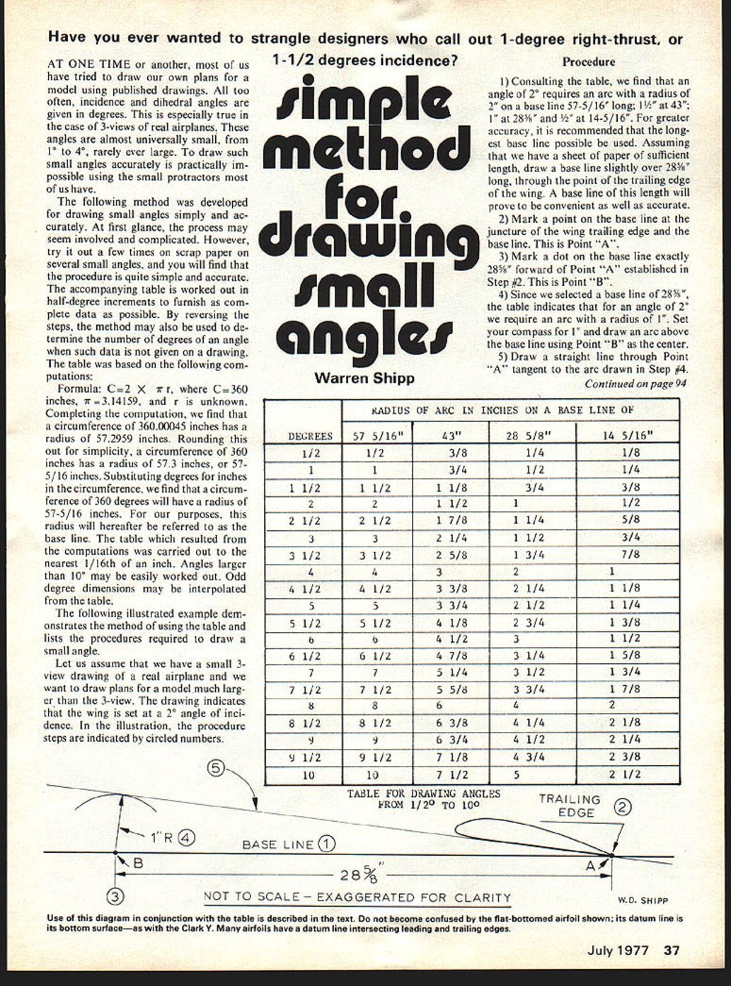
1) Consulting the table, we find that an angle of 2° requires an arc with a radius of 2" on a base line 57-5/16" long; 1 1/2" at 43"; 1" at 28 5/8"; and 1/2" at 14-5/16". For greater accuracy, it is recommended that the longest base line possible be used. Assuming that we have a sheet of paper of sufficient length, draw a base line slightly over 28 5/8" long, through the point of the trailing edge of the wing. A base line of this length will prove to be convenient as well as accurate.
2) Mark a point on the base line at the juncture of the wing trailing edge and the base line. This is Point "A".
3) Mark a dot on the base line exactly 28 5/8" forward of Point "A" established in Step #2. This is Point "B".
4) Since we selected a base line of 28 5/8", the table indicates that for an angle of 2° we require an arc with a radius of 1". Set your compass for 1" and draw an arc above the base line using Point "B" as the center.
5) Draw a straight line through Point "A" tangent to the arc drawn in Step #4.
RADIUS OF ARC IN INCHES ON A BASE LINE OF DEGREES 57 5/16" 43" 28 5/8" 14 5/16" 1/2 1/2" 3/8" 1/4" 1/8" 1 1" 3/4" 1/2" 1/4" 1 1/2 1 1/2" 1 1/8" 3/4" 3/8" 2 2" 1 1/2" 1" 1/2" 2 1/2 2 1/2" 1 7/8" 1 1/4" 5/8" 3 3" 2 1/4" 1 1/2" 3/4" 3 1/2 3 1/2" 2 5/8" 1 3/4" 7/8" 4 4" 3" 2" 1" 4 1/2 4 1/2" 3 3/8" 2 1/4" 1 1/8" 5 5" 3 3/4" 2 1/2" 1 1/4" 5 1/2 5 1/2" 4 1/8" 2 3/4" 1 3/8" 6 6" 4 1/2" 3" 1 1/2" 6 1/2 6 1/2" 4 7/8" 3 1/4" 1 5/8" 7 7" 5 1/4" 3 1/2" 1 3/4" 7 1/2 7 1/2" 5 5/8" 3 3/4" 1 7/8" 8 8" 6" 4" 2" 8 1/2 8 1/2" 6 3/8" 4 1/4" 2 1/8" 9 9" 6 3/4" 4 1/2" 2 1/4" 9 1/2 9 1/2" 7 1/8" 4 3/4" 2 3/8" 10 10" 7 1/2" 5" 2 1/2"
TABLE FOR DRAWING ANGLES FROM 1/2° TO 10° In the illustration, a simple flat-bottomed airfoil is shown. However, symmetrical airfoils and other types should be drawn according to the tables of coordinates for those particular airfoils, with the line (Step #5) as the mean camber, or in some cases, 0% of the chord. In most cases, the base line will be parallel to the thrust line. For negative angles of incidence (Curtiss Hawk top wing, some horizontal stabilizers, etc.), the line drawn in Step #5 would be below the base line.
Transcribed from original scans by AI. Minor OCR errors may remain.

