
Simple Structural Test Techniques for RC Aircraft
Everyone wants to design and build airplanes that are safe for all flight conditions. Ground testing, as described here (and in other articles to follow), will tell the story before the plane gets into the air.
George M. Myers
I have never had so many positive responses so quickly as I did after offering simple structural test techniques in the April 1986 "Radio Technique" column. To quote the Sierra Silent Soarers' newsletter, "O boy, O boy, George, George! We're interested." I received many similar letters from modelers and vendors, and I appreciate their kind words.
Our editor/publisher, Carl Wheeley, prefers to treat this subject separately from "Radio Technique," so let's get started.
Let me say at the outset that I will demonstrate simplified procedures. Many refinements are possible and are used when testing man-carrying aircraft; those refinements are expensive. I'm showing procedures that can be followed with very few special tools and at minimum expense. But inexpensive is no excuse for careless work. A thing worth doing at all is worth doing right.
Why test?
We test to find hidden flaws, to build confidence in the aircraft, and to save time and money. The motto of the test engineer is: "Get the right answers on purpose."
What is a test? Four essential elements
There are four essential elements common to every test:
- Test specimen (the airplane or component under test)
- Test loads (the forces or conditions applied)
- Test setup (how the specimen is supported and instrumented)
- Test procedure (the step-by-step method of applying loads and observing results)
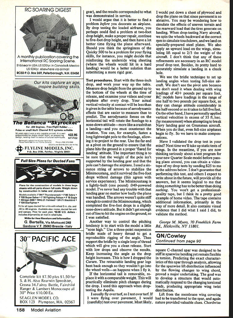
If you expect to profit from testing, include some instrumentation to collect data, analyze that data, and write a report so you won't forget what happened. A complete test begins with a test plan and ends with a test report.
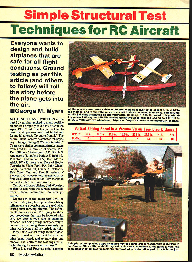
Although planning is important (don't skip it), we'll begin with a simple example: drop testing. Dropping an airplane onto its landing gear tests the landing gear and everything on and in the airplane that could be damaged by landing shock loads.
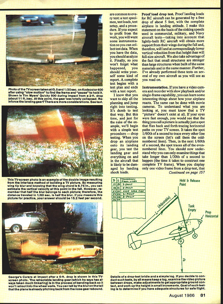
Vertical sinking speed in a vacuum versus free drop distance
- 3 in: 4 ft/sec
- 6.7 in: 6 ft/sec
- 11.9 in: 8 ft/sec
- 18.6 in: 11 ft/sec
- 28.6 in: 12 ft/sec
- 38.5 in: 14 ft/sec
- 4 ft: 16 ft/sec
- 5 ft: 18 ft/sec
Note: Actual vertical velocity at contact will be less than these vacuum values because of aerodynamic effects.
Instrumentation
A video camera/recorder with slow playback and/or single-frame capability can reveal interesting things about how your airplane reacts during a test; movie cameras can be used as well. To understand what you see on a TV or videotape, remember that a TV picture is constructed by a spot tracing horizontal lines. The spot traces odd-numbered lines in one 1/60th-second field and even-numbered lines in the next 1/60th-second field. Therefore you can only examine events that take longer than 1/30th of a second by watching continuous video. Displaying a single video frame or using slow-motion/single-frame playback lets you examine shorter-duration events.
Shorter camera exposures (1/90th to 1/200th second) reduce motion blur relative to standard TV or movie-camera exposures (common movie-camera exposure ~1/40th second). Some home movie cameras can be synchronized with strobe units providing very short exposures (as short as 1/50,000th second) to freeze rapid motion.
That's enough about simple instrumentation for these tests.
Proof load drop test
Proof landing loads for RC aircraft can be generated by a free drop of about five feet with the complete airplane in landing attitude. This guideline is based on sinking speeds used in commercial, military, and Navy aircraft tests, adjusted for:
- The greater support small, lightly built RC aircraft derive from their wings during a fall (reducing vertical velocity at contact), and
- The generally higher strength-to-size ratio of small structures built from the same materials.
I have performed these tests on several of my own aircraft and will describe examples below.
A sample test
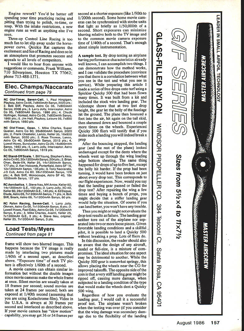
I performed a series of free drops onto turf using a Spickler Quicky 500 that had been flown many times. It was kit-built and used the stock wire landing gear. The videotape shows that at a two-foot gear height, the gear let the belly of the fuselage hit the ground. The plane then bounced about a foot into the air, hit again on the tail skid, then slammed down and bounced a couple more times on the wheels. Experienced Quicky 500 fliers will testify that a landing like that will often break a prop.
After the bouncing stopped, the landing gear and the rest of the plane looked undamaged except for dents where the prop chewed the wing leading-edge bottom sheeting. The same results occurred for drops up to five feet, particularly when the belly made a harder impact. If the prop had been fitted more tightly, it likely would have been broken on nearly every drop test. This corresponds to what we see in service.
Would you say the landing gear passed or failed? After repairing the wing several times and replacing props, you might decide a stiffer landing gear would help. On the other hand, a very stiff gear might be ripped off in an extreme landing, causing more damage than a springy gear that merely dents a wing. Aircraft design is a mixture of compromises.
I would call the Quicky 500 a successful proof test: the airplane didn't suffer major structural failure (the wing damage was secondary to the flexibility of the landing gear), and the results corresponded to service experience.
It's better to find a problem before you decorate an airplane. By drop-testing the loaded airframe, you might find a problem at a two-foot drop height, make a repair, continue to five feet, and then have a much more enjoyable time flying.
Test procedures
Start with a small drop and work up. Specific guidance:
- Start with a three-inch drop and work your way up the table of drop heights.
- Measure drop height from the ground to the bottom of the wheels at the instant of release.
- Examine video and inspect the airplane after every drop.
- Remember aerodynamic effects will reduce the actual vertical velocity at contact.
Controlling pitch attitude during the drop:
- Use a long, lightweight pole or stabilizer projecting to the rear and use the far end as a pivot to ensure a proper "flared-for-landing" attitude. Ensure the pole's weight is not supported by the landing gear and the pole can't damage the airplane.
- I used a six-ounce string of arrows to stabilize a Minimustang; it survived five-foot drops without damage. The arrows weren't quite stiff enough to keep the Minimustang perfectly level, but they kept it from hitting the engine.
- Use a three-point suspension bridle made of heavy thread to obtain reproducible rigging of the angle, then suspend the bridle with a single loop for a clean release. Start nose-high for small drops and increase the angle as drop height increases. This is how I dropped the Curare.
- If the horizontal tail is removable, replace it with a comparable weight to eliminate pitch changes during the drop (I used this for testing the Aquila).
Surface considerations:
- Test over the surface you normally fly on. I usually fly over turf, so I test over turf.
- If you fly over pavement, consider using a sheet of plywood to protect the airplane from abrasive pavement.
- Simulating uneven terrain or rearward tire loads is difficult in simple drop tests and generally not necessary for RC model proof drops. (Full-scale/Navy tests sometimes spin wheels to simulate touchdown and land on prepared plates, and apply wing loads simulating lift, but those refinements are rarely needed for hobby testing.)
Notes on scale and loads:
- We use bridles to set landing angles on full-size aircraft and don't need pivot arms because of higher wing loadings. RC models have much lower loadings and can change attitude considerably in the half-second or so it takes to fall five feet.
- In heavy-duty testing, vertical velocities in excess of 35 ft/sec have been applied to break full-scale landing gear; at those speeds, even full-size airplanes can start to fly on impact, so compensations are necessary.
Validation and videotape offer
I tested and validated the drop-test method on models whose flight performance was already known. The correlation between test results and service experience convinced me the method is useful.
If you are planning a test program for a new Quarter Scale model and want to see examples, you can obtain a videotape of my drop tests. Send $25 to the address below. The tape is a home video (not professional quality) but shows additional detail and visual evidence of the tests described.
George M. Myers 70 Froehlich Farm Rd. Hicksville, NY 11801
Transcribed from original scans by AI. Minor OCR errors may remain.

