

Simple Structural Test Techniques for RC Aircraft
Our look at model structures this month is about strengths and weaknesses of the balsa used in our planes. Part 2.
George M. Myers
Scope and approach
So far as I know, there is no college course in test engineering, and this column is not intended to serve in its place. An approach at that level would have too many pre- and co-requisites in terms of mathematical skills, physics, chemistry, geometry, economics, law, drafting standards, machine shop practices, and so on. In this series I will concentrate on structural test techniques for RC models, with digressions into related subjects when I think it is necessary, keeping the mathematics simple. This is the first digression.
All structural testing depends on knowledge of two things: applied loads and strength of materials. Load information comes from many sources, including:
- The geometry of the structure
- The aerodynamics of the air-passage surfaces (e.g., wind tunnel tests)
- The maneuvering characteristics required of the airplane
- Landing loads
- Ground handling loads
- Engine vibrations
- Environmental loads (temperature, humidity, fuel soaking)
- Considerations of transportation and storage
We are not going to consider applied loads today.
Information on strength of materials comes from laboratory testing of sample pieces of the material—and from no other place. Strength-of-materials information is collected in books. Let's check a few of them.
What is this stuff called wood?
In June 1944, the U.S. Department of Agriculture, Forest Service, Forest Products Laboratory (Madison, WI), in cooperation with the University of Wisconsin, released Report No. 1511, Strength and Related Properties of Balsa and Quipo Woods. In June 1945 the same group released Report No. 1528, Elastic properties of Wood, The Young's Moduli of Rigidity and Poisson's Ratios of Balsa and Quipo.
The Army-Navy-Civil Committee on Aircraft Design Criteria issued ANC-18, Design of Wood Aircraft Structures, over a period of years. I have a copy dated 1944 issued by the U.S. Government Printing Office, Washington, DC, and tables from a later edition dated June 1951. These copies have been an essential part of my modeling kit ever since I obtained them.
I doubt that any of the above are still available, but the data on strength of wood is as valid today as it was then, so I have presented some curves which summarize some of that data for you. A trip to any decent college library should reveal dozens of newer books containing the same old information.
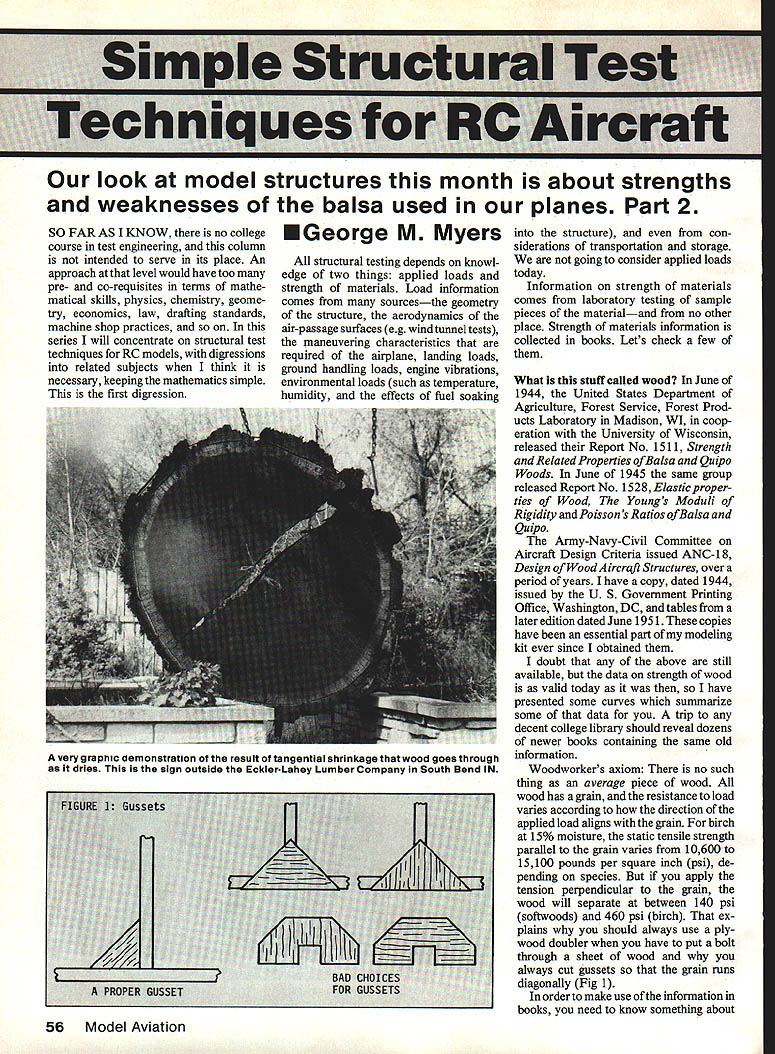
Woodworker's axiom: There is no such thing as an average piece of wood. All wood has a grain, and the resistance to load varies according to how the direction of the applied load aligns with the grain. For birch at 15% moisture, the static tensile strength parallel to the grain varies from 10,600 to 15,100 pounds per square inch (psi), depending on species. But if you apply the tension perpendicular to the grain, the wood will separate at between about 140 psi (softwoods) and 460 psi (birch). That explains why you should always use a plywood doubler when you have to put a bolt through a sheet of wood and why you should cut gussets so that the grain runs diagonally.
How tests are conducted
In order to make use of the information in books, you need to know something about how the tests were conducted. The first thing you have to know is that wood bends (yields) before it breaks. The highest stress that wood can resist without permanent bending is called its "proportional limit." The highest service loads should not apply stresses which exceed proportional limit stresses.
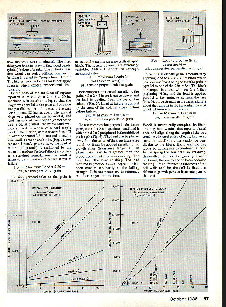
In the case of the modulus of rupture reported in ANC-18, a 2 × 2 × 30-in. specimen was cut from a log so that the length was parallel to the grain and one side was parallel to a radial. It was laid across two supports 28 inches apart. The annual rings were placed "on the horizontal," and load was applied from the pith (center of the tree) side. A central transverse load was then applied by means of a hard maple block 3 13/16 in. wide, with a nose radius of 3 in. over the central 2 1/8 in. arc and joined by 2-in. radius arcs on each side (see Fig. 2). For reasons I won't go into now, the load at failure (in pounds) is multiplied by the beam dimensions (before failure) according to a standard formula, and the result is taken to be a measure of tensile stress at failure.
- Fbu = Maximum Load × 5.25 = ____ psi, tension parallel to grain
Tension perpendicular to the grain is measured by pulling on a specially shaped block. The results obtained are extremely variable. ANC-18 reports an average measured value.
- Ftu = Maximum Load / (2 × Cross-Section Area) = ____ psi, tension perpendicular to grain
For compression strength parallel to the grain, a 2 × 2 × 8 beam is cut as above, and the load is applied from the top of the column (see Fig. 3). Load at failure is divided by the area of the column's cross section before failure.
- Fcu = Maximum Load / 4 = ____ psi, compression parallel to grain
To test compression perpendicular to the grain, use a 2 × 2 × 6 specimen and load it with a steel 2 × 2 pad placed in the middle of the bench (see Fig. 4). The load can be placed away from the center of the tree (transverse radial), or it can be applied parallel to the growth rings (transverse tangential). In either case, any load greater than the proportional limit produces crushing. The more load, the more crushing. The load required to produce a 1/10-in. depression has been chosen arbitrarily as the failing strength. It is not necessary to reference radial or tangential direction.
- Fcu (perpendicular to grain) = Load to produce 1/10-in. depression / 4 = ____ psi, compression perpendicular to grain
Shear parallel to the grain is measured by applying load to a 2 × 2 × 2.5 block which has been cut from the log so that the grain is parallel to one of the 2-in. sides. The block is clamped in a vise with the 2 × 2 face projecting 3/4 in., and the load is applied parallel to the grain, 3/8 in. from the vise (see Fig. 5). Since strength in the radial plane is about the same as in the tangential plane, it is not differentiated in reports.
- Fsu = Maximum Load / 4 = ____ psi, shear parallel to grain
Wood structure and variability
Wood is structurally complex. Its fibers are long, hollow tubes that taper to closed ends and align along the length of the tree trunk. Additional strips of cells, known as rays, lie radially in cross section perpendicular to the fibers. Each year the tree grows by adding one circumferential ring. In the spring the new cells are relatively thin-walled, but as the growing season continues, thicker-walled cells are added to the ring. This difference in thickness of the cell walls explains the definite lines that delineate growth periods from one year to the next.
It takes a long time to grow a tree. There are wet years and dry years. Windstorms cause breaks that heal (sort of). Insects bore holes; looking for the insects, birds bore bigger holes. Animals, fungi, and other parasites do their damage. Then the tree is cut down, crashing to the forest floor to be dragged away and floated down a river.
Machines stuff it into other machines that rip it into rough lumber. Then it is dried, bundled, shipped, stored for a while, cut into finished lumber, stored again, shipped, stored on your dealer's shelf, selected by you, stored by you, and ultimately used to construct your model — which gets moved from a heated house to a frozen snowfield, soaked in fuel, bounced on the ground, and so on. Every piece of wood has a history, and that history plays a part in determining its particular strengths and weaknesses.
Moisture, drying, and dimensional changes
Wood in a living tree has considerable moisture in it. When wood is converted to lumber, it is dried—usually in a kiln. The free water in the cell cavities evaporates first. When that has gone, the remaining internal moisture content will be from 22 to 30% of the weight of dry wood, and the wood will not have changed dimension or strength.
Further drying will cause shrinkage (primarily tangentially) and an increase in strength. Longitudinal shrinkage will be negligible.
Wood is also hygroscopic; it will constantly take on and give up moisture in an effort to maintain a balance with the relative humidity of its environment. Paints and varnishes may change the rate at which this exchange takes place, but they will not prevent it, so it is good practice to design and build according to the conditions it will be used in. You will have observed that certain doors and drawers become sticky when the weather is humid; it's because of the wood's hygroscopic properties.
Balsa properties and test data
Balsa with a density of 10 lb per cu. ft. (the kind used to build RC models), when dried to 12% moisture content, will have a crushing strength of about 100 psi; compression parallel to the grain will be about 2,000 psi, and the tensile strength parallel to the grain will be about 2,800 psi at failure.
Figure 6 shows "average" data for a range of balsa wood densities. Figure 7 presents data for all species.
The test data may or may not coincide with the material you have and the way you are using it, so be careful how you use the numbers. It makes some difference how the wood is cut and how you use it.
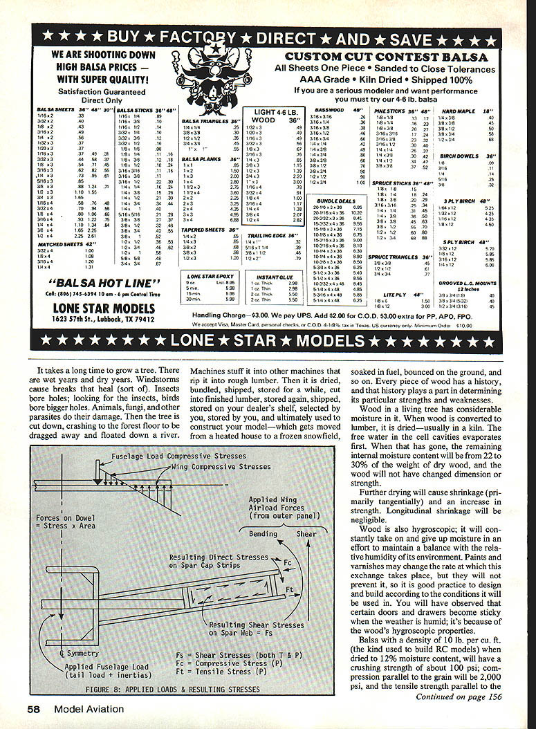
Figure 8 shows where the various stresses may be found on a typical wing joint. Next time we'll break some wood on such a joint.
Remember: There is no such thing as an average piece of wood.
Figure 8 — Applied loads & resulting stresses
- Fuselage load — Compressive stresses
- Wing — Compressive stresses
- Forces on dowel = Stress × Area
- Applied wing airload forces (from outer panel):
- Bending
- Shear
- Resulting direct stresses on spar cap strips
- Resulting shear stresses on spar web = Fs
- Q symmetry
- Applied fuselage load (tail load + inertias)
- Fs = Shear stresses (both T & P)
- Fc = Compressive stress (P)
- Ft = Tensile stress (P)
Structures / Myers — Continued from page 58
George M. Myers 70 Froehlich Farm Rd. Hicksville, NY 11801
Transcribed from original scans by AI. Minor OCR errors may remain.

