
Simplex 300
THE SIMPLEX 300 came into being, at least on my drafting board, in 1965. The design is not solely mine. There have been similar designs before, and certainly a lot since. Some later ones include Mel Schmidt's Shocer; Dennis Bronco's and Sal Taibi's Orbiteer; Dave Rounsville's FAI Excelsior; and a dead ringer, Mike Hallum's Star Seeker. The latest is Jim Clem, the Country Boy.
Thanks to Jim, I won't have to work so hard on writing my flying instructions. There was a time when I would get a little upset every time I saw my model with another name on it, but now I can only say thanks to all who helped to prove that this type of design is a good one. After all, I'd hate to find out after 12 years of playing with the darn thing that it didn't fly.
The Simplex 300 was my effort to design a clean, simple, and quick-to-build consistent model. The rules at the time it was built were: three 5-minute flights, then 6, 7, and so on. The plane has been good up to 30 minutes a number of times (until the pilot goofed). With the Category I rules as they are now, the model can do it on an 8-second engine run, but the air has to be there. I feel that it's still a very competitive Category II model.
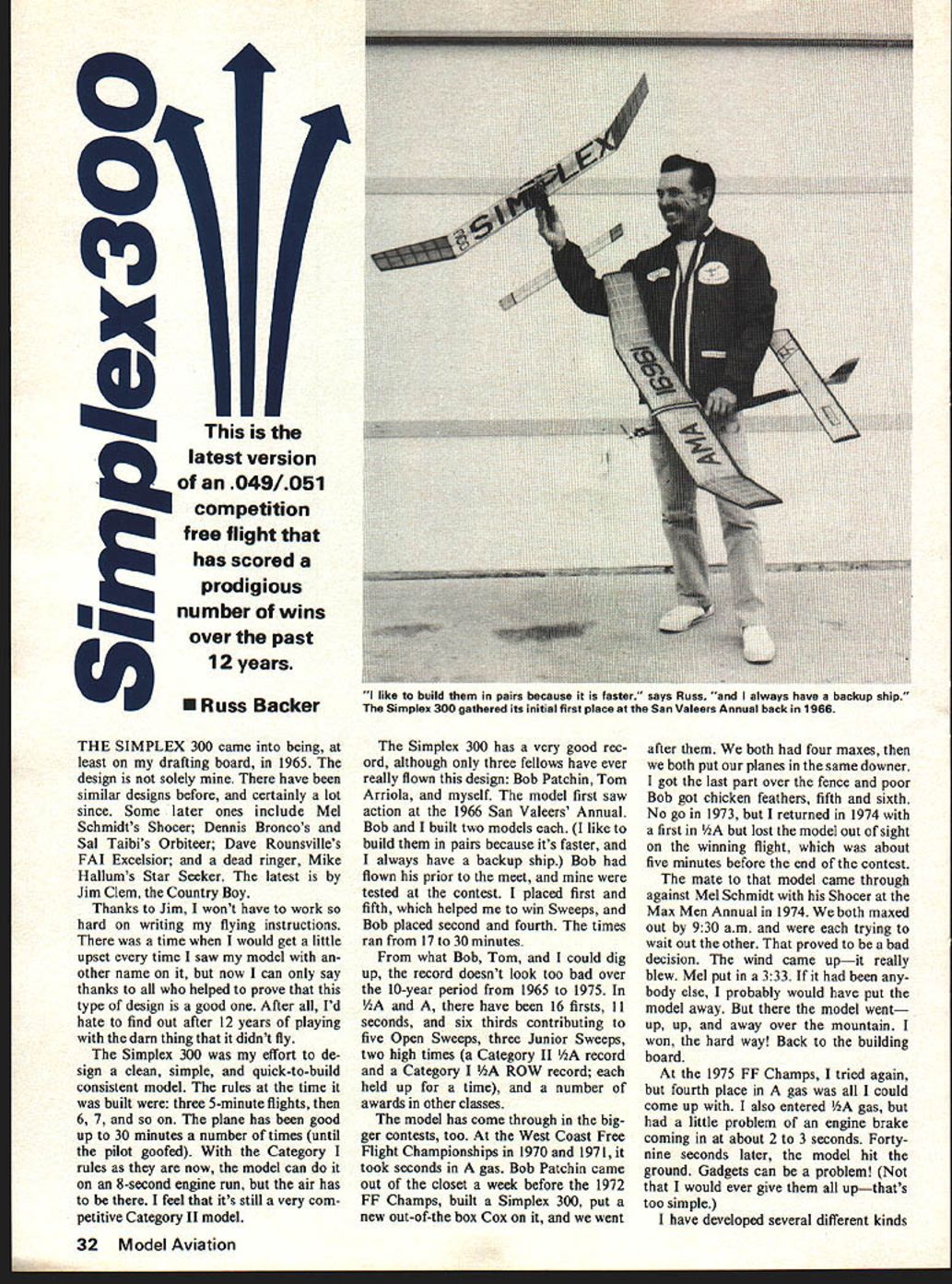
The Simplex 300 has a very good record, although only three fellows have ever really flown this design: Bob Patchin, Tom Arriola, and myself. The model first saw action at the 1966 San Valeers' Annual. Bob and I built two models each. (I like to build them in pairs because it's faster, and I always have a backup ship.) Bob had flown his prior to the meet, and mine were tested at the contest. I placed first and fifth, which helped me to win Sweeps, and Bob placed second and fourth. The times ran from 17 to 30 minutes.
From what Bob, Tom, and I could dig up, the record doesn't look too bad over the 10-year period from 1965 to 1975. In 1/2A and A, there have been 16 firsts, 11 seconds, six thirds contributing to five Open Sweeps, three Junior Sweeps, and two high times (a Category II 1/2A record and a Category I 1/2A ROW record; each held up for a time), and a number of awards in other classes.
The model has come through in the bigger contests, too. At the West Coast Free Flight Championships in 1970 and 1971, it took seconds in A gas. Bob Patchin came out of the closet a week before the 1972 FF Champs, built a Simplex 300, put a new out-of-the-box Cox on it, and we went after them. We both had four maxes, then we both put our planes in the same downer. I got the last part over the fence and got chicken feathers; fifth and sixth. No go in 1973, but I returned in 1974 with a first in 1/2A but lost the model out of sight on the winning flight, which was about five minutes before the end of the contest.
The mate to that model came through against Mel Schmidt with his Shocer at the Max Men Annual in 1974. We both maxed out by 9:30 a.m. and were each trying to wait out the other. That proved to be a bad decision. The wind came up—it really blew. Mel put in a 3:33. If it had been any slower, I probably would have put the model away. But the model went up, up, and away over the mountain. It won, the hard way! Back to the building board.
At the 1975 FF Champs, I tried again, but fourth place in A gas was all I could come up with. I also entered 1/2A gas, but had a little problem of an engine brake coming in at about 2 to 3 seconds. Forty-nine seconds later the model hit the ground. Gadgets can be a problem! (Not that I would ever give them all up—that's too simple.)
I have developed several different kinds I can’t reliably extract the article text from this page as provided — the narrative is printed very small, mostly overlapped by the full-size plans, and the scan resolution/contrast is too low to read the continuous text. To continue cleanly from the prior page and produce an accurate, corrected transcription I need a clearer image.
Please provide one of the following (best to include both):
- A higher-resolution scan of this page (preferably 300–600 dpi). If you can supply a 2000–3000 pixel long side image that also works.
- Or a cropped, high-resolution close-up of the text column(s) (not the diagrams) rotated upright so the text reads normally. Crop to include the entire column margins and any numbered notes or boxed text so nothing is cut off.
- If you only have a phone, take a photo in good light, hold the camera steady and parallel to the page, and send a close crop of the text area at the highest resolution available.
If you’d like, you can also:
- Send the adjacent pages (page 1 or 3) if they include the text continuation.
- Tell me which specific portion you want first (e.g., the paragraph after “I have developed several different kinds…” or the numbered builder’s notes near the plans) and I’ll prioritize that area.
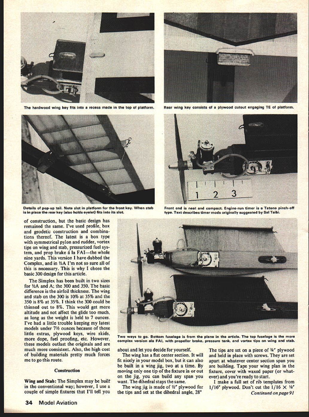
I can then extract and correct the PRIMARY ARTICLE text exactly as requested. of construction, but the basic design has remained the same. I've used profile, box and geodetic construction and combinations thereof. The latest is a box type with symmetrical pylon and rudder, vortex tips on wing and stab, pressurized fuel system, and prop brake à la FAI—the whole nine yards. This version I have dubbed the Complex, and in ½A I'm not so sure all of this is necessary. This is why I chose the basic 300 design for this article.
The Simplex has been built in two sizes for ½A and A: the 300 and 350. The basic difference is the airfoil thickness. The wing and stab on the 300 is 10% at 35% and the 350 is 8% at 35%. I think the 300 could be thinned out to 8%. This would get more altitude and not affect the glide too much, as long as the weight is held to 7 ounces. I've had a little trouble keeping my latest models under 7½ ounces because of those little extras, plywood keys, wire skids, more dope, fuel proofing, etc. However, these models outlast the originals and are much more consistent. Also, the high cost of building materials pretty much forces me to go this route.
Construction
Wing and Stab: The Simplex may be built in the conventional way; however, I use a couple of simple fixtures that I'll tell you about and let you decide for yourself.
The wing has a flat center section. It will fit nicely in your model box, but it can also be built in a wing jig, two at a time. By moving only one tip of the fixture in or out on the jig, you can build any span you want. The dihedral stays the same.
The wing jig is made of 1/2" plywood for the tips and set at the dihedral angle, 28°.
The tips are set on a piece of 3/4" plywood and held in place with screws. They are set apart at whatever center section span you are building. Tape your wing plan in the fixture, cover with waxed paper (or whatever) and you're ready to start.
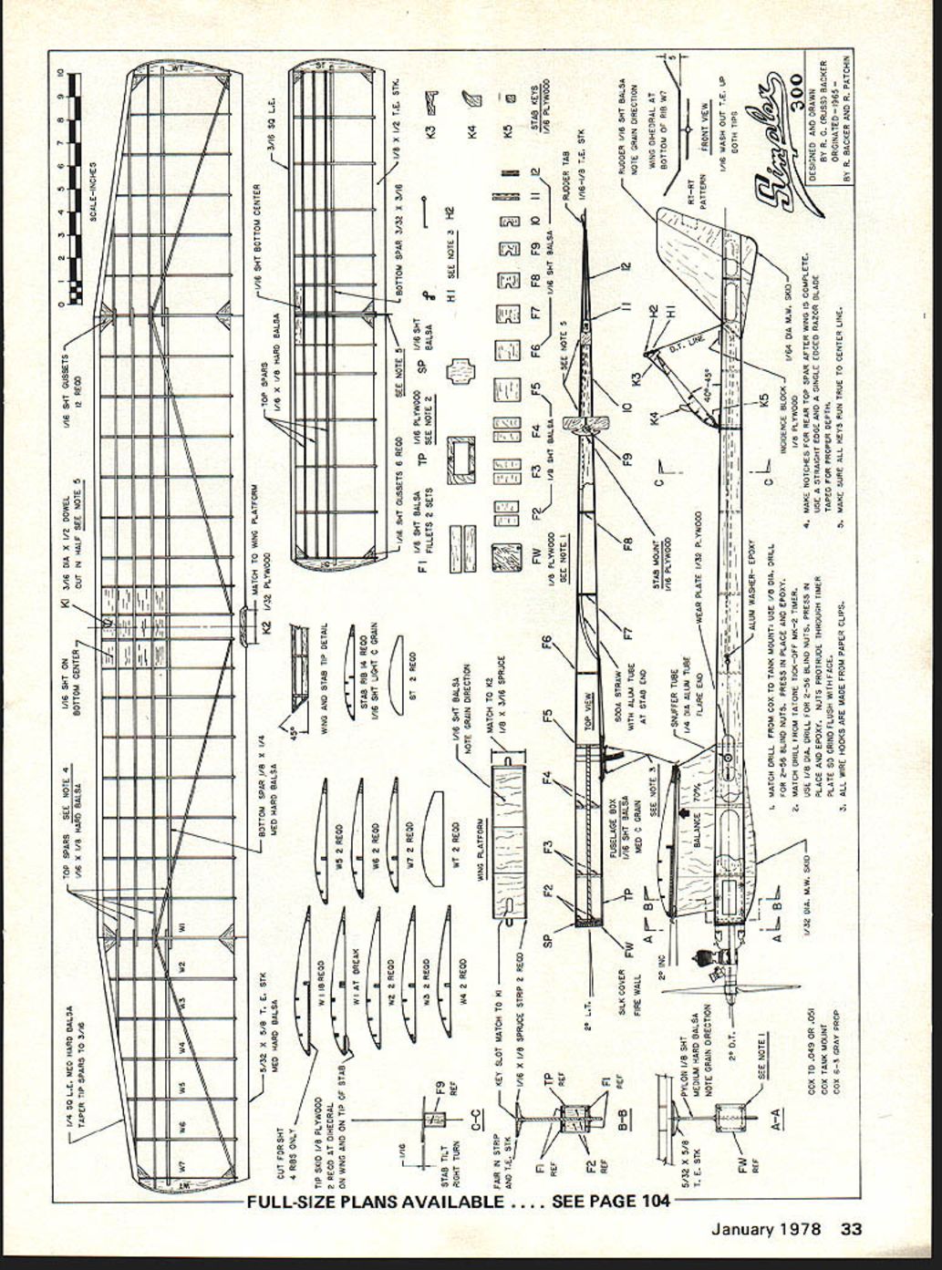
I make a full set of rib templates from 1/16" plywood. Don't cut the 1/16" x 1/8" ... diagonal spar notch. This notch is put in after all other construction is complete. Use a straightedge and a single-edge razor blade. Glue a small stick to the razor blade to set the depth of the cut, then cut the notches. Pick good straight-grain, medium-hard balsa for the center section spars, lighter wood for the tips. The wing can be completed except for the rear diagonal spar. This is put in after the wing is dry. Raise the trailing edge at the tips 1/16", block it, and glue the spars in place. This will give you the washout you need. Everything else is flat. No warps, please.
Because the stabilizer is flat, it can be completed on the plan. The main thing is to keep it light.
Fuselage: The first thing I do is to glue the material for the pylon, using a medium-hard 1/8" balsa sheet. For the rudder, I use 1/16" sheet C-grain. I still use the old model lacquer cement made by Fullers. It works well with nitrates and sands well, but it's getting hard to find. You can also use Tite Bond, Ambroid, or whatever.
While the pylon and rudder are drying, cut out the firewall (FW) and timer plate (TP). Do these together so you can drill all the holes simultaneously. Locate the holes to be drilled using the tank and timer. Use a 1/8" diameter drill for the 2-56 blind nuts. Be sure to check the nuts for threads before you press them in place. (Don't laugh—I've found some without threads.) Before applying the epoxy to them, run the screws in so that they're flush with the back of the blind nut; this keeps the epoxy off the threads. The blind nuts on the timer plate will protrude through, so you'll have to grind them flush with the face.
Next, cut out the sides. I've found that if you're careful, you can cut the sides, top and bottom out of a 1/16" x 4" x 36" sheet of medium C-grain balsa. I use an aluminum straightedge.
Cut off the nose of the left side where it overlaps formers (F3) and butt glue timer plate (TP). Make sure that the right side is up, and by all means, check downthrust angles (2° per plan). A template made from 1/32" plywood may be beneficial. Do the same for left thrust.
Make a tracing or use carbon paper to transfer the outlines for the pylon and rudder, which should be dry by now. Sand them with 220 wet/dry sandpaper. Now you're ready to start the assembly. I use a simple holding and alignment fixture made from a piece of straight-cut pine, 3/4" x 2" x 32". I draw a center line on the 2-in. face. Then I make a 1/16-in. wide saw cut in one end and a 1/16-in. wide cut in the other, using the top view of the fuselage plan as a reference for the depths. You may draw the top view on the fixture, or do as I did and cut it from the plan and glue it to the fixture with contact cement.
Take the pylon and draw a line parallel with the bottom of the fuselage side and slide the pylon in the 5/8-in. slot. Flush the line to the top surface of the fixture and make sure that the hinge angle of the pylon is a 2° incidence. Use a small C-clamp to hold the pylon in place. Do the same with the rudder. Cut out F2 through F5. Align them over the fixture, and glue to the pylon. Be sure to check the left-thrust angle at this time—2°. By the way, if you tend to be a little wild with glue, you may want to wax the surface of your holding fixture.
When the sides are dry, set them in place. Don't glue at the rudder. Use a clamp-style clothespin to hold sides together. Glue at rudder only after F6 through F9 are in place, while checking the alignment of the pylon and rudder with a piece of monofilament line run around them, front to back. Then put in fillets F1. While drying, cut a slot in the top sheet for the pylon and rudder and glue in place. I use a flat weight on top of the fuselage while drying (some pins are necessary in this operation too). When dry, remove from fixture and install soda straws and aluminum tube for the de-thermalizer line. Be sure that all overlaps go in one direction or you'll never get the line pulled through. The line will hang up on the smallest lip. Cut slots in the bottom sheet for the skid and rudder, and glue the bottom on. Put the fuselage together. Back on fixture; weight and pin.
After it's dry, remove the fuselage from the fixture and install the spacer (SP) and the firewall (FW). Recheck down-thrust and left-thrust angles. I use 5-minute epoxy for this job. While this is drying, I cut out the keys, stab mount, and wing platform parts. When you install keys, use a straightedge laid against the pylon and rudder for reference. Do not tilt stab mount more than 1/16" for a right turn. Use 5-minute epoxy for keys. When you install the wing platform, keep it square and straight. Sand out most of the airplane prior to installing keys, stab mount, skid wires, etc.
The entire ship is now ready for final sanding. Silk the firewall and cover with Japanese tissue. Water shrink, then brush on three or four coats of 50/50 nitrate dope. To fuel-proof, put a coat of clear epoxy on the fuselage. On the wing and stab, I use an airbrush and spray two coats of butyrate dope over the nitrate. However, you may wish to use clear epoxy on the whole plane. If you plan to use tissue trim, numbers, etc., cut them out and put them on after the first coat of nitrate.
Timer Modifications
I found that, for a pinch-off timer, the new camera type moves quite slowly. I modify it by removing five to six teeth from the main timer gear so it will snap off about 1/4 in. and pinch off the fuel line. The gear teeth can be removed with a Dremel tool with a 1/16"-diameter cutter; a small pattern file will also work and is probably a little safer. I also put a piece of plastic fuel line as a bumper on the pinch-off arm to prevent cutting the fuel line. I check this quite often. I also use a piece of material cut from a Dr. Scholl's foot pad behind the timer face to insulate the timer from engine vibration (this idea is by courtesy of Sal Taibi).
Testing
Before flying, check the airplane carefully. (Again, no warps, please.) You want 2° down-thrust, 2° left-thrust, 2° incidence in the wing, 0° in the stab, 3/64-in. right stab tilt—that's right side up looking from the rear—1/16-in. washout in the trailing edge of both wing tips, and by all means, 70% C.G.
Pick a calm morning and hand-glide the plane. If everything is as specified, it will have a long, flat, right glide (within a paper shim or two). Before you make your first power flight, double check your timer or proper shutoff. And every time you put in a fuse, don't overlap the rubberband so much that you pinch the fire out. Always check the stab key to see that it's down. If you don't, you'll most likely be picking the model from your back side. Enough said?
I test flew the model I built for this article after it had aged about three months. Not that I like to take that long, but a thing called work keeps getting in the way of my toys. The test went as follows. First flight: prop on forwards, engine running full for 4 seconds, launched at about a 75° angle, slightly to the right of wind. It did half a turn, rolled out, and showed a slightly right tight turn in the glide. Second flight: 7 seconds, full power—no change; just went higher. Third flight: 10 seconds, full power, and I removed about a 1/64 in. of the built-in right turn; model did about one full turn with a nice transition.
I didn't have to use any rudder tab with this model. (I have had to use some on other models, especially when doing VTO.) I use a little more left-thrust with a little right tab and the model goes straight up without falling off on the right wing. As speed builds up, the tab takes effect and the model rolls right.
After the three initial test flights, which were completed by 9:00 a.m., I decided to run a series of flights since the day at Lake Elsinore looked like it was going to be a good one. The motor runs were 9 to 10 seconds using a Cox .049 with a 6D-3P Cox grey prop, 40-40 Fox fuel and motor tach about 18,500 rpm. I was able to get many flights because there was very little drift through most of the day.
After a day of testing, I just knew I was ready for our Thermal Thumbers Mini-FAI Contest at Lake Elsinore on March 6, 1977. The contest was flown in five rounds, 10-second engine runs, 3-minute maxes. At the end of five rounds, I was maxed out. We went into a two-man fly-off, and guess what? Old R.G. short-fused himself. Not a thing wrong with the model—just "pilot" error.
Try a Simplex. I think you'll like it.
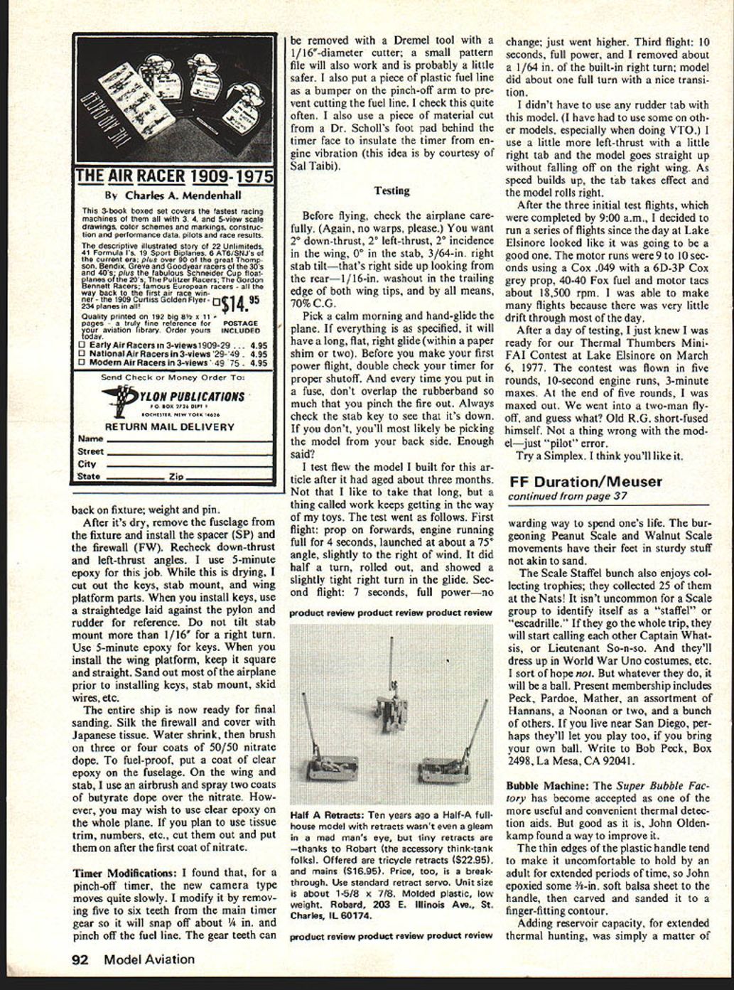
Transcribed from original scans by AI. Minor OCR errors may remain.

