
Sir Rodney
Design by Jim O'Reilly Text and photos by Larry Kruse
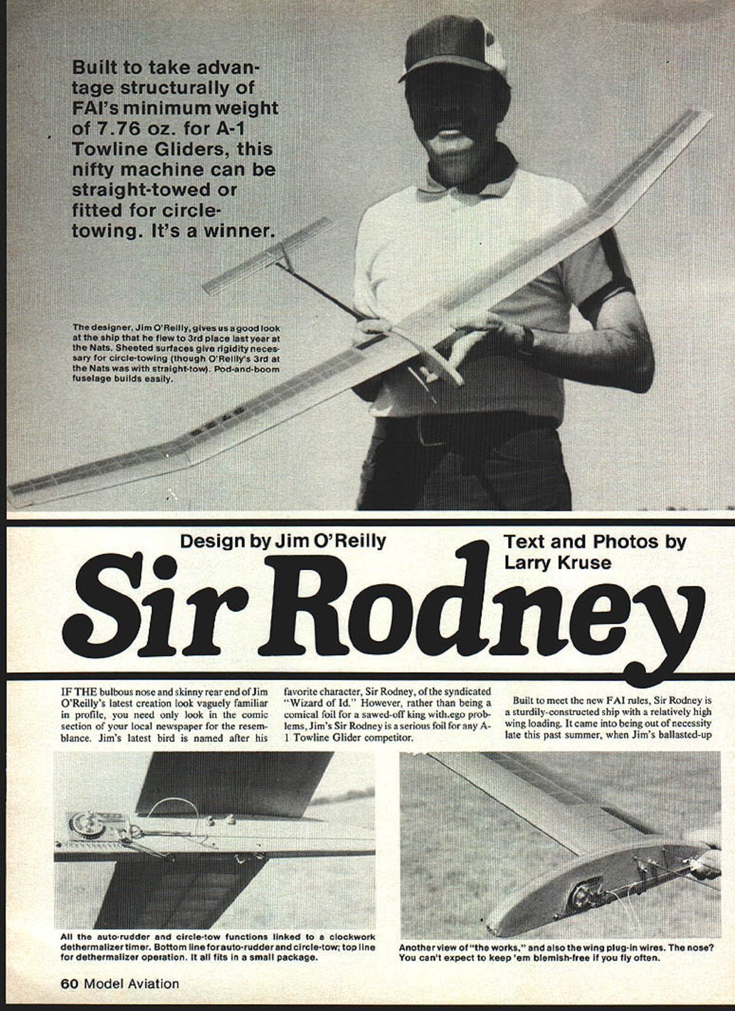
If the bulbous nose and skinny rear end of Jim O'Reilly's latest creation look vaguely familiar in profile, you need only look in the comic section of your local newspaper for the resemblance. Jim's latest bird is named after his favorite character, Sir Rodney, of the syndicated "Wizard of Id." However, rather than being a comical foil for a sawed-off king with ego problems, Jim's Sir Rodney is a serious foil for any A-1 Towline Glider competitor.
Built to meet the new FAI rules, Sir Rodney is a sturdily constructed ship with a relatively high wing loading. It came into being out of necessity late this past summer, when Jim's ballasted-up prototype Sir Rodney was completed about a week before the Nats and test-flown with a circle-tow hook. Due to windy weather Jim could not perfect circle-tow technique in the time available. Instead, he opted to fly Sir Rodney with a conventional tow-hook setup and took third place at Dayton. Since that time, Hatschek's circle-tow hook has been installed with good success, although there has been no contest experience in this mode.
Construction notes
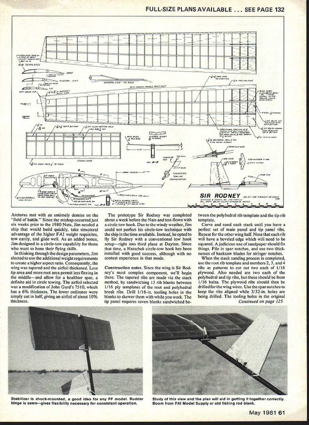
Since the wing is Sir Rodney's most complex component, we'll begin there. The tapered ribs are made via the stack method, by sandwiching 15 rib blanks between 1/16-in. plywood templates of the root and polyhedral-break ribs. Drill 1/16-in. tooling holes in the blanks to skewer them while you work. The tip panel requires seven blanks sandwiched between the polyhedral rib template and the tip rib template.
Carve and sand each stack until you have a perfect set of main-panel and tip-panel ribs. Repeat for the other wing half. Note that each rib will have a beveled edge which will need to be squared; a judicious use of sandpaper should fix things. File in spar notches, and use two thicknesses of hacksaw blade for stringer notches.
When the stack-sanding process is completed, use the root rib template and ribs Nos. 2, 3, and 4 as patterns to cut out two each of 1/16-in. plywood. Also needed are two each of the polyhedral and tip ribs, but these should be of 1/16-in. balsa. The plywood ribs should then be drilled for the wing wires. Use the spar notches to keep the ribs aligned while 3/32-in. holes are being drilled. The tooling holes in the original ribs can be used as a template.
Pre-cut the leading-edge (LE) sheeting to exact length and back-edge contour. Leave some surplus in front. Pin the trailing edge (TE) to the plan, shimming up the front edge by 1/32 in. A 1/16-in. shim is also needed full-length under the front lower spar; a piece of 1/64 x 3/16 in. works well. Pin the lower LE sheet and lower spar into position, and then drop the ribs down over the front lower spar. Trim the aft portions of the ribs, if necessary, and then Hot Stuff or Jet them into place. Work from the outside of each panel toward the middle. Glue all ribs into place, and then install the LE. Take care that the panels match at the polyhedral break.
Remove the panels from the board, and cut the lower LE sheeting surplus down to 1/16 in. or less. Install the lower rear spar, and then re-pin the panels onto the plan, omitting the previous installation shims. Re-shim the tip panels for the needed washout, and then install the top spars and top LE sheeting. Be aware that once the top sheeting is glued in place, this locks out (or in) all warps that are present when it's installed. You might want to double-check the shimmied-in tip washout just to make sure.
The top sheeting can best be installed by punching a pinhole through to the sheeting, and applying Hot Stuff or Jet right through to the underlying ribs. Work from the middle of the panel outward, alternating left and right bays as you go. When sheeting is attached to all ribs, tack-glue it to the LE in the same manner, punching through the sheet from the middle, and working toward both ends.
Once tack-gluing is completed, un-pin all panels, and continue the gluing process. Dihhedral joints, vertical-grain shear webs, and 3/32-in. wing-wire tubes will complete the wing. The turbulators shown on the plan are doped in place after the wing is covered.
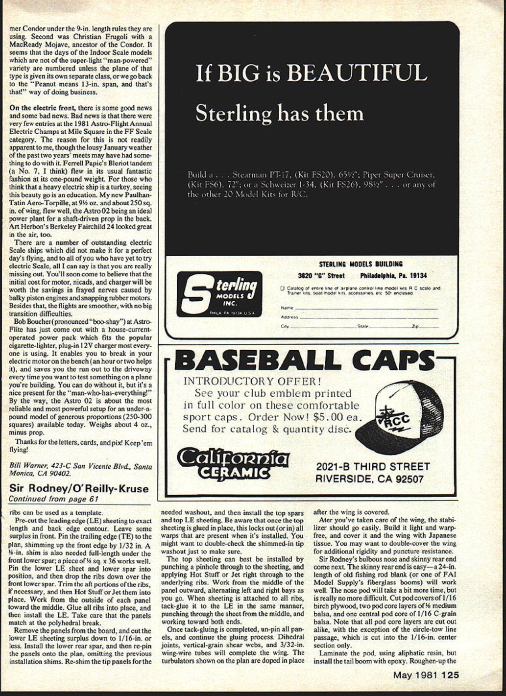
After you've taken care of the wing, the stabilizer should go easily. Build it light and warp-free, and cover it and the wing with Japanese tissue. You may want to double-cover the wing for additional rigidity and puncture resistance.
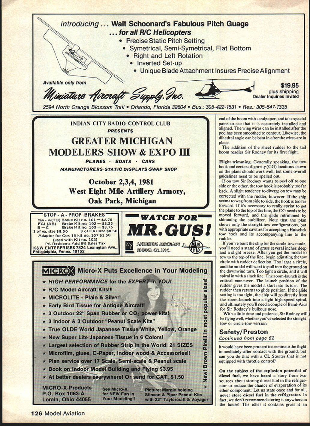
Sir Rodney's bulbous nose and skinny rear end come next. The skinny rear end is easy—a 24-in. length of old fishing rod blank (or one of FAI Model Supply's fiberglass booms) will work well. The nose pod will take a bit more time, but is really no more difficult.
Pod construction materials:
- Two pod covers of 1/16-in. birch plywood
- Two pod core layers of 1/8-in. medium balsa
- One central pod core of 1/16-in. C-grain balsa
Note that all pod core layers are cut out alike, with the exception of the circle-tow line passage, which is cut into the 1/16-in. center section only.
Laminate the pod using aliphatic resin, but install the tail boom with epoxy. Roughen up the end of the boom with sandpaper, and take special pains to see that it is accurately installed and aligned. The wing wires can be installed after the pod has been smoothed to contour. Likewise, the dihedral angle can be bent in after the wires are in place.
The addition of the sheet rudder to the tail boom readies Sir Rodney for its first flight.
Flight trimming
Generally speaking, the tow-hook and center-of-gravity (CG) locations shown on the plans should work well, but some overall guidelines need to be spelled out.
- If on the tow Sir Rodney wants to peel off to one side or the other, the tow hook is probably too far back. A slight tendency to diverge on tow may be corrected with the rudder, however.
- If the ship seems to wag from side to side, the hook is too far forward.
- If it's necessary to really sprint to get the plane to the top of the line, the CG needs to be moved forward, and the glide retrimmed by shimming the stabilizer.
Note that the plan shows only the straight-tow configurations, but with appropriate cavities for accepting a Hatschek tow hook and its accompanying line to the rudder.
If you've built the ship for the circle-tow mode, you'll need a stand of grass several inches deep and a slight breeze. After you get the model to tow to the top of the line, begin adjusting the tow circle with rudder deflection. Too large a circle, and the model will want to pull into the ground on the downwind turn. Too tight a circle, and it will spiral in with a slack line.
The zoom-launch is the critical maneuver. The launch position of the rudder gives the model a start into its turn. The rudder then returns to glide position. If the glide setting is too tight, the ship will go directly from the zoom-launch into a tight high-speed spiral, and ultimately you'll need a couple of Band-Aids for Sir Rodney's bulbous nose.
With a little time and patience, Sir Rodney will be flying well, whether you've selected the straight-tow or circle-tow version.
Transcribed from original scans by AI. Minor OCR errors may remain.

