

Skis for Snow or Grass
If you've been wondering how to keep flying with snow on the ground, here's the answer: build a set of skis. These plywood skis are easy and fast to make, add very little weight to your airplane, and also work well on grass. Because skis impart a degree of stability that wheels do not, you may find they reduce ground-looping on takeoff and landing. These skis use a "knee-action" positioning system closer to full-scale than the torque-rod system.
This article describes procedures for making one ski. Double all parts if you are making a main-gear set only. If you are making a nose-gear ski, length and width measurements will have to be modified. Suggested full-size templates for all parts are included.
Materials and typical sizes
- Main-gear ski (for .40–.60-size ship): about 2-1/2 in. wide by 12 in. long.
- Nose-gear ski (trike-gear ship): about 7 in. long by 1-1/2 in. wide.
- Main construction plywood: 1/8-in. birch model aircraft plywood (not Lite Ply or door covering).
- Keel: 1/16-in. plywood.
- Spines, doublers: 1/8-in. plywood. Gussets: 1/8-in. sq. balsa or spruce (soft spruce preferred).
- Bolts, tubing, brass bushings and axle hardware as required.
Construction and molding the ski blank
- Cut the ski blank from 1/8-in. birch plywood. Round or point the nose as desired, but keep straight sides and sharp bottom edges for good tracking.
- Make a mold press from an 18-in. piece of 2 x 4:
- Draw two parallel lines lengthwise 3/4 in. from the top and bottom edges.
- Trace a 4-in. radius arc from the lower line to the upper line so they intersect about 3 in. from one end.
- Cut along the line with a band saw so you separate the two mold halves, leaving a slightly exaggerated ski profile.
- Insert temporary 1/8-in. scrap plywood spacers along the cut line to represent the ski thickness. Clamp the two mold pieces back together.
- Drill a loose 3/8-in. hole edge-to-edge about 1 in. forward of the tip of the arc (front stop). From the front end of the arc, drill another 3/8-in. hole the exact length of your ski blank to the rear (rear stop). The 3/8-in. holes give a slightly sloppy fit for the bolts by design.
- Insert a 4-1/4–4-1/2-in.-long, 5/16-in.-diameter carriage bolt, washers and nut in the rear hole and tighten; leave the front bolt available to tighten when the blank is in place.
- To form the ski:
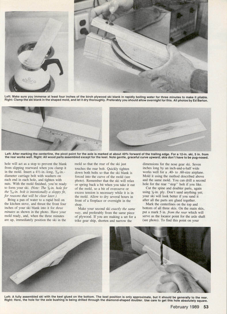
- Bring a pan of water to a rapid boil.
- Submerge the front 4 in. of the ski blank for about 3 minutes to make it pliable.
- Immediately position the blank in the mold so the rear of the blank just touches the rear bolt and quickly tighten both bolts so the blank is forced to the mold curve. Overcurve slightly to allow for spring-back.
- Allow to dry several hours in front of a fireplace or overnight in the shop.
- Make the second ski the same way, preferably from the same sheet of plywood to produce a matched set. If using the mold for both main and nose skis, drill a second rear-stop hole for the shorter blank as needed.
Spines, doublers, keel and glue-up
- Cut spine and doubler parts from 1/8-in. ply. Cut keels from 1/16-in. ply.
- Don’t sand parts yet; the ski will look better if sanded after glue-up.
- Mark the centerlines on the top and bottom of each ski. On main skis, mark a point 5/8 in. from the rear along the centerline to locate the axle shaft.
- Glue the keel to the bottom of the ski (keel position is approximate, generally toward the rear) and clamp.
- Drill the axle-bushing hole through the diamond-shaped doubler; take care to make this hole absolutely square to the ski.
- Using slow-setting epoxy, glue the spines and 1/8-in.-sq. balsa or spruce gussets onto the skis. Do not omit the gussets—they add significant strength for side loads.
- For the nose-gear spine, you may need to sand a slight curve into the bottom edge of the spine to match the ski profile.
- Ensure axle locations remain exactly above their marks and spines remain straight while epoxy sets.
- Epoxy the diamond-shaped doublers to the spines. Round the front and rear ends of the keels with sandpaper and epoxy them along the bottom centerlines of the skis.
Axle bushing and final sanding
- After glue cures, determine axle diameter. Use a drill press to drill a hole 1/16 in. larger than the axle diameter through the exact center of each doubler—keep this hole square to the ski.
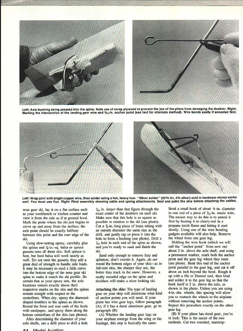
- Cut a 3/8-in.-long piece of brass tubing with an outside diameter matching the drill size; press or gently tap it into the drilled hole to form a bushing.
- Drill a 1/16-in. hole in each end of the spine for cable attachment.
- Sand only to remove fuzz and splinters; do not round the bottom edges of the skis—sharper bottoms track better. Round spine and doubler edges for appearance if desired.
Attaching the skis — anchor points and hardware
The type of landing gear determines anchor-point fabrication.
(A) Wire landing gear legs
- Bend a small hook of about 1/4-in. diameter in one end of a piece of 3/32-in. music wire to form the anchor point:
- Anneal the wire first (heat to cherry red and cool slowly) if bending is difficult.
- Wire-bending tools help.
- Remove the wheel from the axle if possible. Hold the wire hook about 2 in. above the axle shaft, mark the anchor point and gear leg where they meet.
- Bend the end of the anchor point parallel to the gear leg and cut it about 1 in. beyond the bend. Rough in a cup with a file or Dremel, then bind and solder it to the gear leg so the hook is 1/8 in. above the axle—this spacing allows reattaching wheels without removing anchor points (unless using very large wheels).
- Repeat for the other gear leg.
- Use bright copper wire wrap and solder with a heavy iron and appropriate flux. Proper soldering and secure anchoring are essential to prevent loosening under load.
(B) Dural (aluminum) gear
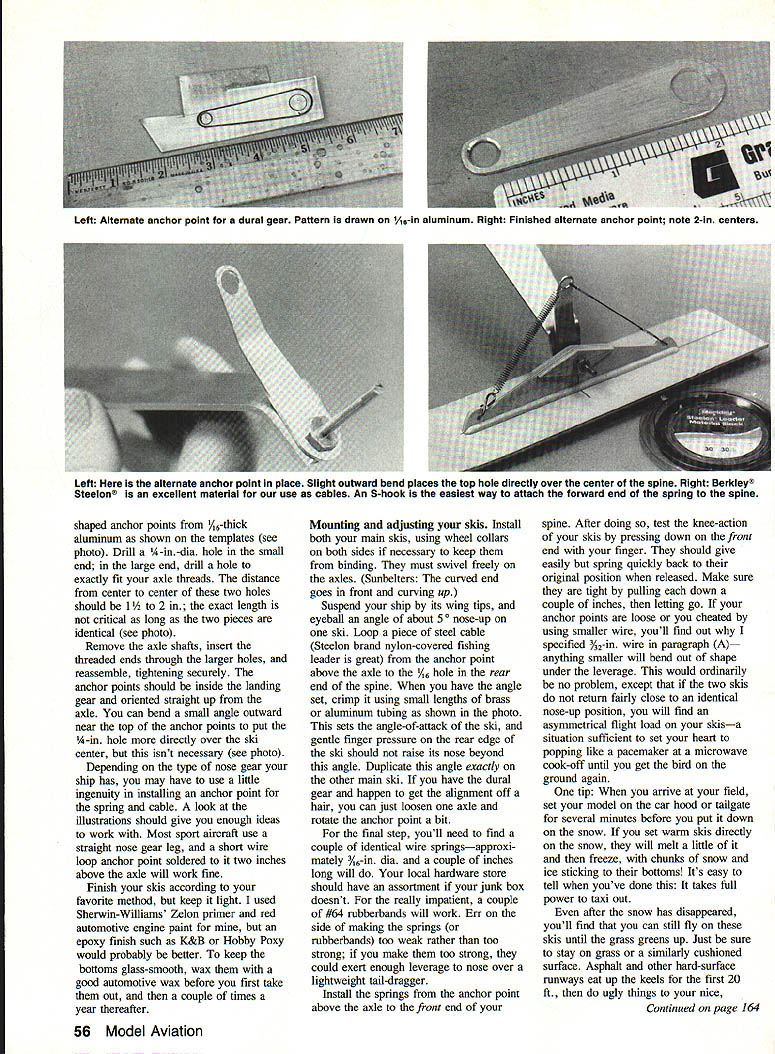
- Cut two rounded, teardrop-shaped plates from 1/16-in. dural and drill them to the proper bolt pattern for your gear legs.
- Bolt the plates to the gear legs and install anchor points for the cable and spring assemblies as required.
Anchor plates (alternative assembly)
- You can make shaped anchor plates from 1/16-in. aluminum. Drill a 1/4-in. hole in the small end and a hole in the large end to fit your axle threads exactly. Center-to-center distance between these holes should be about 1-1/2 to 2 in. (exact length not critical if pieces are identical).
- Remove the axle shafts, insert threaded ends through the large holes and reassemble, tightening securely so anchor points sit inside the landing gear oriented straight up from the axle. A slight outward bend near the top can position the 1/4-in. hole directly over the ski center.
Cables, springs and final attachment
- Attach cable and spring assemblies from the anchor points to the fittings on the skis. Seal and paint skis before attaching cables.
- Install both main skis on the axles. Use wheel collars on both sides if needed to prevent binding. Skis must swivel freely on the axles.
- Note for Sunbelters: the curved end goes in front and curves up.
- Suspend the airplane by the wingtips and eyeball about a 5° nose-up angle on the skis.
- Loop a piece of steel cable from the anchor point above the axle to the 1/16-in. hole at the rear end of each spine. When the correct angle is set, crimp using small lengths of brass or aluminum tubing to fix the angle-of-attack. Duplicate this angle on the other main ski.
- If dural gear alignment is slightly off, you can loosen one axle and rotate the anchor point to adjust.
- Install springs from the anchor point above the axle to the front end of the spine:
- Typical springs: wire springs approx. 3/16-in. dia. and a couple inches long. Hardware-store springs or #64 rubber bands can work.
- Prefer weaker rather than stronger springs—overly strong springs can nose-over a lightweight tail-dragger.
- Test knee-action by pressing down on the ski front end—skis should give easily and spring back quickly. Pull each ski down a couple inches and release to verify return. If anchor points are loose or wire too small, skis may not return equally and asymmetrical load can result.
- Install anchor clamps on the axle mounting so the springs cannot pull off during rough ground action.
Finishing and care
- Finish skis lightly. Epoxy finishes (K&B, Hobby Poxy) are good; automotive primers and paints may be used. To keep bottoms glass-smooth, wax them with a good automotive wax before first use and a couple of times a year thereafter.
- Tip: When you arrive at the field, set your model on the car hood or tailgate for several minutes before placing it on the snow. Warm skis set directly on snow will melt a little and then freeze, causing chunks of snow and ice to stick to the bottoms.
- Even after snow melts, skis work well on grass or other cushioned surfaces. Avoid asphalt or hard surfaces—keels will be damaged quickly.
- For very smooth ski bottoms, waxing is helpful. Some runway surfaces (synthetic mesh, dryer-belt material) are softer and permit smooth takeoff performance even with skis.
Mounting and adjustment checklist
- Skis swivel freely on axles and are centered.
- Springs adjusted so skis trail properly and return to neutral.
- Angle-of-attack set to ~5° nose-up and duplicated on both main skis.
- Springs strong enough to return skis but not so stiff as to tip the airplane forward.
- Anchor clamps installed to prevent springs from pulling off.
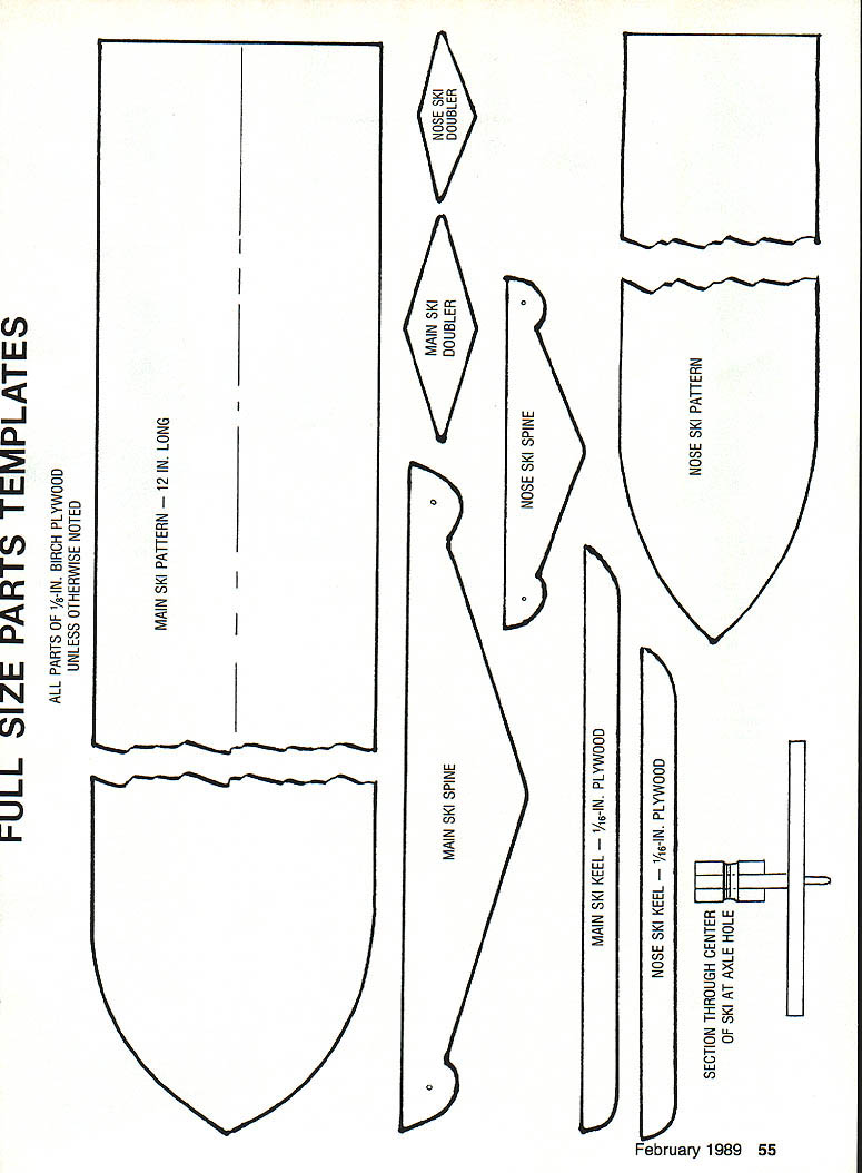
Full-size parts templates
All parts of 1/8-in. birch plywood unless otherwise noted.
- Main ski pattern — 12 in. long
- Main ski spine
- Nose ski spine
- Main ski doubler
- Nose ski doubler
- Nose ski pattern
- Main ski keel — 1/16-in. plywood
- Nose ski keel — 1/16-in. plywood
- Section through center of ski at axle hole
(Templates referenced above should include the drilled-hole locations and outlines for the keels, spines and doublers. Adjust nose-gear templates for trike-gear dimensions as noted.)
About the author: Graham H. Hicks
Transcribed from original scans by AI. Minor OCR errors may remain.

