
Sky Baby
Frank H. Scott
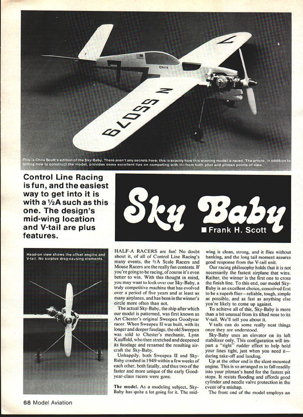
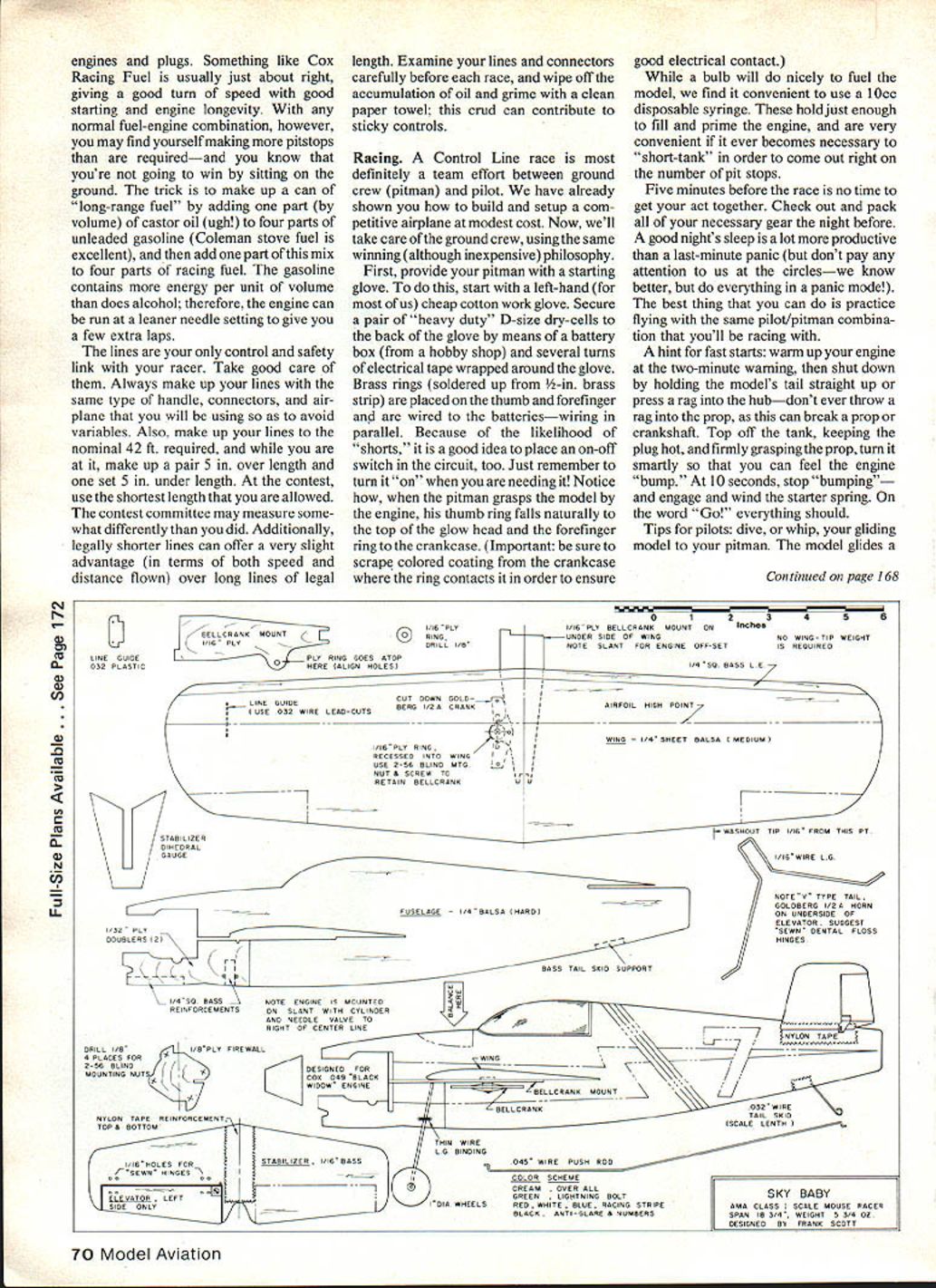
Control-line racing is great fun, and the easiest way to get into it is with a 1/2A such as this one. The Sky-Baby model is a truly competitive machine that evolved over about five years and has often finished in the winner’s circle. It is patterned after Art Chester’s original Sweepea Goodyear racer (later modified and renamed Sky-Baby by Lynn Kauffold). As a modeling subject it has a lot going for it: a mid-wing layout, clean strong structure, a long tail moment for good V-tail response, and simple, tough construction.
Notable features
- Mid-wing location for clean, strong mounting and stable flight without excessive banking.
- V-tail with elevator only on the left stabilizer to impart a slight right-rudder effect (helps hold line tension during takeoff and landing).
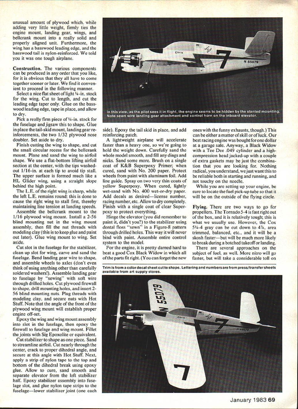
- Slant-mounted (tilted) engine for fast pit stops, resistance to flooding, and protection of cylinder and needle valve in mishaps.
- Substantial plywood at the front end to tie engine mount, landing gear, wing, and bellcrank into a solid, aligned unit.
- Basswood leading edge on the wing and nylon-reinforced basswood tail for durability.
Construction
The components can be made in any order, but the following sequence is convenient.
- Wing
- Select a flat sheet of light 1/4-in. stock for the wing. Cut to length and cut the leading-edge taper.
- Glue on the basswood leading edge, tape in place, and allow to dry.
- Finish cutting the wing to shape and cut the small circular recess for the bellcrank mount.
- Plane and sand the wing to an airfoil shape. Use a flat-bottom lifting airfoil at the center and wash out each tip 1/16 in. to avoid tip stall. Form the upper surface with a straight slope behind the high point (much like an HL glider wing).
- Make the right wing leading edge sharp and keep the left leading edge round — this causes the right wing to stall first and helps maintain line tension at landing speeds.
- Assemble the bellcrank mount to the 1/16-in. plywood wing mount. Install a 2-56 blind mounting nut in the wing-mount assembly and fill the nut threads with modeling clay to keep glue and paint out later. Glue the wing mount to the wing. Set aside.
- Fuselage and firewall
- Pick a firm piece of 3/4-in. stock for the fuselage and jigsaw to shape.
- Glue in the tail-skid mount, landing-gear reinforcements, and the two 1/32-in. plywood nose doublers. Set aside to dry.
- Cut the slot in the fuselage for the stabilizer and clean up the slot for the wing. Carve and sand the fuselage.
- Cut the plywood firewall to shape, drill mounting holes, and insert 2-56 blind mounting nuts. Plug the threads with modeling clay. Note that the angle of the front of the plywood wing mount establishes proper engine offset.
- Landing gear
- Bend the landing-gear wire to shape and assemble wheels to axles (use carefully soldered washers for reliability).
- Assemble the landing gear to the fuselage by “sewing” with soft wire through drilled holes.
- Assembly of wing and firewall
- Epoxy the wing and wing-mount assembly into the fuselage slot, then epoxy the firewall to the fuselage and wing mount.
- Fillet joints with Sig Epoxolite or equivalent.
- Stabilizer and elevator
- Cut the stabilizer to shape and sand to a streamlined airfoil.
- Cut nearly through the center, crack to the proper dihedral angle, and secure at that angle with Hot Stuff.
- Apply a strip of nylon tape top and bottom over the dihedral break using epoxy glue. Allow to cure, sand smooth, and separate the elevator from the left stabilizer half.
- Epoxy the stabilizer assembly into the fuselage slot, and glue nylon tape strips to the fuselage at the lower stabilizer joint (one each side).
- Epoxy the tail skid in place and add a reinforcing patch.
- Finishing
- Sand the whole model carefully to keep weight down. Fill any dings and nicks, then sand smooth.
- Brush on a single coat of K&B Superpoxy primer; when cured, sand with No. 200 paper.
- Protect wheels from paint with aluminum foil and add the line guide.
- Spray two very thin coats of yellow Superpoxy. When cured, lightly wet-sand with No. 400 wet-or-dry paper.
- Add decals (license number, racing number, etc.) and allow to dry completely.
- Finish with a single coat of clear Superpoxy to protect everything.
- Hinge the elevator (after painting) to the stabilizer using dental floss “sewn” in a figure‑8 pattern through drilled holes so it will not bind with paint.
- Assemble the entire control system to the model.
Engine installation and setup
- The slant-mounted engine is arranged for easy pit access and to resist flooding; the model will accept .049 power (Cox Black Widow recommended).
- It is hard to beat a good Cox Black Widow in which all parts fit right. A Black Widow with a Tee Dee .049 cylinder and a high-compression head stacked with an extra gasket or two can be an excellent, reliable racing powerplant. The goal is reliability in starting and running and a needle that isn’t touchy.
- While setting up the engine, locate the fuel pick-up tube so that it will be on the outside of the flying circle.
Flying
Propellers
- Tornado 5-4: fast out of the box and relatively tough — a common choice.
- Cox 5-4 gray: can be cut down to 4-3, area trimmed and balanced; may be a bit faster but is more likely to break during a botched takeoff or landing.
Fuel and engine care
- More nitro will increase speed but also increases engine wear and heat. Keep the engine rich enough to control combustion temperatures.
- After three flights, when satisfied with engine and trim, sprinkle a little graphite or talc on the control lines and the bellcrank to prevent seizing.
Tips for pitmen
- The model will be traveling quite fast when it touches down. The engine and its mounting form the strongest part of most 1/2As, so a good technique is to field a moving dead-stick airplane by its nose.
- Hold the filled fuel syringe in the left hand (already wired for starting), leaving the right hand free for catching.
Fly smooth and have fun racing.
Materials list
- 1/8 x 3 x 36 in. balsa (hard) — fuselage
- 1/4 x 3 x 36 in. balsa (light) — wing
- 1/16 x 2 x 18 in. basswood — tail
- 1/8 x 3/8 x 36 in. — wing and tail-skid mount
- 1/32 in. plywood — doublers
- 1/16 in. plywood — wing mount
- 1/16 in. plywood — firewall
- .062 in. diameter wire — landing gear
- .045 in. diameter wire — pushrod
- .032 in. diameter wire — tail skid
- .025 in. diameter wire — lead-outs
- 5-minute epoxy glue
- Hot Stuff (CA adhesive)
- Goldberg 1/4A control horn set
- Goldberg nylon reinforcing tape
- 2-56 blind mounting nuts (5)
- 2-56 x 1/8-in. screws (5)
- K&B Superpoxy primer, yellow, and clear
- Cox Black Widow engine (Tee Dee .049 cylinder & optional high-compression head)
- Tornado 5-4 nylon prop (or Cox 5-4 gray trimmed to taste)
Transcribed from original scans by AI. Minor OCR errors may remain.

