
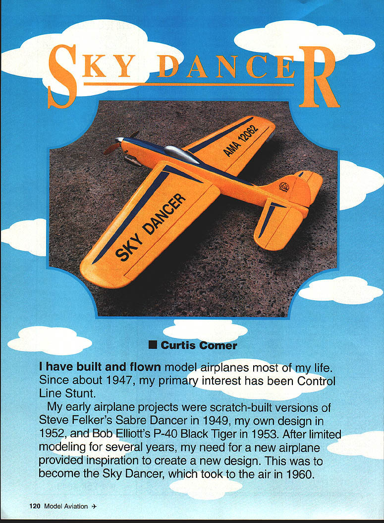
Sky Dancer
Curtis Coiner
I have built and flown model airplanes most of my life. Since about 1947, my primary interest has been control line stunt.
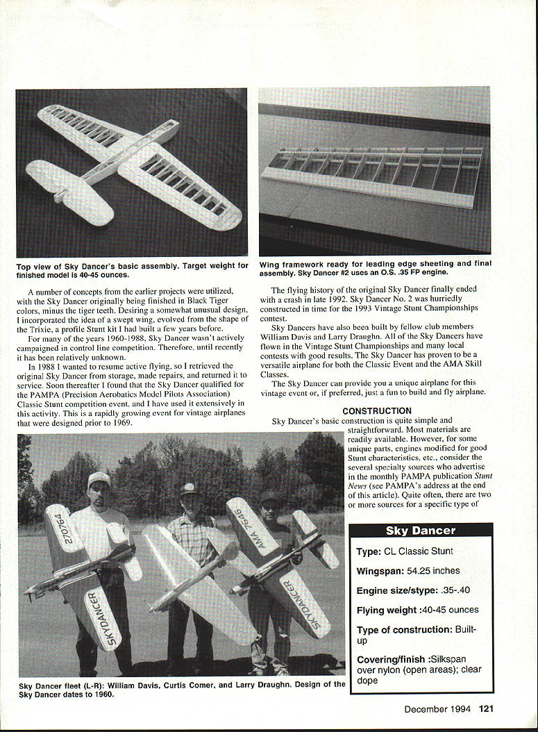
My early airplane projects were scratch-built versions of Steve Felker's Sabre Dancer in 1949, my own design in 1952, and Bob Elliott's P-40 Black Tiger in 1953. After limited modeling for several years, my need for a new airplane provided inspiration to create a new design. This became the Sky Dancer, which first flew in 1960.
A number of concepts from the earlier projects were utilized, with the Sky Dancer originally finished in Black Tiger colors, minus the tiger teeth. Desiring a somewhat unusual design, I incorporated a swept wing evolved from the shape of the Trixie, a profile stunt kit I had built a few years before.
For many years (1960–1988), Sky Dancer wasn't actively campaigned in control line competition and remained relatively unknown. In 1988 I retrieved the original Sky Dancer from storage, made repairs, and returned it to service. Soon thereafter I found that the Sky Dancer qualified for the PAMPA (Precision Aerobatics Model Pilots Association) Classic Stunt competition event, and I used it extensively in that activity. PAMPA's Classic Stunt is a rapidly growing event for vintage airplanes designed prior to 1969.
The flying history of the original Sky Dancer ended with a crash in late 1992. Sky Dancer No. 2 was hurriedly constructed in time for the 1993 Vintage Stunt Championships. Sky Dancers have also been built by fellow club members William Davis and Larry Draughn. All have flown in the Vintage Stunt Championships and many local contests with good results. The Sky Dancer has proven to be a versatile airplane for both the Classic event and the AMA skill classes.
The Sky Dancer can provide a unique airplane for vintage events or, if preferred, just a fun-to-build and fly model.
Specifications
- Type: CL Classic Stunt (P-4)
- Wingspan: 54.25–54.5 inches (listed variations)
- Engine size/type: .35–.40 cu in (Fox .35, O.S. FP .35, O.S. Max .35)
- Flying weight: 40–45 ounces (target)
- Type of construction: Built-up
- Covering/finish: Silkspan over nylon (open areas); clear dope
- Design: Sky Dancer dates from 1960
- Designed by: Curtis Coiner; modified by John Hagan
- Notable builders: William Davis, Curtis Coiner, Larry Draughn
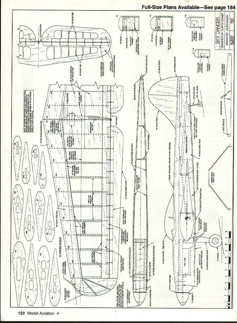
Construction
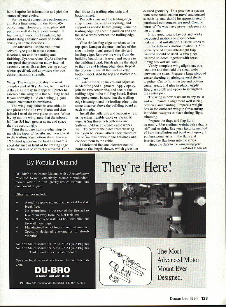
Sky Dancer's basic construction is simple and straightforward. Most materials are readily available, though some unique parts and specially modified engines may require specialty sources. PAMPA's monthly publication Stunt News lists several suppliers (see PAMPA address at the end). There are often multiple sources for the same material.
For competitive performance, aim for a finished weight of 40–45 ounces. The airplane still performs well if slightly overweight. If lightweight wood isn't available, substitute thinner wood of medium density where practical.
Adhesives:
- Use solvent-type glue on external joints where ease of sanding and finishing is desired.
- Use cyanoacrylate (CA) adhesives to speed many internal assembly tasks.
- Use slow-curing epoxy where maximum strength is required.
Wing
The wing is the most complex part but not difficult. I prefer to assemble the wing flat on the building board; a wing jig is normally unnecessary. The wing may be built as one piece or in two pieces and joined. If you use the two-piece method, note that the inboard half has 3/4 inch greater span and space the ribs accordingly.
Construction steps:
- Trim and square the trailing-edge strips to match the taper of the ribs. Glue the trailing-edge bottom sheet in place.
- Place 1/16-inch sheet spacers on the building board a short distance in front of the trailing edge so the ribs will be correctly elevated. Glue the ribs to the trailing-edge strip and bottom sheet.
- Pin both spars and the leading-edge strip in position to align everything; support as needed before gluing.
- Glue the trailing-edge top sheet into position and add shear webs between the spars.
- Glue the leading-edge top sheet to the top spar. Dampen the outer surface of the sheet to help it curl around the ribs and leading edge.
- Remove the wing from the building board, turn it over, and secure it. Finish gluing the sheet to the ribs and leading-edge strip. Repeat to install the leading-edge bottom sheet.
- Add top and bottom rib cap strips.
Joining two wing halves:
- Test-fit the wing halves and adjust for good alignment.
- Apply epoxy, join the two center ribs, and secure the trailing edge to the building board.
- Before the epoxy cures, ensure the trailing edge is straight and the leading edge is the same distance above the building board at each wingtip.
- Apply fiberglass cloth and epoxy to strengthen the center joint.
- Prepare a weight box in the outboard wingtip for securing individual weights during flight trimming.
Controls and hardware:
- Install the bellcrank and leadout wires using either flexible cable or 1/32-inch music wire. A Sig 3-inch bellcrank and Sullivan C-D size flexible cable work well.
- To prevent the cable from wearing a nylon bellcrank, attach short pieces of 1/32- or 3/64-inch music wire to the bellcrank and connect them to the cable.
- I fabricated flap and elevator control horns to the indicated lengths to achieve the desired geometry; 3/32-inch wire control horns have proven adequate.
- Lay out and verify control motions on paper before final installation. I install stops to limit bellcrank motion to about +50°.
- Use an adjustable-length flag pushrod—one approach is a two-piece pushrod soldered together with brass tubing.
Flaps and hinges:
- Prepare the flaps from medium-weight balsa that is stiff and straight. I put basswood strips in the flaps and inserted the flap horn into those strips; bond with epoxy.
- Hinge the flaps to the wing using full-span fabric hinges of .005-inch polyester taffeta for a sealed hinge line.
- Make the initial hinges at the fuselage about 1 inch in, and about 2 inches wide on subsequent hinges.
- Apply masking tape on the trailing edge and on the flaps about 1/2 inch from the hinge line to give a straight edge for installing the hinges with uniform overlap.
- Connect the pushrod to the flap horn and adjust so the bellcrank and flaps are centered, have equal motion, and move freely through full travel.
- Trim the flaps to length, then attach wingtips.
Fuselage
Plan the motor and muffler combination before beginning. The stock nose length is suited to a lightweight system like a Fox .35 or an S. Max .35 with a tongue-type muffler. With a heavier engine (for example, an O.S. FP .35 with stock muffler), shorten the nose at least 1/2 inch or use a Fox 1/2-inch prop-shaft extension to move engine weight rearward.
- Allow room for a fuel tank; a 4-ounce tank is adequate. Use a proven engine that provides a good "stunt run," especially if using a potted engine.
- Assemble the engine crutch with epoxy. Increase the crutch width slightly if needed to accept the engine and fuel tank (most stock fuel tanks are 2 inches wide).
- Position former F-1 to match the engine position. The crutch is spaced so the mounts are 1/8 inch below the top edge of the fuselage sides.
- Drill engine-mount holes to provide approximately 1/8 inch of offset. Add 4-40 blind nuts and test-fit the engine.
- Make the fuselage sides with a little extra nose length and laminate plywood doublers with epoxy. Position the crutch and fuselage sides upside down on the building board, align, and bond with epoxy.
- Prepare formers F-3, F-4, and the rear filler block. Align the fuselage with a jig or templates and glue everything in place. Add diagonal braces between the fuselage sides (top and bottom) for torsional rigidity.
- Use lightweight balsa for the top block. Tack-glue it in place and carve to approximate final shape.
- With the top block temporarily in place, cut the fuselage sides below the wing and carefully align and epoxy the wing into the fuselage. Replace fuselage cutouts and add 1/32-inch plywood doublers over the joints.
- Remove the top block and hollow to approximately 1/8-inch wall thickness. Add bellcrank-shaft top and bottom supports.
- Bolt the landing gear to the mounting plate, position in the fuselage, and secure with epoxy.
- Mount the motor on 1/8-inch aluminum spacers and set for about 1° offset. The engine is semi-enclosed with a fixed thrust line.
Fuel tank mounting:
- A removable and adjustable fuel tank is recommended. One method is a 4-40 bolt through the tank center into a blind nut secured between the engine mounts.
- If building the tank, fabricate the center hole by soldering 5/32-inch brass eyelets in the top and bottom surfaces and soldering a 7/64-inch brass tube within the eyelets to seal and prevent crushing the tank when the mounting screw is tightened.
- The fuselage area below the tank may be left open or covered with a removable hatch.
Empennage
- Make the stabilizer and elevator from light- to medium-weight balsa that is stiff and straight. Cut lightening holes and add ribs as shown in the plans; substitute built-up or solid construction if you prefer closed bays.
- Add the elevator horn and hinges using the same method used for the flaps.
- Cut the fin and rudder from lightweight balsa.
- Prepare the elevator pushrod and trial-fit the stabilizer, elevator, and pushrod into the fuselage. The elevator and flaps should be neutral and have full motion with no binding.
- Align the stabilizer and elevator carefully to the fuselage, wing, and flap-hinge line before final glue.
- Lubricate all metal-to-metal contact points in the control linkage.
Final Assembly
- Verify complete wing alignment and add shear webs between the spars.
- Prepare a large piece of center sheeting (gluing several sheets together if needed), cut to fit the top and bottom center areas, and glue in place.
- Apply fiberglass cloth and epoxy to strengthen the center joint; this resists twist and maintains alignment during covering and painting.
- Glue the top block in place and shape as required.
- Prepare the side-wheel mounting assembly and attach with epoxy. Add fuselage bottom sheeting.
- Prepare the flap and elevator horn assemblies and verify control geometry and travel. I set up the elevator horn and pushrod with almost no built-in looseness; the airplane still tracks well in level flight.
- Glue canopy, nose ring, filler blocks, and shape the cowling. Cut openings for the muffler and needle valve.
- Apply fillet material (for example, Sig Epoxolit) around the wing, stabilizer, fin, and cockpit.
Covering and Finish
Use your preferred covering and finishing method to achieve the desired result. My lightweight dope-based approach:
- Apply a thin coat of clear epoxy paint (such as K&B Superpoxy) to seal wood, glue joints, and fabric hinges. Sand well.
- Apply clear dope.
- Apply Dave Brown Skyloft spun nylon over the open areas for puncture resistance.
- Cover the remainder with lightweight (00) silkspan over the Skyloft where used.
- Proceed with usual dope finishing steps to achieve the final appearance.
Cut a bubble canopy to fit (a Sig 8- or 9-inch canopy works well). Add cockpit detail as desired and epoxy the canopy in place.
Power System
- Original Sky Dancer: Fox .35 with a tongue-type muffler.
- Sky Dancer No. 2: O.S. FP .35 with a modified stock muffler.
- Other examples: O.S. Max .35 with tongue-type mufflers.
I modify the FP .35 to provide the consistent, fairly fast run I prefer. All these power systems have worked well; choose and tune a system that suits you. Used or rebuilt engines are acceptable if new engines are unavailable.
Flying and Trimming
As with many stunt airplanes of 1960 vintage, adjustability is somewhat limited, but significant trimming and tuning are possible. Read widely and expect trimming to be an ongoing process. The following settings are a good starting point:
- Center of gravity (CG): 6-3/16 inches in front of the flap hinge line.
- Rudder offset: 3/8 inch.
- Engine offset: 1°.
- Right thrust: 1 ounce.
- Lines: 62–64 feet.
- Handle spacing: 3/8 inch.
- Prop: Use as low a pitch as possible that still yields the desired lap times (usually about 5-inch pitch or slightly less).
Initial flight checks:
- Verify the wing is level in both upright and inverted flight; tweak the flap horn if necessary to correct any variation.
- Adjust fuel tank height to obtain the same engine speed upright and inverted.
- Experiment with engine settings, glow plugs, fuel, lap speed, sealed hinge lines, trim tabs, and other variables until satisfied with handling.
Over the years the Sky Dancer has been an interesting and enjoyable airplane for me. I hope it proves the same for you.
For more information on Classic Stunt and supplier leads, contact: PAMPA, 327 Pueblo Pass, Anniston, AL 36206.
Transcribed from original scans by AI. Minor OCR errors may remain.

