
Skyvolt
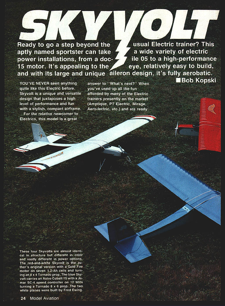
Ready to go a step beyond the usual electric trainer? This aptly named sportster can accept a wide variety of electric power installations, from a .05 to a high-performance .15 motor. It's appealing to the eye, relatively easy to build, and—thanks to its large, unique aileron design—fully aerobatic.
Bob Kopski
You've never seen anything quite like this electric design. Skyvolt is a unique and versatile airplane that juxtaposes strong performance and fun with a stylish, compact airframe.
For the relative newcomer to electrics, this model answers "What's next?" When you've exhausted the fun of many of the electric trainers on the market (Amptique, PT Electric, Mirage, Aero‑lectric, etc.) and are ready for a performance step beyond, Skyvolt may be just what you need. It's also a good choice for the experienced modeler who'd like to try quiet electric power.
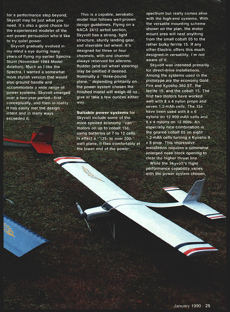
Skyvolt evolved over a two‑year period—first conceptually, then in reality—and was inspired by the Spectra Stunt. It has met the design intent and in many ways exceeded it.
The design follows well‑proven guidelines. Flying on a NACA 2412 airfoil section, Skyvolt has a strong, light structure, sturdy landing gear, and a steerable tailwheel. It's designed for three or four channels, with one channel always reserved for ailerons. Rudder (and tail‑wheel steering) may be omitted if desired. Nominally a "three‑pound plane," the finished model will typically weigh about 48 oz., give or take a few ounces depending on the power system chosen.
Suitable power systems include economy "can" motors up to cobalt .15s, using battery packs of 7 to 12 cells. In effect it's a 125‑ to over 200‑watt airplane: comfortable at the lower end but really alive with high‑end systems. The versatile motor‑mount scheme will accept anything from a small cobalt .05 to a rather bulky ferrite .15.
Recommended installations used in the prototype include:
- Economy Gold Fire and Kyosho 360 ST motors with 8 x 4 nylon props and seven 1.2‑Ah cells.
- Ferrite .15 on 10 x 900‑mAh or 12 x 900‑mAh cells (8 x 6 nylon props or 8 x 4 nylons respectively).
- Geared cobalt .05 on eight 1.2‑Ah cells turning a Kyosho 9 x 8 prop (requires an enlarged nose‑block opening for the higher thrust line).
Whatever power combination you choose, everything works much better with a speed control. Do not build the model without one.
Performance notes:
- Large ailerons permit easy consecutive rolls.
- Inside loops are effortless; outside loops are possible in a light breeze.
- The model takes a definite, directed attitude in moderate winds and handles them easily.
- A slight down stick holds inverted flight; it will climb from inverted into a light breeze.
- Skyvolt stalls, spins, and snaps; it has a wide speed range and controlled landings.
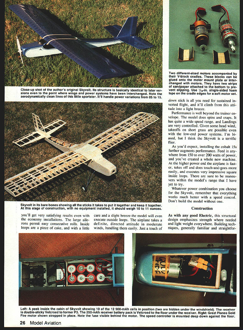
- Higher‑power installations (150–200+ watts) create a noticeably faster, more capable machine—faster acceleration, easier touch‑and‑go, and very impressive square inside loops.
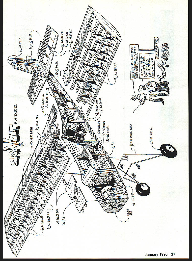
Construction
As with any good electric model, Skyvolt emphasizes strength where needed and light weight everywhere. Building techniques are generally straightforward; a few procedures are specific to Skyvolt.
Tail surfaces
Tail surfaces are simple, quick structures. Select straight, lightweight balsa for edges. Sand rudder and elevator hinge lines and taper the edges as indicated. Use tape hinges (prototype used Scotch catalog #190 clear plastic tape) or conventional hinges as you prefer—if using conventional hinges, sand hinge edges accordingly.
- Position the half‑circle cutout in the rudder to clear the hinge‑pinned elevator joiner piece.
- Pencil guide marks for stabilizer assembly to aid mounting the fin/rudder/stab assembly to the fuselage.
- Mark and drill 1/2‑in. holes for horn mounting screws in the rudder and elevator.
- The completed tail structure should weigh about 3/4 oz. uncovered.
Fuselage
Begin by selecting two pieces of 1/16 x 4 x 36‑in. medium balsa (together about 1.5–2.0 oz.). Join the sheets with double‑stick tape (Scotch #665 or similar) in three or four places and trim one edge straight using a metal straightedge; each straight‑cut edge becomes a fuselage bottom edge.
- Outline the fuselage profile on each side, cut out, and sand; a finished pair typically weighs about 1/4 oz.
- Mark and drill 3/16‑in. wing hold‑down dowel holes using a sharpened brass tube as a drill guide.
- Remove tape residue and lay side sheets over the top‑view plan, straight edge to bottom edge. Mark vertical lines to locate formers and uprights—this simplifies assembly and improves alignment.
- Glue in 1/8‑in. square longerons and verticals, using a scrap spacing guide where formers will be placed.
- Add 1/8‑in. strips and pieces, undrilled 1/8‑in. wing saddle doublers, and 1/8‑in. Lite Ply bottom nose doublers. Sand the structure smooth.
Add reinforcements:
- Drill through wing saddle doublers at dowel locations, using the side sheet holes as guides.
- Add 1/4‑in. square hard balsa pieces in the landing gear area.
- Install 1/8 x 1/4 and 1/8 x 3/8‑in. strips in the hatch area, front triangle fill stock, and light balsa 1/8 x 3/8‑in. side battery guides.
- Mark and cut pushrod exits; block‑sand edges to match.
Cut formers, servo tray, motor mount pieces, and landing gear plate from indicated materials. If your servos differ from the S‑33s shown, modify the servo mounting plate accordingly (only microservos are recommended).
Box up the fuselage:
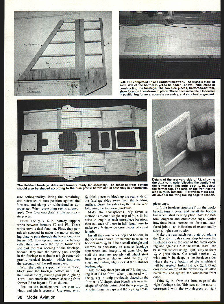
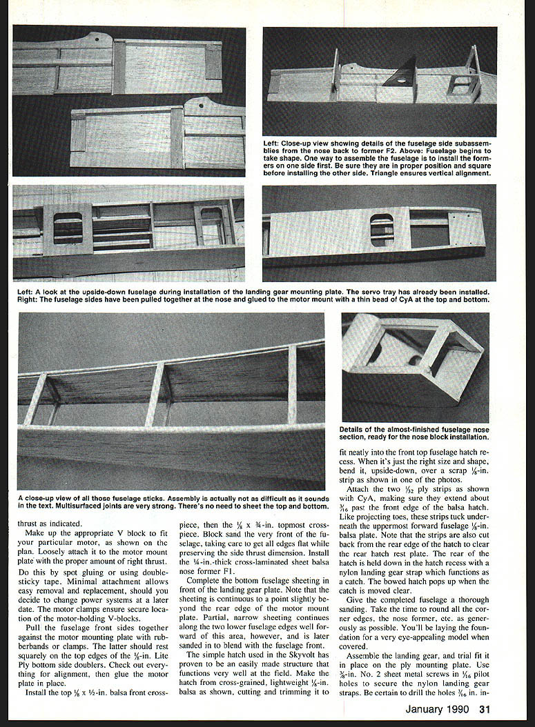
- Position and glue formers on one side, checking for orthogonality.
- Attach the opposite side substructure, clamp or rubberband, and use cyanoacrylate (CyA) to secure joints.
- Install 1/4 x 3/8‑in. battery support strips between formers F2 and F3. These help route cooling air among the battery cells and hold the battery pack upright to maintain a high center‑of‑gravity vertical location (improves roll performance).
- Block‑sand the fuselage bottom flat, install the 1/16‑in. landing gear plate, and attach bottom sheeting from F2 to beyond F4.
Assemble crosspieces:
- Cut 1/16 x 1/2‑in. strips and split each to make 1/4‑in. wide crosspieces.
- Install top and bottom crosspieces, raising the bottom ones 1/16 in.
- Install the rearmost top plywood tailwheel strut bearing plate, add 1/16‑in. top sheet and trailing edge stock at the stabilizer leading edge.
Add top sheeting just aft of F4, depressing it at F4 to form a V with the previously placed 1/16 x 1/2‑in. strip. Add 1/8 x 3/8‑in. longeron caps and 1/16 x 3/8‑in. crosspiece caps.
Flip fuselage, install bottom tailwheel strut bearing plate, bottom longeron and crosspiece caps. Make the rear hatch rest plate by adding a 1/8 x 1/2‑in. cross strip between the fuselage sides at the hatch rear and against F2 at the front.
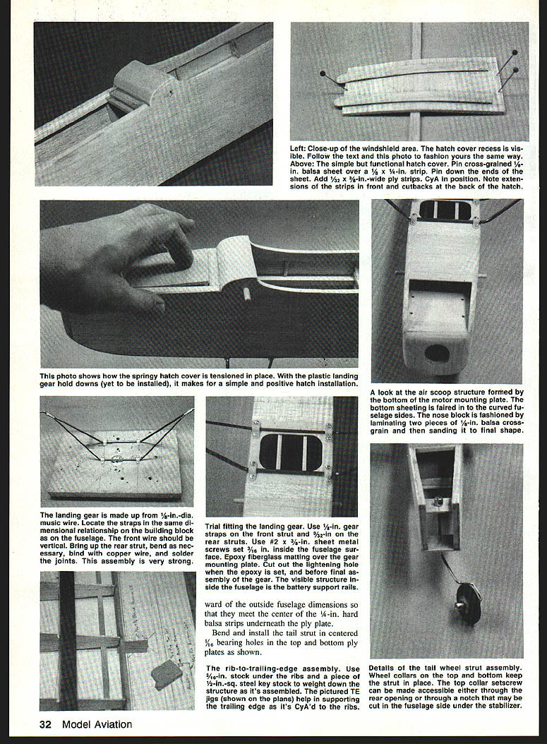
Windshield and nose:
- Install the balsa windshield from light 1/16‑in. A‑grain sheet, cutting 1/16 x 1/8‑in. notches in the fuselage sides for the bottom of the windshield.
- Trim 3/32 in. from the front edge of the right fuselage side to set the two degrees of right thrust.
- Make a V block to fit your motor and loosely attach it to the motor mount plate with a small amount of glue or double‑stick tape to establish right thrust. Use motor clamps for secure location.
Glue motor plate in place after aligning front fuselage sides and checking squareness. Install front crosspieces and the 1/4‑in. thick cross‑laminated sheet balsa nose former F1. Complete bottom sheeting in front of the landing gear plate; note sheeting continuity and partial lower edge sheeting forward of this area.
Hatch:
- Make the hatch from cross‑grained, lightweight 1/16‑in. balsa and fit it into the top fuselage hatch recess.
- Add two 3/32‑in. plywood strips to the hatch with CyA so they extend about 3/8 in. past the hatch front edge; these tuck under the forward fuselage plate and act as hooks.
- The rear of the hatch is held by a nylon landing gear strap which functions as a catch.
Finish fuselage:
- Sand and round corner edges generously.
- Assemble landing gear and trial‑fit to the ply mounting plate; use 3/32‑in. No. 2 sheet metal screws in 1/16‑in. ply holes and secure nylon landing gear straps. Drill holes 1/16 in. inward from outside fuselage dimensions to meet the center of the 1/4‑in. hard balsa strips under the ply plate.
- Bend and install the tail strut in centered 1/8‑in. bearing holes in the top and bottom ply plates.
Final assembly notes:
- Trial mount servos and make rudder/elevator pushrods; remove trial hardware and harden screw holes with a drop of thin CyA.
- At this point the fuselage structure should weigh about 3.5 oz.
Ailerons
Ailerons use an unusual hollow construction to save weight while remaining strong and twist‑resistant. Build them before the wings if you prefer.
Materials and method:
- Use less than two full sheets of 1/16 x 3 x 36‑in. balsa (C‑grain preferred) or 4‑in. wide stock. Choose the lightest wood you can find.
- Cut a 1 1/8‑in. wide Lite Ply template about 6 in. long. Cut one end of the balsa sheets at 45° and slice pieces using the template and a stop block to make the bottom surface segments.
- For top surface pieces, add a 1/16‑in. spacer to yield 1‑3/8‑in. wide sheets.
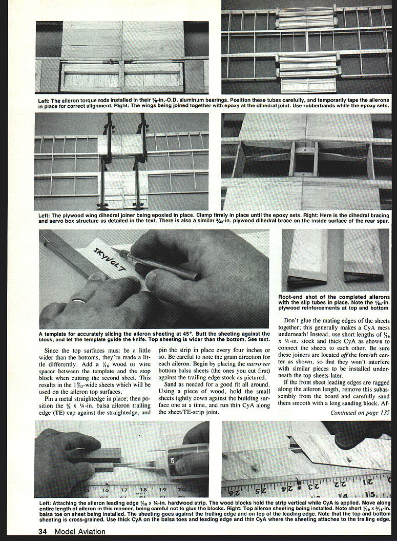
- Pin a metal straightedge and position a 1/8 x 1/4‑in. balsa aileron trailing edge (TE) cap, then glue the narrower bottom sheets to the TE cap using thin CyA along the sheet/TE joint.
- Do not glue mating edges of the sheets together. Use short lengths of 1/16 x 1/4‑in. stock and thick CyA as off‑center joiners to connect sheets. These joiners should be off the fore/aft center to avoid interference with top joiners later.
- Smooth ragged front sheet leading edges before installing top sheets.
- Glue top sheets cross‑grained to bottom sheets. Add 1/4 x 1/4‑in. joiners as you go, bonding joiner halves with thick CyA.
- Square ends, cap outer tips with 1/16‑in. sheet, rough carve and sand trailing edge strips to blend with taper.
- Notch root ends and CyA 3/4‑in. length of 3/32‑in. I.D. aluminum tubing in place; add root top and bottom 1/32‑in. ply. Keep tube interiors free of adhesive (these are aileron horn slip tubes).
Sand carefully—this is light wood and can be oversanded.
Wing
The wing construction is conventional with attention to accurate rib location and spar alignment.
- Mark rib locations on leading and trailing edge strips.
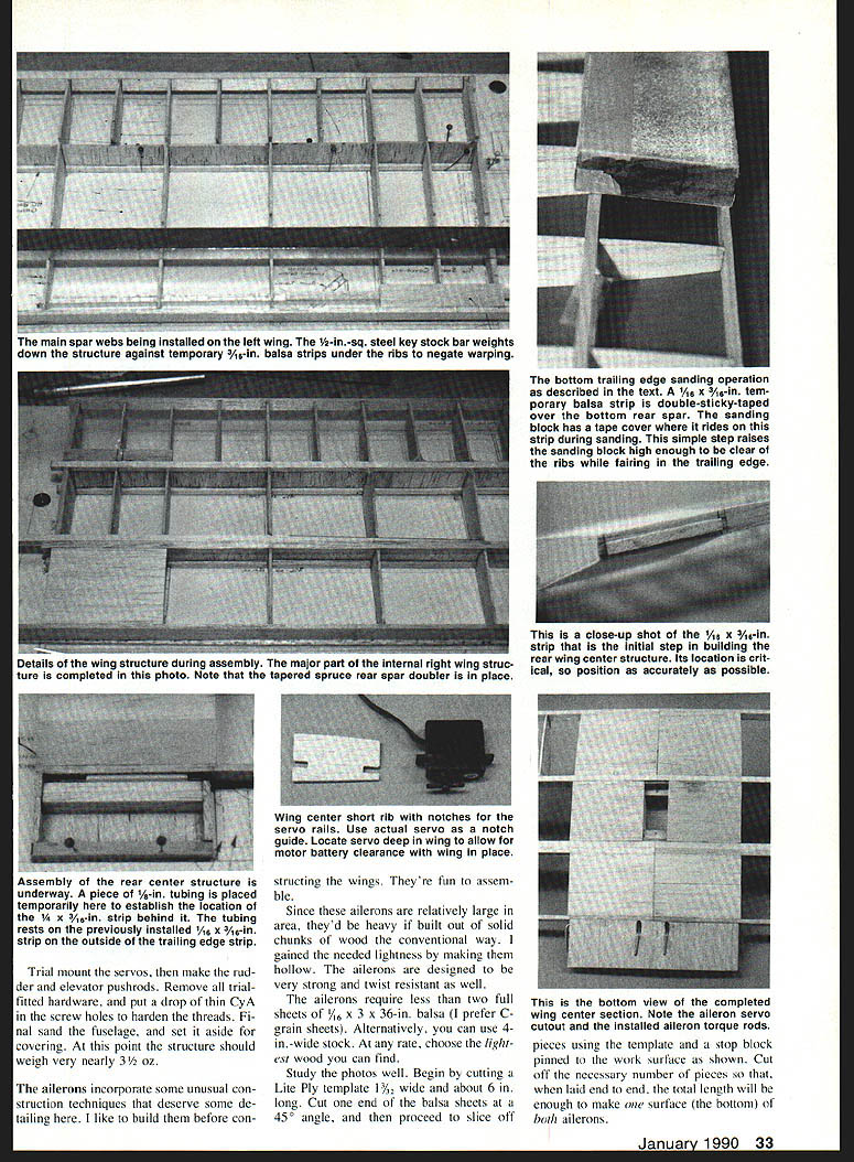
- Locate main bottom spruce spar over the plan and use a temporary 3/16‑in. balsa strip under ribs about 3/8 in. forward of the TE.
- Install all but the three center (root) ribs and CyA rib/spar joints. Bring the leading edge into position and apply CyA to leading edge/rib joints.
- Use a firm, straight 1/8 x 1/4‑in. balsa trailing edge. Support TE with jigs when CyA'ing ribs.
- Center section ribs are thinner to accommodate center sheeting; set 1/4‑in. root ribs using the dihedral angle guide on the plan.
- Install false ribs between leading edge and main spar and CyA in place.
- Install main spar webs and top main spruce spar, then rear top balsa spar and tapered spruce spar doubler.
- Flip panel, install rear spar webs, bottom rear spar, and tapered doubler. Complete top and bottom center section sheeting forward of main spar and rearward of rear spar (not between spars). Add 1/4‑in. tip plates.
Dihedral and center joiners:
- Sand root ends for a good dihedral fit. Actual dihedral at each tip under the main spar should be 1 in., ±1/8 in.
- Prefer dihedral joints made with Hobby Poxy Formula One: coat root end grains, set 20–30 minutes, then make joint, clamping for a few hours.
- Cut away four center‑most ribs, sand mating spar surfaces smooth, and epoxy 3/32‑in. plywood joiners in place. Joiners fit 1/16 in. inside top/bottom spar outer surfaces.
- Cut two short ribs for the servo box and notch for servo rails; locate servo close to the upper wing surface to maintain clearance when the wing is mounted.
- Install center section sheeting top and bottom between main and rear spars, keeping the servo box clear.
Aileron horn and bearings:
- Shape aileron horns from Goldberg .032‑in. horn wire using 3/32‑in. aluminum tubing as bearings.
- Drill clearance holes near the trailing edge for horn passage; temporarily fit and check alignment, then CyA the tube bearings in place.
- Cut and glue the single‑piece ply top wing center cover sheet carefully (avoid glue around horns/bearings).
- Wing woodwork including ailerons and horns should weigh about 6 oz.
Covering
- Final sand the completed structure before covering.
- The prototype used MonoKote; any film covering will work.
- Apply iron‑on cloth reinforcement in the landing gear mount area before covering the fuselage. Use a paper towel between the iron and the cloth to keep adhesive off the iron. Poke holes in the cloth at screw hole locations.
- Cover fin/rudder, stabilizer/elevator, wing, and ailerons separately.
- Do not cover glue joints that still require assembly.
Hinging:
- Check ailerons for warps before hinging. Use short balsa sighting sticks taped to the top surface at root and tip to check twist, and correct if necessary.
- Use tape hinges for ailerons; conventional hinges are acceptable for tails.
- Set a 1/16‑in. gap (or slightly less) before applying hinge tape.
Final assembly
- Glue fin to stab and glue the entire tail assembly to the fuselage.
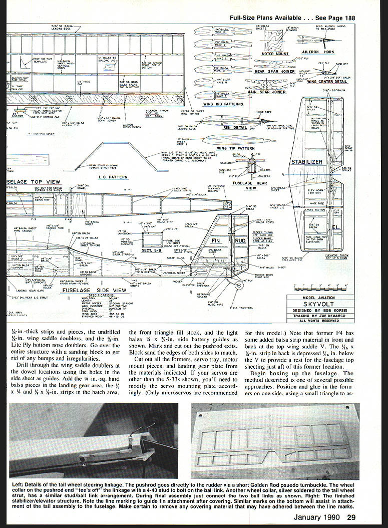
- Mount landing gear, wheels, and tailwheel assembly (landing gear hardware in total weighed about 2 3/8 oz. on the prototype).
- Install radio, connect rods and linkages, and check for smooth, nonbinding operation and correct throws. Make a small notch in the fuselage side for rudder horn throw clearance.
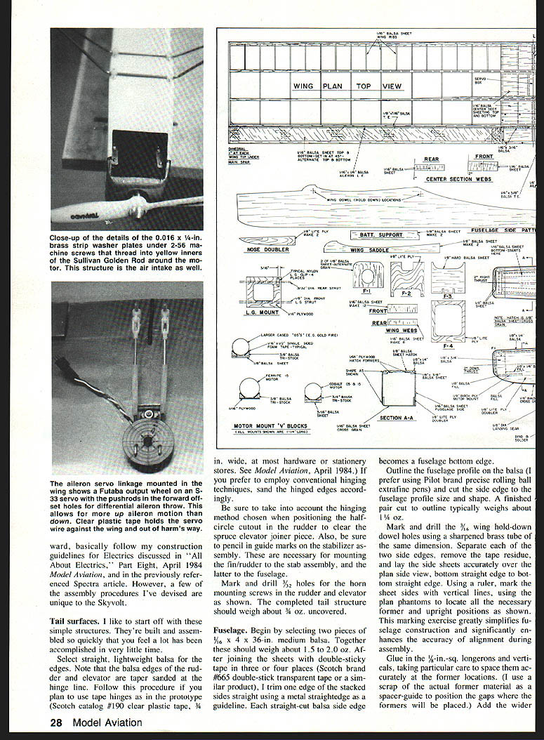
- Install wing servo and linkages. Note off‑center servo wheel pushrod holes to achieve aileron differential. Use short pieces (1–2 in.) of yellow inner Golden Rod tubing as turnbuckles to easily adjust rod lengths.
- With everything installed except power components, expect an empty weight around 22–24 oz.
Power installation and battery
- Note: common seven‑cell model car battery packs may not fit without modification. Reassemble packs to fit on the battery supports and between the inside fuselage battery guide strips (guides are 3/8 in. wide by 1/4 in. high).
- Fill leftover battery compartment space with custom‑fitted foam blocks to snug the pack and force cooling air among the cells. The pack must be tight enough to stay secure when the airplane is inverted.
- If needed, add small hooks to the upper surfaces of the side guides and loop rubber bands over the pack.
- Install wiring, speed control, and other interconnects behind the motor. Mount the speed control so the heat sink is in the airstream entering under the motor mount plate, but do not block air passage through former F2.
- Clamp the motor using yellow inners of small Sullivan Golden Rods as C‑clamps; cut rods short so they do not touch the motor mount plate and secure with 2‑56 screws. Tap the rod material with a 2‑56 tap first. Use 0.016 x 1/4‑in. brass strip washers under screw heads on the motor mount plate.
Electrics
Follow general electrics guidelines (see About Electrics, Part Eight, April 1984 Model Aviation, and the Spectra article). A few Skyvolt‑specific notes:
- The motor mount can accept two different motor sizes via V‑block cradles glued to the motor mount plate; use single‑sided 1/8‑in. foam tape on cradle edges and sandpaper strips to prevent slipping.
- Use microservos for the wing and small, light servos elsewhere as shown.
- Receiver battery may be relocated behind the servos on the 1/16‑in. fuselage bottom sheeting; use double‑stick Velcro (coat the sheeting with glue first and let dry so the Velcro sticks). If necessary, add a small tail weight to correct persistent nose‑heaviness.
Flight endurance examples (prototype):
- Gold Fire motor with seven 1.2‑Ah cells: flight times of 4 to 4½ minutes (48 oz. all‑up).
- Ferrite .15 on 12 x 900‑mAh cells: 4½ to 5 minutes (51 oz. all‑up).
- Gentler piloting and speed‑control management can extend flights to over 7 minutes.
Flying
Preflight and setup:
- Rubberband the wing in place and check clearances between motor, battery pack, and aileron servo/linkage—this is especially critical with taller 1,200‑mAh cells.
- If clearance is inadequate, try trimming the bottom battery rails about 1/8 in., using 1/4‑in. wing saddle tape instead of 1/16‑in., using a smaller servo, or remounting the servo deeper.
- Balance the model on the main spar (not forward or aft). The motor battery pack can be shifted fore/aft for balance if it has fewer than 12 cells; fill leftover space with foam. The receiver battery can be moved aft on the fuselage floor as noted.
- If all else fails, add a small amount of weight to the very rear of the fuselage to correct nose‑heaviness.
Flight handling:
- For first flights, a hand launch is recommended, especially with lower‑power systems.
- In a slight breeze the model will perform outside loops and consecutive rolls easily. Inside loops are definite and well directed.
- In moderate winds the model handles well; in light winds it remains easy to control.
- Given some headwind, short‑grass takeoffs are possible even with low‑end power systems.
- With higher power (cobalt .15s, 150–200+ watts) the Skyvolt becomes much more capable—faster acceleration, easier touch‑and‑go, and very square inside loops.
Adjust aileron throws depending on power and flying style: more throw for lower power, less for high‑powered systems. The plans show average throws; change them by adjusting the position of the screw‑on nylon pieces on the threaded horn.
Good luck with your Skyvolt. I hope you have as much fun and as many quiet flying hours as I have with mine. Please send comments, questions, or photos of your finished model. In closing, thanks to local modeler Bob Clauss for suggesting the model's name.
Transcribed from original scans by AI. Minor OCR errors may remain.

