
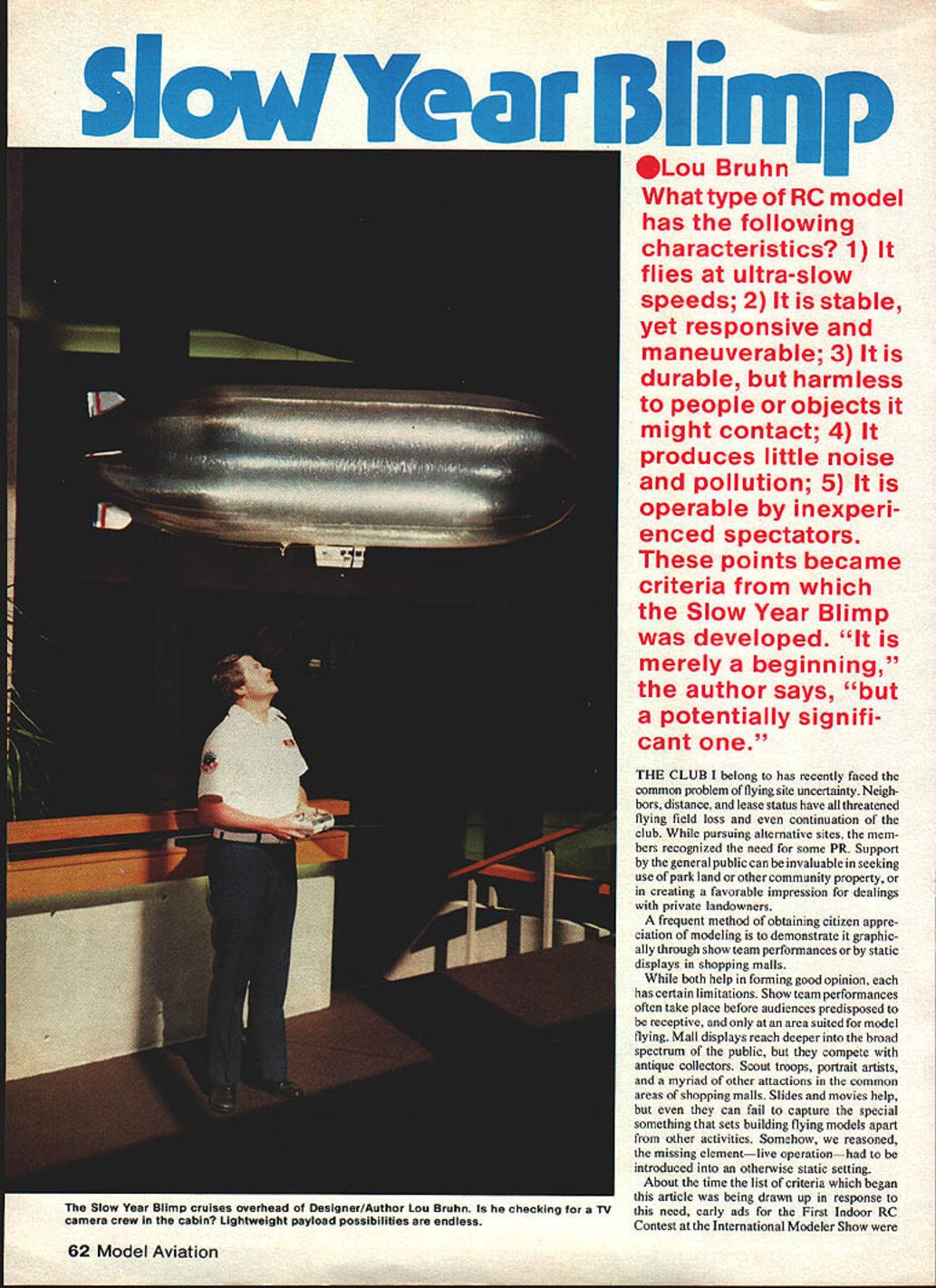
Slow Year Blimp
Lou Bruhn
What type of RC model has the following characteristics?
- It flies at ultra-slow speeds;
- It is stable, yet responsive and maneuverable;
- It is durable, but harmless to people or objects it might contact;
- It produces little noise and pollution;
- It is operable by inexperienced spectators.
These points became the criteria from which the Slow Year Blimp was developed. "It is merely a beginning," the author says, "but a potentially significant one."
The club I belong to has recently faced the common problem of flying site uncertainty. Neighbors, distance, and lease status have all threatened flying-field loss and even continuation of the club. While pursuing alternative sites, the members recognized the need for some PR. Support by the general public can be invaluable in seeking use of park land or other community property, or in creating a favorable impression for dealings with private landowners.
A frequent method of obtaining citizen appreciation of modeling is to demonstrate it graphically through show-team performances or by static displays in shopping malls. While both help in forming good opinion, each has certain limitations. Show-team performances often take place before audiences predisposed to be receptive, and only at an area suited for model flying. Mall displays reach deeper into the broad spectrum of the public, but they compete with antique collectors, Scout troops, portrait artists, and a myriad of other attractions in the common areas of shopping malls. Slides and movies help, but even they can fail to capture the special something that sets building-flying models apart from other activities. Somehow, we reasoned, the missing element—live operation—had to be introduced into an otherwise static setting.
About the time the list of criteria was being drawn up, early ads for the First Indoor RC Contest at the International Modeler Show appeared in magazines. In addition to heavier-than-air classes, the competition featured a lighter-than-air (LTA) category. The inspiration of this novelty, coupled with large doubt about satisfying all the preceding criteria with conventional heavier-than-air technology, led me to begin an investigation of LTA. Considering the possibility of eventual success, I added one more requirement to the list: construction should use only non-toxic materials and techniques, so others might readily duplicate the project.
Initial research showed that LTA was practically unknown to model magazine readers, aside from a handful of isolated efforts spread over many years. Nearly all these involved rigid dirigible frameworks and aerodynamic control surfaces. I soon ruled out rigid frameworks as too cumbersome to transport, time-consuming, and too easily damaged. Conventional control surfaces required constant forward motion and complex, extensive linkages. An alternative concept of a non-rigid blimp, controlled by directed thrust, began to take shape. With this arrangement there was the prospect of exceptional maneuverability, including reverse direction, turns in place, and nearly vertical ascents or descents.
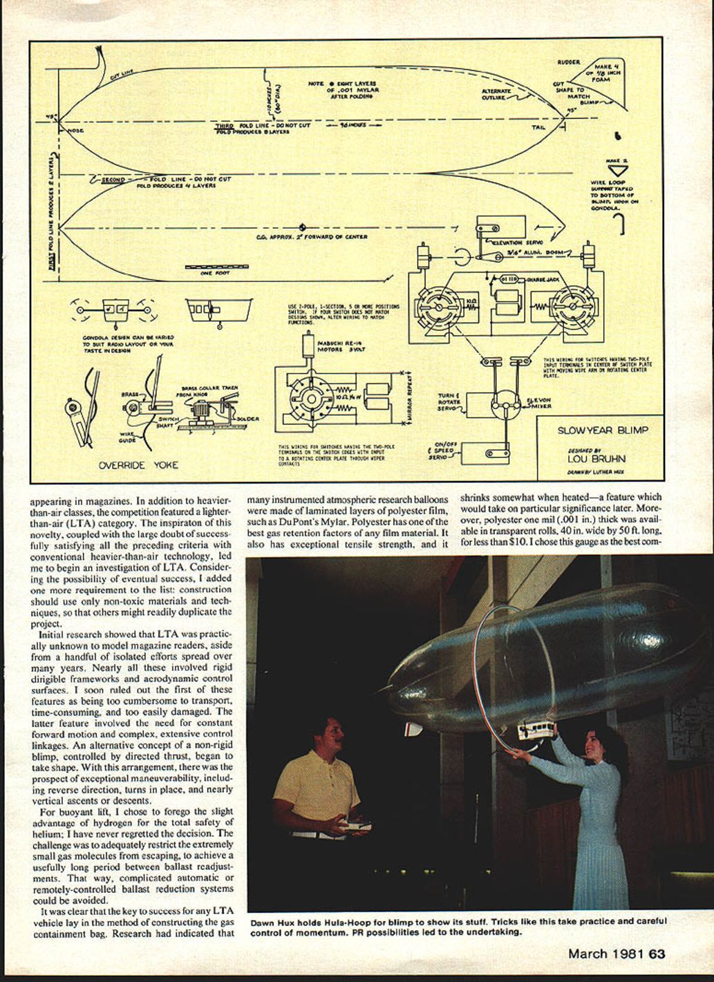
For buoyant lift, I chose the total safety of helium over hydrogen; I have never regretted the decision. The challenge was to adequately restrict the extremely small helium molecules from escaping in order to achieve a usefully long period between ballast readjustments. That way, complicated automatic or remotely-controlled ballast systems could be avoided.
It was clear that the key to success for any LTA vehicle lay in the method of constructing the gas containment bag. Research had indicated that many instrumented atmospheric research balloons were made of laminated layers of polyester film, such as DuPont's Mylar. Polyester has one of the best gas-retention factors of any film material. It also has exceptional tensile strength, and it shrinks somewhat when heated—a feature that would take on particular significance later. Moreover, polyester one mil (.001 in.) thick was available in transparent rolls, 40 in. wide by 50 ft. long, for less than $10. I chose this gauge as the best compromise between weight, strength, and gas retention.
The bag was made by folding and sealing eight layers of film together, producing a light, flexible, and reasonably gas-tight envelope suitable for model LTA work. For shape, the traditional blimp contours seemed a good bet, but with small tail surfaces so as not to hamper control while backing up. To ease the problem of making a closed container with multiple compound curves from a flat material, I planned to cut the tail fins from foam plastic meat trays and tape them in place.
The easiest way of forming the generally paraboloid shape at each end of the blimp was to attach tapering gore pieces alongside one another in a closed loop, in the manner of a parachute. With this technique, the surface contour becomes smoother as the number of individual gores increases. Clearly, some compromise was called for between aesthetics and spending the rest of my life fastening seams together. Impatient to see how the concept worked, I settled on only four gore pieces, stretching nose to tail and tapered at each end. As it turned out, this was ideal.
Mylar's high temperature tolerance makes heat-welding seams practical. Additionally, most modelers do not have access to heat-seaming equipment. A series of experiments was done to perfect an alternate method. Special contact cement could not be brushed on smoothly and uniformly enough. Tape looked promising, but how do you construct compound-curvature seams without a full-size form to build over? After much trial and error, the technique described below was developed and proved successful.
Construction
Before beginning, a number of things should be clearly understood.
- With its large surface area and very low mass, the blimp is affected by even the slightest air current, including those too faint for the pilot to sense. Heating or cooling system outlets, convection currents, or any outdoor operation are all impossible operating conditions unless you equip your blimp with extremely high-thrust capability. This has kept mine away from some otherwise prime sites, but not enough to say it wasn't all worthwhile. If in doubt, test the area first with a small helium balloon on a long string.
- Success depends on patient attention to repetitious actions. Helium escapes by any pathway offered, including right through the film material (at a low rate). Seams must be as near perfect as possible, or rapid loss of gas will drastically shorten operating time before ballast removal becomes necessary.
- This design represents only a first-generation stage of development. Follow the instructions and precautions fairly closely, and you should have a level of success similar to mine.
Rather than give only "fasten part A to part B" instructions, the following steps and notes focus on the technique.
Gas-bag assembly (seaming technique)
Key preparation points:
- Thoroughly clean a smooth hard surface (kitchen table top or similar Formica-like surface).
- Wipe film areas to be taped with acetone to remove grease or dust.
- Apply tape with extreme care—prevent bubbles or gaps, use as few pieces as possible, and avoid rough handling or sharp folds.
Seaming steps:
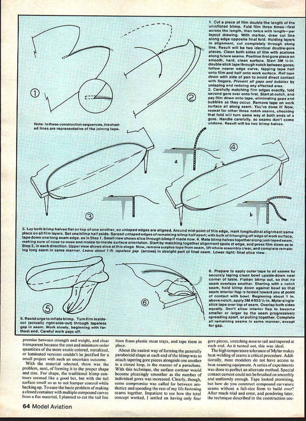
- Cut a piece of film double the length of the uninflated blimp. Fold film three times—first across the length, then twice with length—per layout drawing. With marker, draw a cut line along the edge opposite the final fold. Holding layers in alignment, cut completely through along the line. The result will be two identical double-gore pieces. Clean both sides of film with acetone along future seams. Position the first gore piece on a smooth, hard, clean surface.
- Start 3M 1/2-in. double-stick tape through the notch between gores; follow the nearer edge curve, lapping tape half onto film and half onto the work surface. Roll tape down with the side of a pen to avoid direct contact with fingers. Prevent all gaps and bubbles by untaping and redoing any affected area.
- Carefully matching film edges exactly, fold the second gore over onto the first. Start at the notch, and press the film down onto the tape, eliminating gaps and bubbles as they occur. Remove tape on the work surface all along the seam. Repeat for the other three notch seams, checking that the fold will turn the same way at both ends of a gore. Handle carefully so seams don't come undone. The result will be two blimp halves.
- Lay both blimp halves flat on top of one another so untaped edges are aligned. Around the midpoint of this edge, mark longitudinal alignment—the same place on all film layers. Set one blimp half aside. Spread untaped edges of the remaining blimp half apart; with most of it hanging off the edge of the work surface, tape down one long seam edge as in Step 1. Mate blimp halves together along the just-taped seam, making sure of nose-to-nose and inside-to-inside orientation. Start by matching together alignment spots at the edge, and press film down as in Step 2 in each direction. Remove surplus tape from the seam, lift the whole assembly clear, and complete the remaining long seam in the same manner. Leave about a 1-ft. tapeless gap in the straight part of the final seam.
- (Illustrations show seam cross sections and alignment details.)
- Resist the urge to inflate the blimp. Turn the film inside-out (actually right-side-out) through the tapeless gap in the seam. Work slowly, beginning with the farthest end. Careful work pays off.
- Prepare to apply outer tape to all seams by securely taping a clean bowl upside-down near a corner of the table. Flatten the blimp so no seam overlaps another. Starting with a notch seam, hold the blimp down against the bowl so that the seam interior flap is folded toward you at the point of contact with the bowl. Beginning about 1 in. above the notch, apply 3M #853 1/2‑in. Mylar single-stick tape over the top of the seam, overlapping both sides equally. Don't allow the interior flap to become smaller or larger by the seam progressively spreading apart or pulling together. Complete all remaining seams in the same manner, except for the tapeless gap.
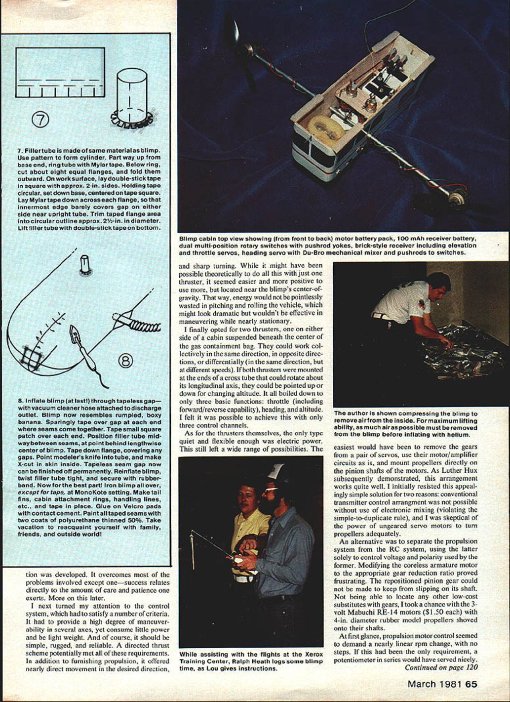
- The filler tube is made of the same material as the blimp. Use a pattern to form a cylinder. Partway up from the base end, ring the tube with Mylar tape. Below the ring, cut about eight equal flanges, and fold them outward. On the work surface, lay double-stick tape in a square with approximately 2‑in. sides. Holding the tube circular, set down the base, centered on the tape square. Lay Mylar tape down across each flange so that the innermost edge barely covers the gap on either side near the upright tube. Trim the taped flange area into a circular outline about 2‑1/2 in. in diameter. Lift the filler tube with double-stick tape on the bottom.
- Inflate the blimp (at last!) through the tapeless gap—use a vacuum-cleaner hose attached to the discharge outlet. The blimp will resemble a rumpled, boxy banana. Sparingly tape over the gap at each end where seams come together. Tape a small square patch over each end. Position the filler tube midway between seams, at a point behind the lengthwise center of the blimp. Tape down the flange, covering any gaps. Using a modeler's knife, make an X-cut in the skin inside the tube. The tapeless seam gap can now be finished off permanently. Reinflate the blimp, twist the filler tube tight, and secure with a rubber band.
- Iron the blimp all over (except for tape) at a MonoKote setting to shrink and smooth the film. Make tail fins, cabin attachment rings, handling lines, etc., and tape them in place. Glue on Velcro pads with contact cement. Paint all taped seams with two coats of polyurethane thinned 50%. Allow time for cure.
Modeling clay stuck around the single landing wheel on the bottom of the cabin enabled the blimp to be ballasted for neutral buoyancy after inflation.
Construction overcomes most problems involved except one—success relates directly to the amount of care and patience one exerts.
Control system
The control system had to provide maneuverability in several axes, yet consume little power and be lightweight. It should be simple, rugged, and reliable. A directed-thrust scheme met these requirements and offered nearly direct movement in the desired direction and sharp turning.
I opted for two thrusters, one on either side of a cabin suspended beneath the center of the gas containment bag. They could work collectively in the same direction, in opposite directions, or differentially. If both thrusters were mounted at the ends of a cross tube that could rotate about its longitudinal axis, they could be pointed up or down for changing altitude. It all boiled down to only three basic functions: throttle (including forward/reverse capability), heading, and altitude. I felt it was possible to achieve this with only three control channels.
Electric motors were the quietest and most flexible power source. The easiest approach would have been to remove gears from a pair of servos, use their motor/amplifier circuits as-is, and mount propellers directly on the pinion shafts. As Luther Hux subsequently demonstrated, this arrangement works quite well. I initially resisted this simple solution for two reasons: conventional transmitter control arrangement was not possible without electronic mixing (violating the simple-to-duplicate rule), and I was skeptical of un‑geared servo motors' power to turn propellers adequately.
An alternative was to separate the propulsion system from the RC system, using the latter solely to control voltage and polarity to the former. Modifying coreless armature motors to an appropriate gear reduction proved frustrating; repositioned pinion gears slipped on shafts. Not being able to find other low-cost geared substitutes, I used 4‑volt Mabuchi RE‑14 motors ($1.50 each) with 4‑in. diameter rubber model propellers shoved onto their shafts.
Propulsion control seemed to demand nearly linear RPM change, but there was a need to reverse electrical polarity after tapering down to power-off so a motor could then advance in the opposite rotation. Electronic throttles were too costly and heavy for this experiment. I hoped a multiple-position rotary switch could work if it enabled small enough stepped power changes in each direction. A pair of inexpensive 12-position electronic switches were modified to provide two-step, center-off, two-step reverse-polarity independent control of each motor. Mounting these switches in the appropriate position combinations required connecting their control shafts through a mechanical servo mixer, which blended two inputs.
Because the rotary switches were positioned by linear push-pull action, their travel had to be limited to less than 180° to avoid linkage jamming at the extremes. The commercial switches' contacts necessitated about 140° rotation to cover the full five-position sequence. To avoid jamming, a sliding pushrod/yoke arrangement was added to the switch shafts.
Packing the switches, mechanical mixer linkage, a three-channel radio system, a 2.4V 450 mAh drive-battery pack, and ballast into a sheet-balsa cabin made for a compact, serviceable, and simple arrangement. Adjustment of the mechanical mixer linkage and switch setup is the most critical aspect of assembly.
Switch modification (if needed)
Two types of switches are diagramed in the original plans. The Centralab 1002 is usable without modification. If it isn't available, a Radio Shack 12-position shorting type can be modified as follows:
- Remove the position-detent ball from the socket.
- Carefully remove the contact deck from the bottom of the switch.
- Use a file to divide the inner contact ring into two equal, unconnected semi-circular segments.
- Remove the switch shaft with rotating contact disc from the mounting assembly.
- Make, or cannibalize from another switch, a duplicate metal contact piece like the one already mounted on the rotating contact disc.
- Securely fasten this new piece onto the rotating contact disc so that it will contact the bottom-deck contacts 180° from the original contact piece.
- Adjust contact tension to be positive but free, and reassemble all switch elements.
Remove the metal insert collar from an electric knob, slide it fully onto a switch shaft, and tighten the set screw. Make a brass or tin yoke and solder it onto the collar. Cut the switch shaft 1/8 in. above the collar. Make and solder the pushrod retainer/guide to the switch mounting washer. Wire the switch circuit and test thoroughly before installing it into the cabin.
Operation
If you're satisfied with all preliminary inflation checks using plain air, detach the cabin and work as much air out of the bag as possible. Suck through the fill tube to collapse it flat. Install a balloon inflation valve onto the compressed helium cylinder. I prefer to lay the cylinder on its side with the inflation nipple angled upward. Get an assistant and take precautions to retain the blimp as you inflate through the fill tube. When half full, the cabin can be reinstalled.
Continue inflation until just full—overfilling reduces buoyancy, increases gas-leakage rates, and stresses seams. Squeeze off the fill tube near the upper end, twist the lower portion tightly, fold it over upon itself, and loop a rubber band repeatedly around the prior fold to secure. Adjust ballast for neutral buoyancy. Eureka! It floats in midair!
Charge batteries fully. I use the Astro Flight 15‑minute formula for the receiver battery and a simple Amps × time charge into a thoroughly depleted propulsion battery. With the sizes used, operation averages about 25 minutes.
It's hard to believe the genuine excitement of a novice learning to fly the blimp in a confined space like a living room. Although weightless, the blimp's inertia continues, with power off, in whatever direction it was headed last. To avoid (probably harmless) collisions with lamps, plants, candles and other objects requires frantically reversing control at maximum power.
Finesse is required to control momentum with the limited thrust available. Eventually vertical ascents and descents and spot landings become routine, and the blimp can be flown through a hula hoop—both backwards and forwards. In calm air the degree of control seems practically unlimited. Larger areas allow more relaxed operation, but heading directional stability over a long straight run is marginal with the small tail fins. Nevertheless, there's always a line for a turn at the sticks! Just watch your battery charge.
The blimp is small enough to be transported intact in the rear of a compact station wagon with the back seat folded down. Rapid temperature changes from outdoors to indoors can dramatically change skin tension temporarily; allow some time for internal temperature to stabilize before readjusting inflation.
Flight characteristics and tips
- Test the area first with a small helium balloon on a long string to detect drafts.
- Let off commands before you get to where you want to go; inertia will carry the blimp beyond your target.
- Expect limited thrust and learn to manage momentum with gentle, anticipatory control inputs.
- In buildings with heavy air-conditioning the blimp may be pushed around a lot; ventilation patterns can make control challenging and reduce flight time.
Public demonstrations and anecdotes
Many people had not yet seen the blimp when we first demonstrated it publicly. On one occasion a candidate began remarks, paused, and stared at the balloon and the banner. A TV reporter asked us to fly during the next break to film it. That evening our first public flight appeared briefly on TV.
Some conventions were more exciting than others—not the program, but the flights. In buildings with heavy air-conditioning the blimp could be tossed around by vents. Occasionally someone in the crowd would try to help and give it a push; the blimp would shoot to the ceiling and bounce. I would scramble to be where it was coming down, even though it could not hurt anyone if it settled on them. One lady, puzzled by the transmitter, took it out of my hands. When I told her "it's the control to the balloon, and without it I'm about to crash," she handed it back like a hot potato and disappeared into the crowd.
After one convention I offered Bill Winter a chance to fly it in his home. His exuberant "bull-in-a-china-shop" reaction was a surprise—an 8‑ft. ceiling and a room of furniture make for a lot to handle. In a gym he might have enjoyed it more.
Because of busy schedules, my balloon and Lou's blimp did not fly together for some time. Then Chuck Thomas arranged a Saturday morning session at the Xerox Training Center for photography. Imagine Xerox students strolling through the mezzanine and finding a hot-air balloon and a blimp waltzing about the building—their wide-eyed reactions were a lot of fun. Our thanks to Ralph Heath for escorting us for the four-hour photo session.
Future development
This concept begs for modification. Examples:
- Use colored or metalized "high-priced spread" film for a more impressive look.
- Simplify the seam-making technique.
- Develop the control system further: electronic mixing, geared servo-motor thrusters, different thruster placement.
- Explore payloads: airborne P.A. systems, signs, banners, light-bulb chargers, etc.
Have a ball. Just be sure to pass your improvements along.
The plans tell most of the story for building the blimp, but a problem for some will be in where to fly it.
Transcribed from original scans by AI. Minor OCR errors may remain.

