
Sly Sir
Text and photos by Rich von Lopez
Overview
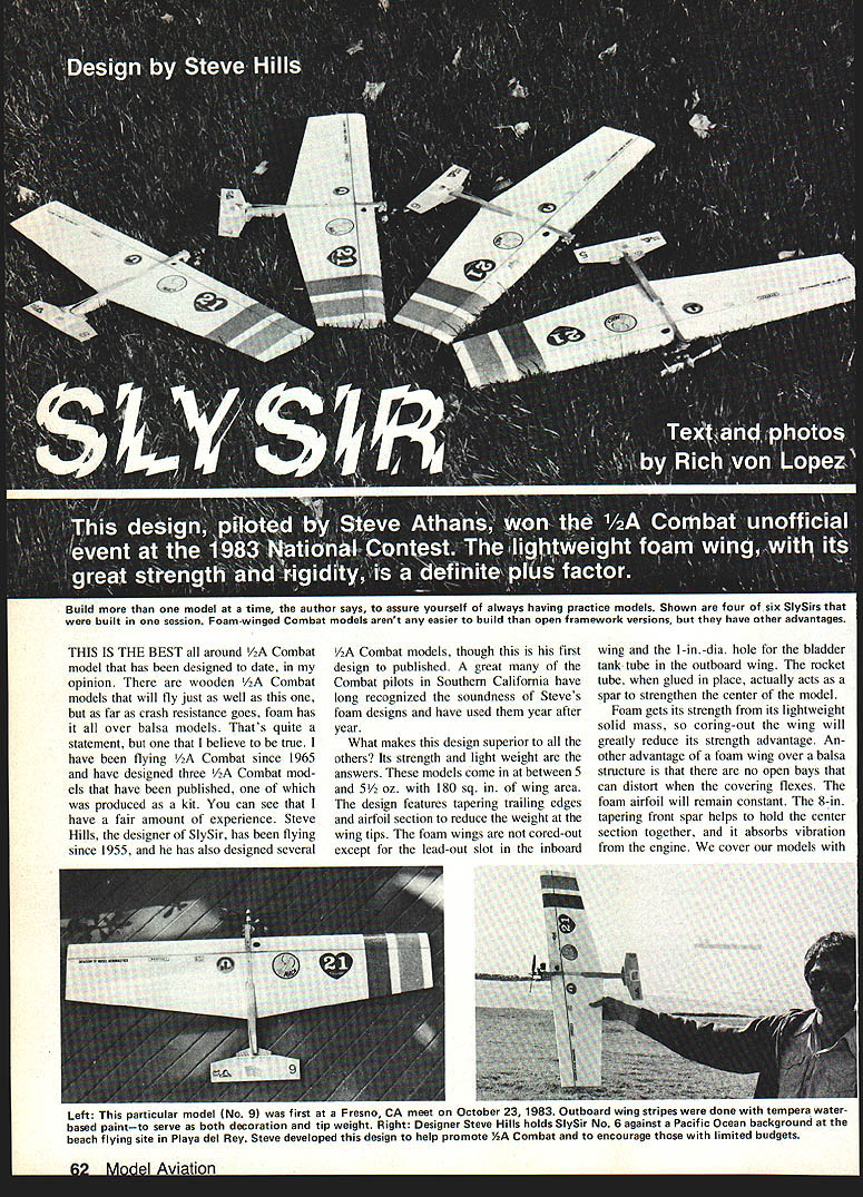
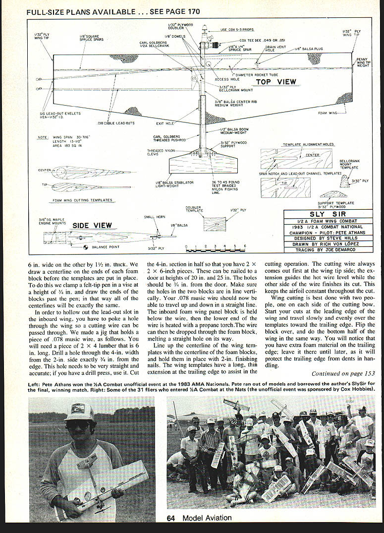
This design, piloted by Steve Athans, won the 1/2A Combat unofficial event at the 1983 National Contest. It is, in my opinion, the best all-around 1/2A Combat model designed to date. Weighing between 5 and 5-1/2 oz with about 180 sq. in. of wing area, the Sly Sir combines light weight, strength and crash resistance thanks to its solid foam wing and careful structure. Steve Hills (designer of Sly Sir) has been flying since 1955; many Southern California Combat pilots have long valued his foam designs.
Build more than one model at a time to ensure you always have practice models. Foam-winged Combat models aren't necessarily easier to build than open-framework balsa versions, but they have advantages: greater crash resistance, consistent airfoil under covering, and quicker, easier repairs.
Design features and advantages
- Foam wing: solid foam gives strength from lightweight mass. Wings are not cored out except for the inboard lead-out slot and a 1-in. dia. hole for the bladder-tank tube in the outboard wing.
- Tapered trailing edges and airfoil at the tips reduce weight at the wing tips.
- Rocket (bladder) tube glued in place acts as a spar to strengthen the center.
- 8-in. front spar helps hold the center section together and absorbs engine vibration.
- FasCal Mylar covering (sticky adhesive side) adds overall strength.
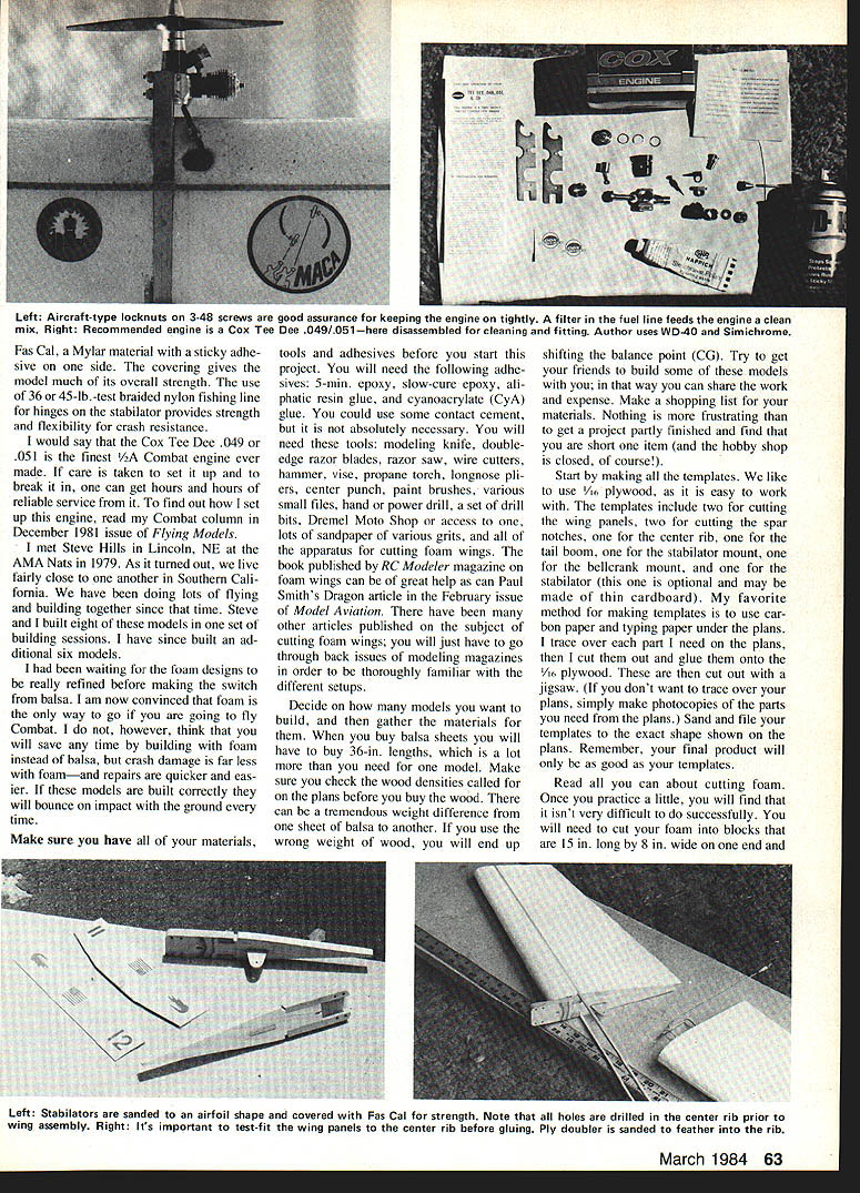
- 36–45-lb.-test braided nylon fishing line hinges on the stabilator provide strength, flexibility and crash resistance.
- Recommended engine: Cox Tee Dee .049/.051 (careful setup and break-in yield long, reliable service).
Before you start
Make sure you have materials, tools and adhesives before starting. It saves time and prevents frustration.
Adhesives
- 5-minute epoxy
- Slow-cure epoxy
- Aliphatic resin glue
- Cyanoacrylate (CA) glue
- Optional: contact cement
Tools
- Modeling knife and double-edge razor blades
- Razor saw
- Wire cutters
- Hammer and vise
- Propane torch
- Long-nose pliers
- Center punch
- Paint brushes, various small files
- Hand power drill and drill bits
- Dremel / Moto-Tool access
- Lots of sandpaper in various grits
- Apparatus for cutting foam wings (see references below)
- Jigsaw for cutting templates
- Sewing needles (sizes 18–22) for stabilator hinges
- Small Hi-Johnson fuel filter and syringe for filling bladders
References
- RC Modeler magazine book on foam wings
- Paul Smith's "Dragon" article in Model Aviation (February issue)
- Back issues of modeling magazines for various foam-cutting setups
Planning and templates
- Decide how many models to build and gather materials.
- Buy balsa sheets in 36-in. lengths where called for by the plans.
- Check wood densities on the plans before purchase to avoid undesired weight/CG shifts.
- Make templates from 1/16-in. plywood for: two wing panels, two spar-notch guides, center rib, tail boom, stabilator mount, bellcrank mount, and stabilator (optional: thin cardboard).
- My preferred method: trace parts from plans with carbon paper and typing paper, glue traced patterns to 1/16-in. plywood, then cut out with a jigsaw and finish with sanding/files. Photocopying parts is an alternative.
- Remember: final quality is limited by template accuracy.
Cutting foam wing cores
Foam block size and centerline
- Cut foam blocks 15 in. long by 8 in. wide on one end and 6 in. wide on the other, 1-1/2 in. thick.
- Draw a precise centerline on the ends of each foam block. A simple jig: clamp a felt-tip pen in a vise at 1/4 in. height and slide the block past the pen so all centerlines match exactly.
Jig for making the lead-out hole through inboard wing
- Use a piece of 2 x 4 lumber, 6 in. long. Drill a hole through the 4-in. width from the 2-in. side exactly 3/4 in. from the edge. Accuracy is important—use a drill press if possible.
- Cut the 4-in. section in half to produce two 2 x 2 x 6-in. blocks. Mount them on a board at heights of about 20 in. and 25 in. so their holes line up vertically and a .078-in. music wire can travel straight up and down.
- Hold the inboard foam block below the wire, heat the lower end of the wire with a propane torch and drop it through the foam to melt a straight hole for the lead-out slot starter.
Cutting wings with a hot wire
- Align wing templates on the foam block centerline and hold with 2-in. finishing nails. Wing templates have a thin trailing-edge extension to guide the cutting wire level.
- Hot-wire cutting is best with two people—one on each side of the bow. Start at the leading edge and travel slowly and evenly toward the trailing edge. Flip the block and cut the bottom half similarly.
- Leave extra foam on the trailing edge for protection during handling and until later trimming.
- Practice on scrap foam until you get a consistent cut. Coring out the wing reduces strength; do not core except where specified.
Spar notches and lead-out slot
- Cut spar notches with the same bow, using the spar-notch templates in the same nail holes.
- Cut down the front, across the bottom, then up the back. Avoid lingering in one spot or you will over-melt the foam.
- After the first panel, check spar groove fit with spruce spars and adjust templates if necessary.
- For the lead-out slot: leave templates in place on the inboard panel, pass the cutting wire through the hole made earlier (.078 music wire hole) by taping the cutting wire to the music wire and pushing through. Hold each end of the cutting wire with surgical forceps and connect alligator clips to your power source. Go around the slot twice, stop in the center and let the wire cool. Pull the cutting wire out from the center rib side so the cut foam comes out; poke out remaining foam with a wing spar.
Bladder tank tube hole
- Cut the 1-in.-dia. bladder tank tube hole in the outboard wing with a sharpened 1-in. aluminum tube (a shower curtain rod works). Mark the tube at 5-1/2 in. with masking tape to avoid cutting too far.
- The round foam plug may fall out or be tapped out with a small dowel. Slip the aluminum tube in; it should be snug. Glue it with 5-minute epoxy. If too tight, sand the tube lightly to fit.
Wing tips, joining panels and spars
- Glue 1/32-in. plywood wing tips on before joining outboard panels. Cement with 5-minute epoxy and pin until cured, then shape with Dremel/sanding drum to match the wing taper.
- Glue outboard wing panel to inboard using 5-minute epoxy. Clamp lightly and wipe excess epoxy with acetone before it cures.
- When installing main spars, push into slots, set dihedral breaks, tape in place and run a bead of epoxy top and bottom to lock them. Use hot-melt to tack the center block while epoxy cures or it may float.
- Use matching wing-panel cradles on a flat surface to hold wings aligned while top and bottom spars are glued with aliphatic-resin glue. Weight the spars while drying. Sand spar ends flush with wing tips afterward.
Final wing shaping and fittings
- Trim excess foam from the trailing edge with a razor blade and metal yardstick; leave the trailing edge square and sharp rather than rounded or thinned.
- Press 1/32-in. lead-out eyelets into the inboard wing tip and CA-glue them. Fill gaps with microballoons or baking soda. Be careful not to cross lead-outs when feeding them through.
- Glue 1/32-in. plywood wing tips to the foam with 5-minute epoxy or contact cement for foam.
- Make all lead-outs the same length—about 2-1/2 in. extending beyond the wing tip—for consistent handle feel between models. Use brass/copper tubing crushed or crimped to lock the lead-out ends.
Fuselage, mounts and center rib assembly
- Build the fuselage over a simple hardwood board: pin fuselage sides down, align firewall and rear tailpost with the plan, and glue formers in place.
- Use 1/16-in. plywood doublers at the wing saddle and stab mount to reinforce high-stress areas.
- Epoxy the stab in place after fusing the fuselage; leave it in the building jig until epoxy cures.
Rocket tube preparation
- Cut 1-in.-dia. rocket tube (Estes BT50) to 5-1/2 in. length. Tubes come in 18-in. lengths.
- Coat the inside with slow-cure epoxy, fiberglass resin, or polyurethane varnish; let dry (overnight preferred).
- Sand the inside smooth with rolled fine sandpaper to remove sharp edges that could rupture the bladder.
- Cut two round balsa plugs for the ends and glue with 5-minute epoxy, ensuring inside surfaces have epoxy coat.
- Sand the outside, coat with a thin layer of aliphatic resin glue, and slide into the wing hole—do not let it extend beyond the wing edge.
Engine mounts and doublers
- Glue two maple engine mounts to the center rib with aliphatic resin. Glue 3/32-in. plywood engine-mount doubler in place.
- Cut a 1/4 x 7/8-in. rectangular hole in the doubler for the front spar: drill a hole and carve out with a modeling knife.
- Shape mounts to the plan, taper the rear of the doubler flush with the rib, and center-punch and drill engine bolt holes.
- Put CA down each engine-bolt hole so glue soaks into the wood; then redrill the hole to fuel-proof them.
- Drill and glue dowels in place where shown on the plans.
Bellcrank and pushrod installation
- Cut the bellcrank mount slot in the center rib and drill two 3/32-in. holes at the slot ends. Use a modeling knife and small file to shape the tapered slot so the bellcrank mount cannot pull out.
- Glue bellcrank mount in slot with aliphatic resin.
- Attach .018 stranded lead-out cables to a 1/32-in. bellcrank (C. Goldberg #263 or Sig #SH 234). Sand the lead-out holes to remove sharp edges.
- Enlarge the pushrod hole in the bellcrank as needed to accept the threaded pushrod.
- Leave 1-1/2 to 2-in. loops in the lead-outs between the bellcrank and flattened brass/copper attachment pieces—flatten by placing the tubing in a vise and hitting with a hammer or use a crimping tool.
- Bend and cut the pushrod to plan shape, slip into the bellcrank and bolt the assembly to the bellcrank mount. Replace the wood screw from the bellcrank set with a bolt and nut. Add a drop of oil to the bellcrank bushing for smooth operation; trim excess bolt.
- Glue dowels and other small parts as specified with aliphatic resin.
Wing-to-center rib bonding
- Prepare the inboard half first. Spread epoxy only on contact surfaces and avoid getting epoxy on lead-outs, bellcrank, pushrod, spar notches and front-spar groove.
- Use the front spar and scrap spar material to help locate the wing. When pressing the wing to the center rib, lift the trailing edge slightly to the center of the rib. Temporarily hold with masking tape until glue hardens. Remove scrap spars so stray epoxy won't glue them in place.
- For the outboard panel, coat the outboard side of the center rib and front-spar grooves with enough epoxy. Slide the front spar through the engine-mount doubler into the inboard groove, use scrap spars extending 2 in. into the outboard wing as guides, align trailing edges, and tape into place until epoxy hardens.
Leading-edge groove and inboard trimming
- Cut a tapered groove in the wing leading edge to accept the tapered front spar. Mark with felt-tip pen, cut with a modeling knife and sand to fit. A sanding tool made from sandpaper glued to a scrap 1/8-in. sq. spar helps.
- Trim inboard foam so the bellcrank area and engine-mount doublers fit without binding—remove only what is necessary to avoid weakening the section.
- Meter out the pushrod exit slot in the wing with a hot wire and avoid making it too large.
Covering, stabilator and finishing
- Cover the wing with FasCal Mylar on top and bottom. The sticky adhesive side adds structural strength. Use a sealing iron (experiment on scrap to get heat right—our iron uses about 450°F at its maximum setting). Heat guns often get too hot and will melt the foam.
- For extra strength, add a 4-in.-wide double layer of FasCal over the center section.
- Sand the FasCal slightly where the tail boom will sit and glue the tail boom in place with 5-minute epoxy.
- Sand the stabilator to an airfoil shape. Add nylon hinge material where the control horn mounts and glue with CA. Cover the stab with FasCal and add a double layer to the leading edge where it will be sewn to the mount.
- Sew on the stabilator using 36–45-lb.-test braided nylon fishing line: tie a knot on a 36-in. length, melt the end to secure it, pass the line only twice through each hole, align the stabilator with the wing trailing edge before tightening, then tighten and apply a drop of CA in each hole. Trim excess line.
- Locate and pilot-hole the control-horn location with a pin, screw on the control horn, hook up a mini snap clevis and adjust the pushrod so there is equal up/down travel. Use the top hole on the control horn.
- Epoxy one penny to the outboard wing tip between the spars for added tip weight. Coat wing tips and all FasCal edges with clear polyurethane varnish to fuel-proof the structure.
- Bolt on your Tee Dee .049 or .051.
Paint, decals and identification
- If decorating, do it before final varnish. Pre-mixed tempera paint works on foam but is heavy—use sparingly. A simple stripe or two on the outboard wing aids judge visibility and scoring.
- Put your AMA number and name on the model.
Fuel system and bladders
- 1/2A Combat uses .012 line of 35-ft. length. Use the inside holes of a small Sullivan Pylon handle (II-2).
- Fuel: Cox Tee Dee .049s like a good bit of nitromethane—about 25% is commonly used.
- Bladders: use 3/16-in. latex tubing; 1/32-in. wall works well.
- Fuel line: very small black neoprene tubing works well. Use a small Hi-Johnson fuel filter.
- Filling bladders: use a disposable plastic syringe and fabricate an adapter from medium fuel tubing and a 2-in. length of 3/32-in. brass or copper tubing so the syringe will fit the small neoprene fuel line. Fasten adapter to syringe securely (copper wire is suggested).
Final checks and flying
- Check for warps before the first flight. If warps occur after initial flights, iron them out with your covering iron.
- Adjust pushrod and control horn to achieve the desired turning radius.
- Practice Combat flying extensively until you know what the model can do.
Suppliers
- Sly Sir wing cores are available from Phil Carter / Core House, Box 300A RD #2, Palmyra, PA 17078. Write for prices.
Good luck and happy flying!
Transcribed from original scans by AI. Minor OCR errors may remain.

