
Small-Field Flying
Larry Marshall 51 Blvd. des Allées, Québec, QC G1L 1Y3, Canada; E-mail: larrym@sympatico.ca
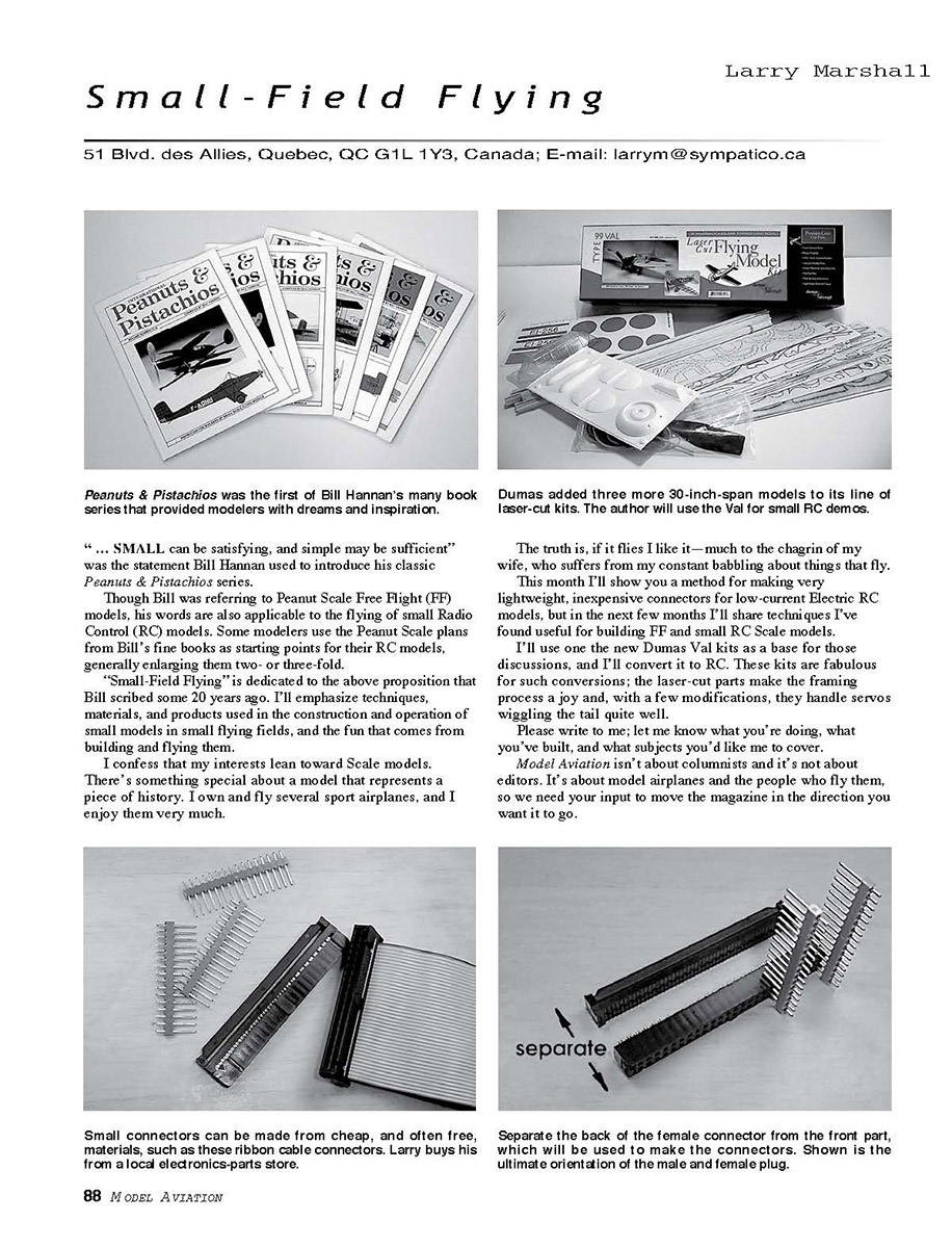
“…SMALL can be satisfying, and simple may be sufficient” was the statement Bill Hannan used to introduce his classic Peanuts & Pistachios series. Though Bill was referring to Peanut Scale Free Flight (FF) models, his words are also applicable to the flying of small Radio Control (RC) models. Some modelers use the Peanut Scale plans from Bill’s fine books as starting points for their RC models, generally enlarging them two- or three-fold.
“Small-Field Flying” is dedicated to the above proposition that Bill scribed some 20 years ago. I’ll emphasize techniques, materials, and products used in the construction and operation of small models in small flying fields, and the fun that comes from building and flying them.
I confess that my interests lean toward scale models. There’s something special about a model that represents a piece of history. I own and fly several sport airplanes, and I enjoy them very much. The truth is, if it flies I like it—much to the chagrin of my wife, who suffers from my constant babbling about things that fly.
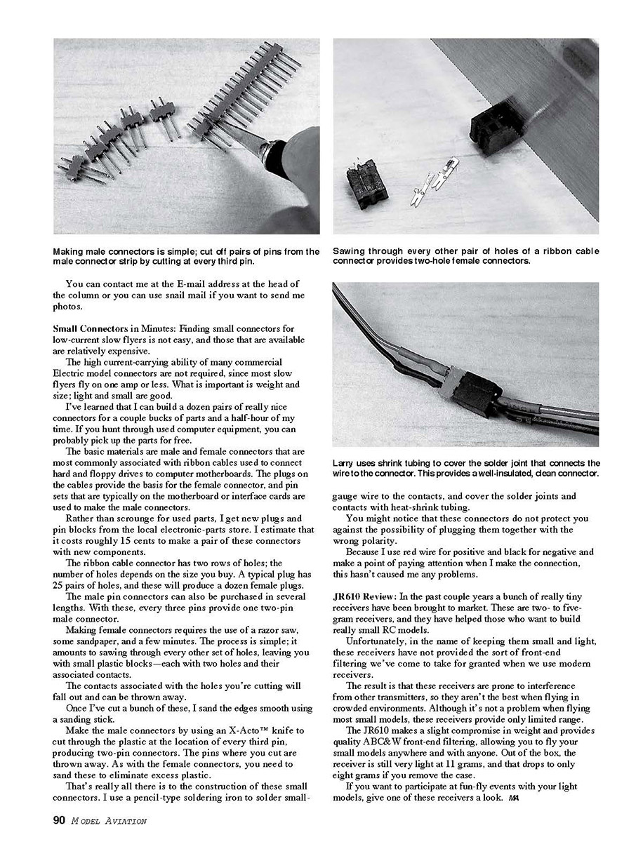
This month I’ll show you a method for making very lightweight, inexpensive connectors for low-current electric RC models, and in the next few months I’ll share techniques I’ve found useful for building FF and small RC scale models.
I’ll use one of the new Dumas Val kits as a base for those discussions, and I’ll convert it to RC. These kits are fabulous for such conversions; the laser-cut parts make the framing process a joy and, with a few modifications, they handle servos wiggling the tail quite well.
Please write to me; let me know what you’re doing, what you’ve built, and what subjects you’d like me to cover. Model aviation isn’t about columnists and it’s not about editors. It’s about model airplanes and the people who fly them, so we need your input to move the magazine in the direction you want it to go.
Small Connectors in Minutes
Finding small connectors for low-current slow flyers is not easy, and those that are available are relatively expensive. The high current-carrying ability of many commercial electric model connectors is not required, since most slow flyers draw one amp or less. What is important is weight and size; light and small are good.
I’ve learned that I can build a dozen pairs of really nice connectors for a couple bucks of parts and a half-hour of my time. If you hunt through used computer equipment, you can probably pick up the parts for free. The basic materials are male and female connectors that are most commonly associated with ribbon cables used to connect hard and floppy drives to computer motherboards. The plugs on the cables provide the basis for the female connector, and pin sets that are typically on the motherboard or interface cards are used to make the male connectors.
Rather than scrounge for used parts, I get new plugs and pin blocks from the local electronic-parts store. I estimate that it costs roughly 15 cents to make a pair of these connectors with new components. The ribbon cable connector has two rows of holes; the number of holes depends on the size you buy. A typical plug has 25 pairs of holes, and these will produce a dozen female plugs.
Making the female connectors requires only a razor saw, some sandpaper, and a few minutes. The process is simple: saw through every other set of holes, leaving you with small plastic blocks—each with two holes and their associated contacts. The contacts associated with the holes you're cutting will fall out and can be discarded. Once I've cut a bunch of these, I sand the edges smooth using a sanding stick.
Make the male connectors by cutting the plastic at the location of every third pin on a pin strip, producing two-pin connectors; the pins where you cut are discarded. An X-Acto knife works well for this. As with the female connectors, you need to sand these to eliminate excess plastic.
That's really all there is to the construction of these small connectors:
- Cut the ribbon-cable plug into two-hole female blocks by sawing through every other set of holes. Discard loose contacts.
- Cut the pin strip into two-pin male blocks by slicing through every third pin. Discard the cut pins.
- Sand all cut edges smooth.
- Solder small-gauge wire to the contacts using a pencil-type soldering iron.
- Cover solder joints and contacts with heat-shrink tubing.
You might notice that these connectors do not protect you against the possibility of plugging them together with the wrong polarity. Because I use red wire for positive and black for negative and make a point of paying attention when I make the connection, this hasn't caused me any problems.
JR610 Review
In the past couple of years a bunch of really tiny receivers have been brought to market. These are two- to five-gram receivers, and they have helped those who want to build really small RC models.
Unfortunately, in the name of keeping them small and light, these receivers have sometimes omitted the sort of front-end filtering we've come to take for granted in modern receivers. The result is that they can be prone to interference from other transmitters, so they aren't the best choice when flying in crowded environments. Although it's not a problem when flying most small models, these receivers provide only limited range.
The JR610 makes a slight compromise in weight and provides quality front-end filtering, allowing you to fly your small models anywhere and with anyone. Out of the box, the receiver is still very light at 11 grams, and that drops to only eight grams if you remove the case.
If you want to participate at fun-fly events with your light models, give one of these receivers a look. —LM
Transcribed from original scans by AI. Minor OCR errors may remain.

