
Smsmosmoosmoother
At the 1983 Nationals I had many people ask if the Stunter I was flying was a modified Smoothie. In fact, it was a modified Thunderbird. I began to feel obliged to build a modified Smoothie to show the difference. The result is the model you see here.
I am drawn to older, more classic designs—such as the Smoothie and Thunderbird—but in general I haven't been satisfied with some original design characteristics. This model, like the modified Thunderbird presented as the Phoenix construction article in a recent issue of Model Aviation, has many changes made to accommodate the current standards for performing the AMA Precision Aerobatics pattern.
The original Smoothie was designed by Bob Palmer and presented in the August 1952 issue of Air Trails as Palmer's answer to windy weather conditions. As originally published, it had quite short moment arms, small flaps, very little flap movement, and a unique airfoil with a very aft high point. This worked quite well for the 1952 pattern, which had only one square loop. Palmer even took second place in the 1952 Nationals with his original model.
The Veco (later Dumas) kit version had minimal structural changes, was better looking, and also included details for an inverted‑cowled engine. This was the model shown on the kit box. Palmer's first Smoothie had an upright, uncowled engine.
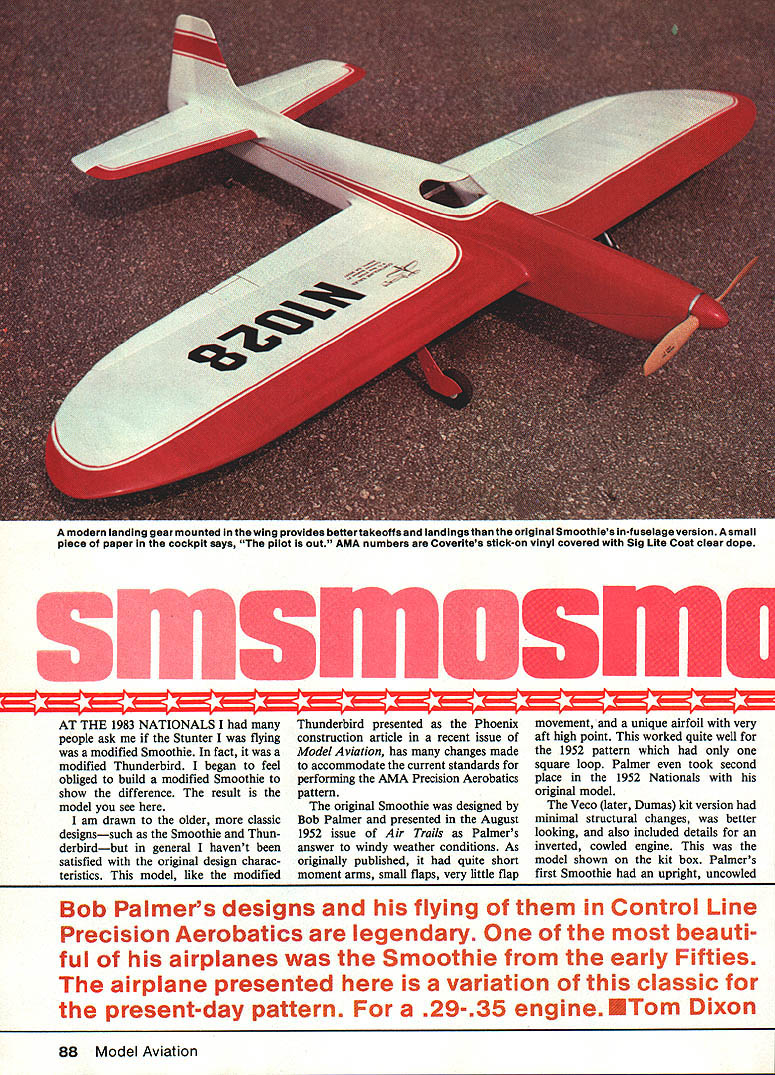
Bob Palmer's designs and his flying of them in Control Line Precision Aerobatics are legendary. One of the most beautiful of his airplanes was the Smoothie from the early fifties. The airplane presented here is a variation of this classic for the present‑day pattern. For a .29–.35 engine. —Tom Dixon
Design goals and major changes
Several factors served as stimuli for reworking the design:
- Confusion: some Smoothies are modified Thunderbirds, and vice versa.
- Desire for a slightly smaller airplane suitable for a Fox .29 engine and Barnstormer/Old‑Timer flying.
- Need for a model easier to handle in very windy conditions—small, lightweight with plenty of power.
- A wish to keep .35‑size airplanes viable amid a trend toward larger, more expensive designs; Control Line Stunt correspondence indicates continued interest in .35‑size planes.
In revamping the Smoothie I wanted a competition‑capable airplane for the present‑day pattern while keeping the appearance of the original. Major changes include:
- Wing: changed to equal‑length panels by extending each outboard panel 2 in., adding about 25 sq. in. of wing area.
- Flaps: larger by moving the hinge line forward and extending flap span one rib bay on each side.
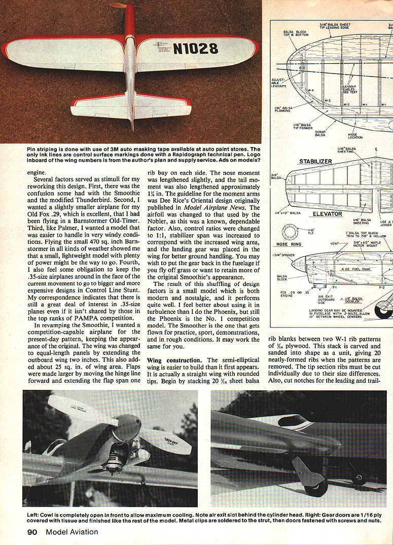
- Moments: nose moment lengthened slightly; tail moment lengthened approximately 1-1/4 in. (guideline for moment arms).
- Airfoil: replaced Dee Rice's Oriental airfoil with the Nobler airfoil, a known dependable choice.
- Controls: control ratios changed (target 1:1 in this design).
- Stabilizer: span increased to correspond with increased wing area.
- Landing gear: placed in the wing for better ground handling; you may prefer to return the gear to the fuselage if you fly off grass or want to retain the original Smoothie's appearance.
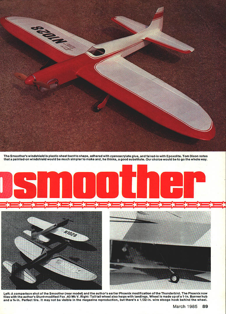
- Windshield: plastic sheet bent to shape, adhered with cyanoacrylate and faired with Epoxolite; a painted‑on windshield is a simpler substitute.
The result of shuffling these factors is a small model that is both modern and nostalgic and performs quite well. I feel better about using it in turbulence. The Phoenix remains the No. 1 competition model; the Smoother is used for practice, sport, demonstrations, and for rough conditions.
Wing construction
The semi‑elliptical wing is easier to build than it first appears—it is actually a straight wing with rounded tips.
- Prepare ribs
- Stack twenty 1/16‑inch sheet balsa rib blanks between two W‑1 rib patterns of 1/16‑inch plywood.
- Carve and sand the stack into shape as a unit to produce twenty neatly formed ribs when the patterns are removed.
- Cut tip section ribs individually due to size differences.
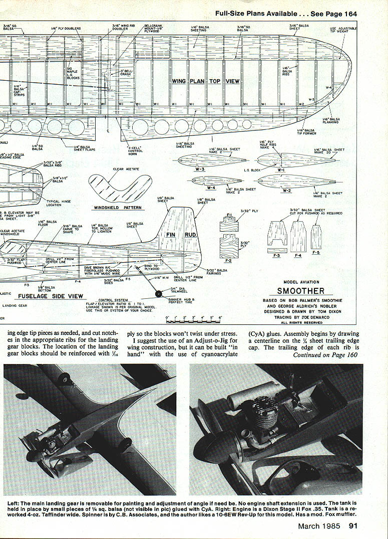
- Cut notches for leading and trailing edge tip pieces as needed, and cut notches in the appropriate ribs for the landing gear blocks.
- Reinforce the landing gear block locations with 1/16‑inch plywood so the blocks won't twist under stress.
- Jigs and assembly
- An Adjust‑o‑Jig is recommended but the wing can be built "in hand" using cyanoacrylate (CyA) glues.
- Draw a centerline on the 1/4‑inch sheet trailing edge cap. Center the trailing edge of each rib on this line at appropriate spacing and tack in place with CyA.
- Add the leading edge strip and align the ribs perpendicular to the spars and cap strips.
- Add tip ribs and tip leading and trailing edge pieces.
- Seat the spars into the tip rib spar notches and glue them.
- Add trailing edge 1/16‑inch sheeting.
- Install controls, landing gear blocks, and leading edge sheeting.
- Sheeting tips and finishing
- Form leading edge sheeting at the compound curve of the tips by soaking the sheeting in hot water before pinning and cementing in place.
- I use Titebond to adhere the leading edge sheeting to ribs and spars and use Sigment at the leading edge so the radius can be more easily sanded.
- Once all glue is dry, check the wing for warps. Steam the wing straight if needed.
- Add center section planking and cap strips.
- Install the tips, tip blocks, lead‑out guide, and wing tip weight box to finish the wing.
Tail surfaces are built from solid sheet balsa, but they should be built up per the plans if very light sheet stock cannot be found.
Fuselage construction
- The fuselage is a basic box with thicker planking on the turtle‑deck area so it can be sanded to a curved shape. This is easier and nearly as light as the usual curved‑shell planking.
- Use slow‑drying epoxy to adhere doublers and engine mounts.
- I find it easiest to build the entire fuselage separate from the wing and tail, with all blocks, cowl, and planking rough‑shaped and temporarily tack‑glued in place.
- Remove the blocks and planking, install the wing and tail, then reinstall the blocks and planking and sand to final shape.
- This avoids carving around the installed wing and tail surfaces.
Alignment
Proper alignment is critical for good performance.
- Set the wing and stabilizer at zero‑zero incidence and parallel with the thrust line.
- Ensure the wing and stabilizer trailing edges are parallel to one another and perpendicular to the centerline of the fuselage when viewed from the top.
- From the frontal view, the wing and stabilizer should be parallel to one another and perpendicular to the fuselage.
- Measure, mark, and "eyeball" alignment carefully before gluing.
Control system
- I use components distributed by X‑Cell (sold by me). The bellcrank is a 3‑in. Top Flight nylon unit.
- Sullivan C‑D cable lead‑outs are used without being bushed at the bellcrank. Instead, lubricate the cable and bellcrank with lithium wheel‑bearing grease to prevent corrosion and wear.
- Soldering cables into bushings, as often done, can weaken the cable; this can lead to breakage due to the corrosive effects of soldering flux. Clean all soldering at lead‑outs and pushrods with a baking soda solution to neutralize any acid.
- As an alternative to cable, you can use 1/8‑in. solid music wire lead‑outs.
- Control horns are drilled to a 1/8‑in. inside diameter at the point shown on the plans; 1/2‑in. length hard brass bushings are soldered in place to prevent wear.
- The elevator horn bushing must be narrower to fit in the tight rear fuselage area.
- The elevator bushing is intentionally drilled out slightly to allow a little play (about 1/16 in. up and down at the trailing edge). This play prevents "hunting" or difficulty in finding a neutral flight attitude that is typical of a newly built flapped Stunter.
- I recommend fiberglass or graphite‑fiber pushrods. They don't require bracing to prevent flex and are lighter than 1/2‑in. music wire.
Finish
- Finish method: Sig dope throughout.
- Base coats on wood with Sig nitrate dope, sanding lightly.
- Apply Sig lightweight Plyspan with nitrate dope as adhesive. Seal the tissue with two coats of nitrate dope.
- Apply a filler made of Sig Lite‑Coat evaporative dope mixed with talcum powder. Wet‑sand with 400‑grit paper, then spray color coats.
- I switched back to dope to obtain a completely fuel‑proof finish.
- To get a shine equivalent to polyurethane, the dope finish must be polished:
- Roughen the surface uniformly with a sponge and an abrasive cleaner (Ajax) mixed with water to form a thick paste. This creates a uniform dull sheen.
- Use DuPont No. 7 white polishing compound with a soft rag or cheesecloth and polish by hand.
- Finish with an automotive paste wax.
- Note: I strongly disapprove of Imron and other urethane paints—their extreme toxicity makes them hazardous for our use.
Windshield
- The Smoother's windshield is made from plastic sheet bent to shape, adhered with cyanoacrylate glue, and faired in with Epoxolite.
- A painted‑on windshield is a simpler and acceptable substitute; choosing full formed plastic is a matter of preference.
Power, props, and flight notes
- Engines: a stock Fox .29 or .35 is plenty of power. O.S. .30 or .35 engines will also work.
- Propeller: a 10×6 wide‑blade prop or a cut‑down 11×5 should give good performance.
- Lines: 58 to 63 feet; typical lap time is in the 5.0 to 5.5‑second range.
- Safety: pull‑test the model and control lines before the first flight and before each subsequent flight. Use a muffler and fly safely.
Transcribed from original scans by AI. Minor OCR errors may remain.

