
Snapdragon
Kin Cartrette
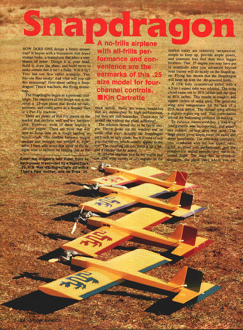
A no-frills airplane with all-frills performance and convenience are the earmarks of this .25-size model for four-channel controls.
How does one design a better mousetrap? It begins with a brainstorm, design it in your head, build it, draw the plans, and build more to make certain it isn't a fluke. Will it fly? Yes — this one flies nicely. What will you call this mousetrap? Snapdragon.
The Snapdragon began as a personal challenge: to develop a .25-size plane that would be fully aerobatic and could serve as a Sunday flier or a Fun Fly machine. Many Fun Fly designs require .40-size engines or sacrifice strength for lightness; some balloon on landing because of thick airfoils. The Snapdragon aims to avoid those problems while remaining affordable, compact, and aerobatic.
Design highlights:
- 15% fully symmetrical airfoil
- Aspect ratio: 4.5:1
- Wing chord: 10-1/4 in.
- Span: 45-1/2 in.
- Wing area: ~466 sq. in.
- Mid-wing configuration, no dihedral
- Generous control surfaces and long chord for radio/servo space
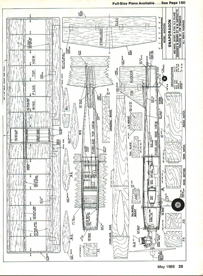
- D-tube wing construction with trailing-edge sheeting and squared-off tips
- Box-style fuselage for simplicity and strength
- Taildragger gear (no nosewheel) with wide stance
The thin, symmetrical airfoil and generous wing area reduce ballooning on landing and permit higher top speed and stable inverted flight. Large ailerons and the mid-wing/low aspect ratio give excellent roll performance. All moments are kept reasonably short to enable crisp, hot performance when desired.
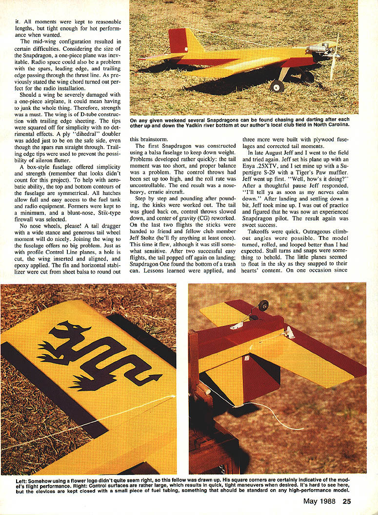
Early prototypes taught lessons: an all-balsa fuselage produced too-short tail moment, excessive control throws, uncontrollable roll rate, and a nose‑heavy, erratic aircraft. Repairs and redesigns (notably switching to plywood fuselages and correcting tail moments) produced a well-behaved, highly capable sport ship.
Engines tested and recommended:
- Enya .25 XTV — excellent balance and power
- O.S. Max .25 FP — solid performer
- Supertigre S-29 — faster but slightly heavier; requires ~1 oz. tail weight and an extra downthrust washer
- A .40-size engine is too much for this airframe
- May try Enya .19TV to explore lower-power limits
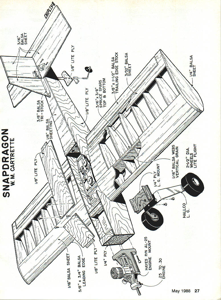
Ground handling is excellent: a wide main gear stance and generous tailwheel moment give straight takeoff and landing rolls and good crosswind behavior. Prop clearance is ample for 9-in. props; few props have been broken in testing.
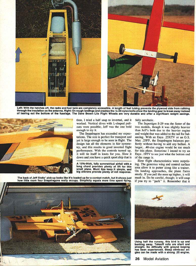
For rough landings and crashes, 1/4-20 nylon bolts are used for the landing gear so they shear away instead of ripping out the fuselage. Dave Brown Lite Flight wheels (2-1/2 in. diameter) are light and durable.
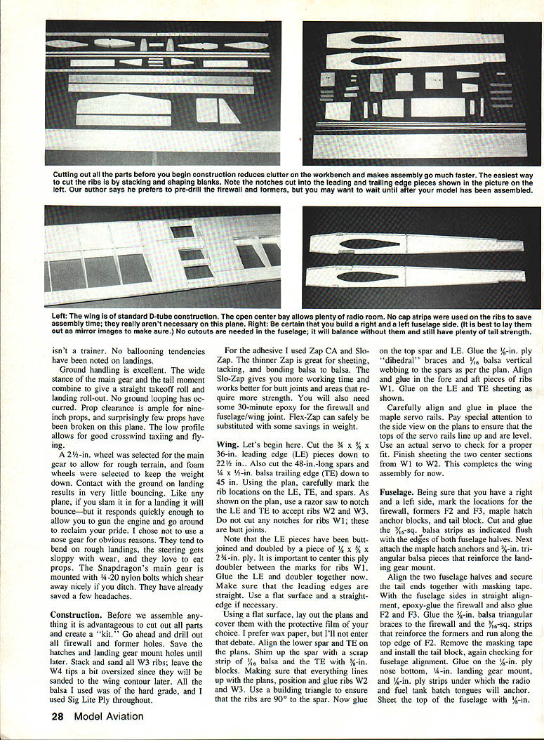
Construction
Before assembly, cut out all parts and create a kit. Drill firewall and former holes, but save hatch and landing gear mounting holes until later. Stack and sand all W3 ribs; leave W4 ribs slightly oversized to sand to the wing contour later. Use hard-grade balsa and Sig Lite Ply where indicated.
Adhesives:
- Zap CA (thin) — great for sheeting, tacking, and balsa-to-balsa bonds
- Slo-Zap — more working time for butt joints and stronger areas
- 30-minute epoxy — firewall and fuselage/wing joint
- Flex-Zap may substitute for weight savings
Wing
- Cut parts:
- Cut the 3/4 x 3/8 x 36-in. leading edge pieces down to 22-1/2 in.
- Cut 48-in. spars and 3/4 x 1/2-in. balsa trailing edge stock down to 45 in.
- Mark rib locations on LE, TE, and spars per plan.
- Notch the LE and TE to accept ribs W2 and W3 with a razor saw. Do not notch for W1 (butt joints).
- Butt-joint and double the LE pieces with a 1/2 x 5/8 x 2-3/4-in. ply doubler; center the doubler between marks for W1. Ensure leading edges are straight.
- On a flat building surface covered with protective film (wax paper or similar), align lower spar and TE on the plans. Use scrap 1/16-in. balsa and 3/16-in. blocks to set heights.
- Glue ribs W2 and W3 in place; use a building triangle for 90° to the spar. Glue top spar and LE.
- Glue 1/8-in. ply "dihedral" braces and 1/16-in. balsa vertical webbing to spars as per plan. Align and glue fore and aft pieces of ribs W1. Glue on LE and TE sheeting.
- Glue in maple servo rails; check alignment and level with an actual servo. Finish sheeting the center sections from W1 to W2.
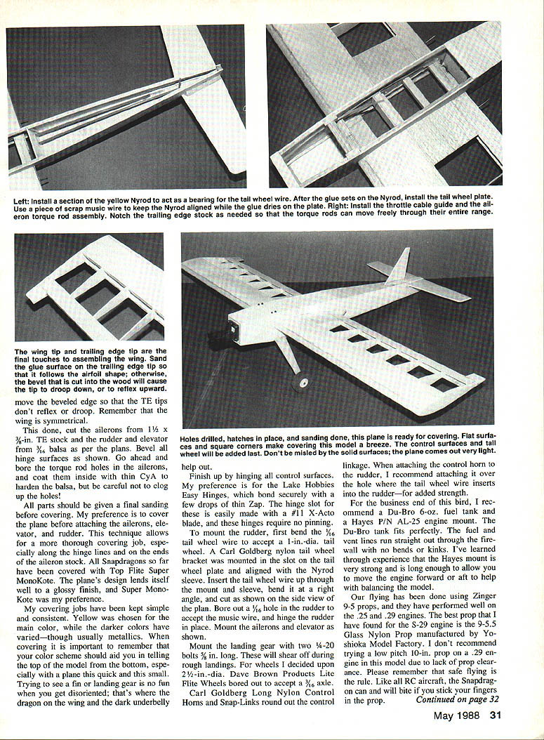
- Add 1/8-in. W4 balsa tips and TE tips cut from 1/2 x 3/8-in. TE stock. Reshape and sand to blend with wing contours.
- Cut ailerons from 1-1/4 x 3/16-in. TE stock. Bore torque rod holes and coat inside with thin CyA to harden the balsa (avoid clogging holes).
Notes:
- Use a D-tube construction with trailing-edge sheeting. Square tips simplify construction and do not harm performance.
- A ply dihedral doubler is added for safety despite straight-through spars.
- Square trailing-edge tips help prevent aileron flutter.
- Wrap fiberglass around the longer left brass tubing and the TE torque-rod area, coat with thin CyA for added strength.
Fuselage
- Identify right and left fuselage sides. Mark locations for firewall, formers F2 and F3, maple hatch anchor blocks, and tail block.
- Glue 1/16-in. sq. balsa strips as indicated. Glue triangular balsa pieces reinforcing the landing gear mount.
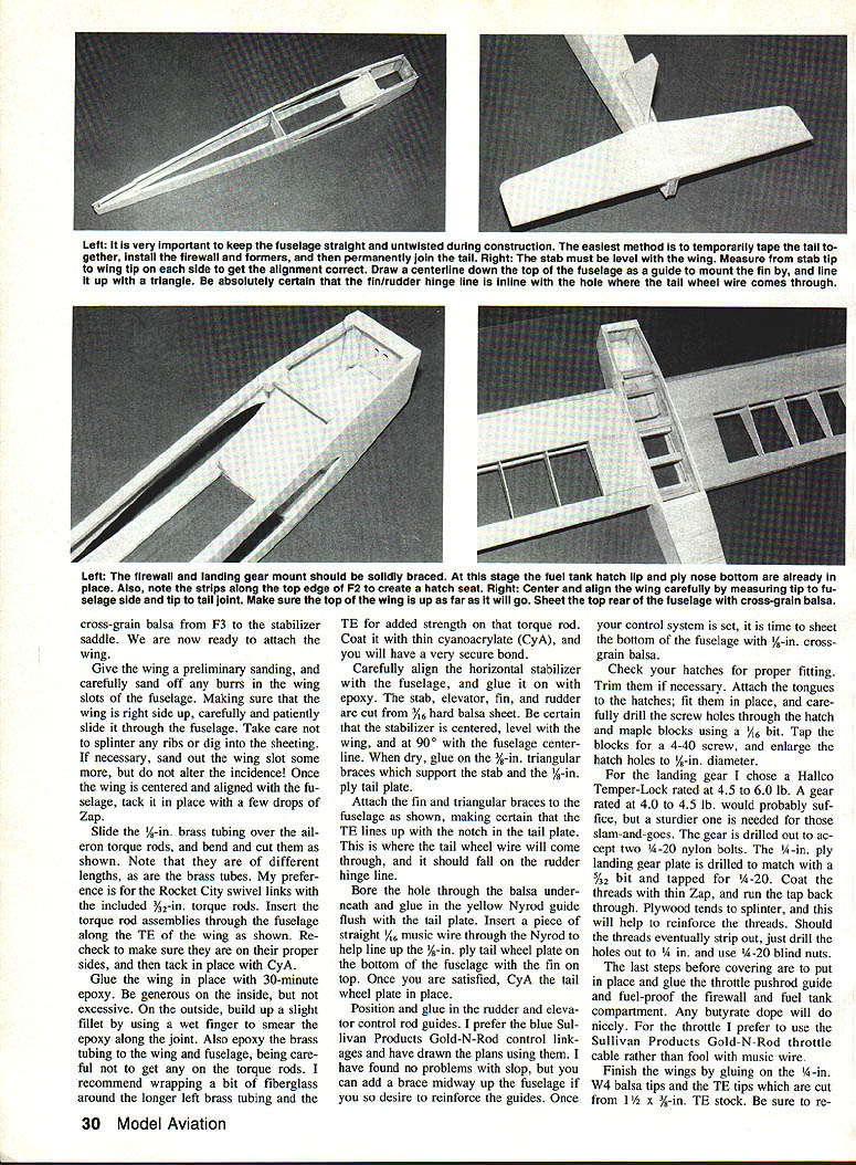
- Align fuselage halves and secure tail ends with masking tape. With sides straight, epoxy-glue firewall and glue F2 and F3. Glue 3/8-in. balsa triangular braces to firewall and 1/16-in. strips reinforcing formers along the top edge of F2.
- Remove masking tape and install tail block, checking alignment. Glue 1/8-in. ply nose bottom, 1/4-in. landing gear mount, and 1/8-in. ply strips under which hatch tongues will anchor. Sheet the top with 1/8-in. balsa.
- Cross-grain sheet the bottom from F3 to the stabilizer saddle.
- Slide the wing through the fuselage: sand wing slot burrs carefully, then slide the wing (right side up) into place. Tack with a few drops of Zap to hold.
- Install aileron torque rods and brass tubing: slide 1/8-in. brass tubing over torque rods, bend and cut as shown on plan. Use Rocket City swivel links and 3/32-in. torque rods if preferred. Insert assemblies along the TE of the wing and tack with CyA. Ensure proper side placement.
- Glue wing in place with 30-minute epoxy. Apply epoxy generously inside the joint; on the outside, build a slight fillet with a wet finger. Epoxy the brass tubing to wing and fuselage, avoiding torque rods. Wrap fiberglass and CyA on the longer left tube area for strength.
- Align and epoxy the horizontal stabilizer; ensure it is centered, level with the wing, and at 90° to the fuselage centerline. Glue 3/8-in. triangular braces and the 1/2-in. tail plate when dry.
- Attach fin and triangular braces; make sure TE lines up with the notch in the tail plate where the tailwheel wire passes through (on the rudder hinge line).
- Bore hole under the tail plate and glue in a yellow Nyrod guide flush with the tail plate. Insert 1/16-in. music wire through the Nyrod to align the 1/8-in. ply tailwheel plate, then CyA the tailwheel plate in place.
- Position and glue rudder and elevator control rod guides (Sullivan Gold-N-Rod recommended). Add a mid-fuselage brace if desired for reinforcement.
- Sheet the bottom with 1/8-in. cross-grain balsa.
- Fit hatches: trim as necessary, attach tongues, drill screw holes through hatch and maple blocks with a 1/16-in. bit, tap blocks for 4-40 screws, and enlarge hatch holes to 1/8-in. diameter.
Landing gear:
- Recommended Hallco Temper-Lock rated 4.5–6.0 lb (4.0–4.5 lb may suffice). Drill gear for two 1/4-20 nylon bolts.
- 3/32-in. ply landing gear plate is drilled and tapped for 4-20; coat threads with thin Zap and run the tap back through to reinforce. If threads strip later, enlarge to 1/4-in. and use 1/4-20 blind nuts.
- Mount gear with two 1/4-20 bolts, 3/8 in. long (shear in rough landings).
- Wheels: 2-1/2 in. Dave Brown Lite Flight Wheels bored for 3/16-in. axle.
Final pre-cover steps:
- Install and glue throttle pushrod guide. Use Sullivan Gold-N-Rod throttle cable preferred over music wire.
- Fuel-proof firewall and fuel tank compartment with butyrate dope.
- Finish sand all parts before covering.
Covering and finish:
- Cover before attaching ailerons, elevator, and rudder for better hinge-line coverage.
- Top Flite Super MonoKote recommended. Simple, glossy color schemes work well (e.g., yellow top, darker/metallic bottom for orientation).
- Use Lake Hobbies Easy Hinges bonded with thin Zap; hinge slots can be cut with a #11 X-Acto blade (no pinning required).
- Install rudder: bend 1/16-in. tailwheel wire for a 1-in. diameter tailwheel, use Carl Goldberg nylon tail-wheel bracket, run wire through mount and Nyrod sleeve, bend, and thread into rudder. Bore 1/16-in. hole in rudder for wire and hinge rudder in place.
- Mount ailerons and elevator as per plan. Use Carl Goldberg Long Nylon Control Horns and Snap-Links; mount rudder control horn over hole where tailwheel wire enters rudder for added strength.
Recommended engine/prop/tank/mount:
- Du-Bro 6-oz. fuel tank
- Hayes P/N AL-25 engine mount (strong and long for CG adjustments)
- Props: Zinger 9.5x5 or Yoskisha 9.5x5 glass nylon for S-29. Avoid low-pitch 11-in. props on .29 engines for lack of top end.
- Use Zinger 9.5x5 props on .25 and .29 engines with good results.
Radio and installation:
- Futaba Conquest 4NL and Airtronics SR4R have been used successfully.
- Offset elevator and rudder servos slightly to prevent pushrod crowding.
- Mount on-off switch and charging jack on fuselage side opposite engine exhaust in the receiver/battery area.
- Route receiver antenna outside the fuselage away from engine exhaust; attach to fin and use a rubber band as a shock cord.
- Wrap receiver and battery in foam rubber to prevent vibration/impact damage; enclose in plastic wrap to protect from fuel leaks.
Control throws (initial and current):
- Initial recommended for first flight:
- Ailerons: 1/4 in. each way
- Rudder: 1 in.
- Elevator: 3/8 in.
- Current flying setup (hot but controllable):
- Rudder: ~1-1/8 in.
- Elevator: 1/2 in.
- Ailerons: 3/8 in.
- If throws are too hot, the plane can get away from you — start conservative and increase as comfortable.
Plan labels (as shown on plan drawings):
- Wing — plan — top view
- Stabilizer
- Elevator (ELEV)
- Fuselage top view
- Fuselage side view
- Fin
- Rudder
- Tail plate
- Tailwheel mount
- L.G. mount
- Fuselage side
- Radio hatch
- Tank hatch
- Nose bottom
Flight
The Snapdragon flies as intended: quick takeoffs, outrageous climb angles, crisp turns, rolls, and loops. Stall turns and snaps are impressive — the model seems to float then snap to attention. The long chord, 15% symmetrical airfoil, and large control surfaces enable both slow, stable flight and full aerobatics with the controls cranked up.
Handling notes:
- Slow-flight: generous wing and control area allow puttering like a trainer; flares nicely on approach. Pulling nose up too high will mush in; be careful to avoid attempting to "park" it — it will snap.
- Aerobatics: half snaps to inverted work; vertical dives with L-shaped pullouts are possible. With hot control throws, it will "tie itself in knots" — reduce throws if you need more predictability.
- Ground handling: wide main gear and tail moment prevent ground looping. Low profile and adequate prop clearance help with crosswind taxiing.
Performance comparisons:
- Supertigre S-29: faster, slightly heavier; requires small tail weight and extra downthrust.
- Enya .25 XTV: excellent balance and performance; no ballast usually required.
- O.S. Max .25 FP: solid, though slightly less power than Enya in observed tests.
Durability and practical details:
- 1/4-20 nylon bolts for gear shear to save fuselage damage.
- Dave Brown Lite Flight Wheels are durable and light.
- Fuel tubing length and routing prevent rubbing through plywood side.
- Small piece of fuel tubing as a hatch seal is standard on high-performance models.
Final Assembly and Tips
- Sand glue surfaces on TE tips so they follow the airfoil; remove any beveled edge that causes reflex or droop.
- Be careful when hardening aileron/hinge holes with CyA — do not clog holes.
- Covering: choose top/bottom colors that aid orientation; consider a distinctive wing dragon or dark underbelly for quick top/bottom identification.
- Receiver and battery mounting: foam-wrapped, plastic-covered, and secured away from exhaust.
- Safety: "Like all RC aircraft, the Snapdragon can and will bite if you stick your fingers in the prop."
Acknowledgments
Special thanks to:
- Charles Downing — aerodynamic and structural advice, encouragement to write this article
- Patrick O'Connell — ideas incorporated into the design
- Jeff Stoltz — test pilot and development partner; put the plane through its paces
- RAMS RC club members in the Winston-Salem/King area of North Carolina for support and patience during early trials
SAFE FLYING IS NO ACCIDENT
Transcribed from original scans by AI. Minor OCR errors may remain.

