
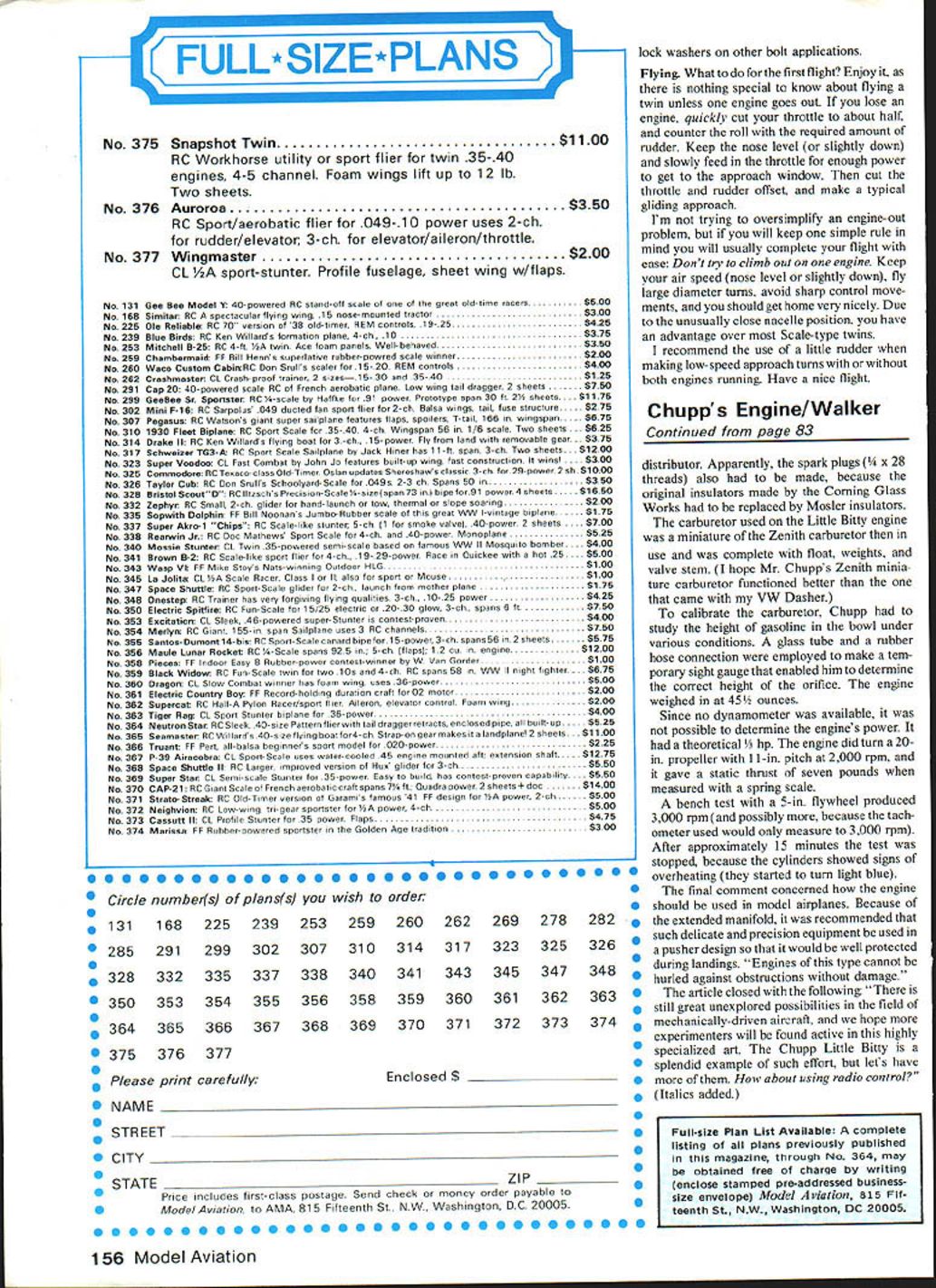
Snapshot Twin
Luther Hux
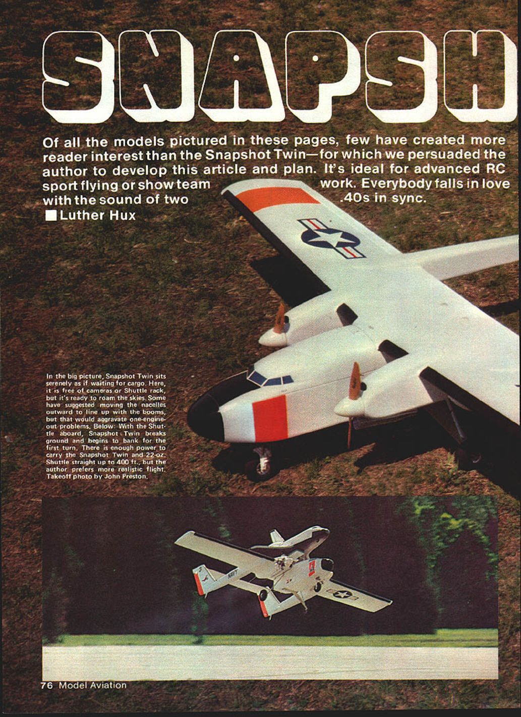
Of all the models pictured in these pages, few have created more reader interest than the Snapshot Twin — for which I was persuaded to develop this article and plan. It's ideal for advanced RC sport flying or show-team work. Everybody falls in love with the sound of two H.P. .40s in sync.
Some of you are probably curious about an unusual name like Snapshot Twin. Those familiar with the Project Snapshot articles (MA, June 1979 and June 1980) know exactly where the twin and its name came from.
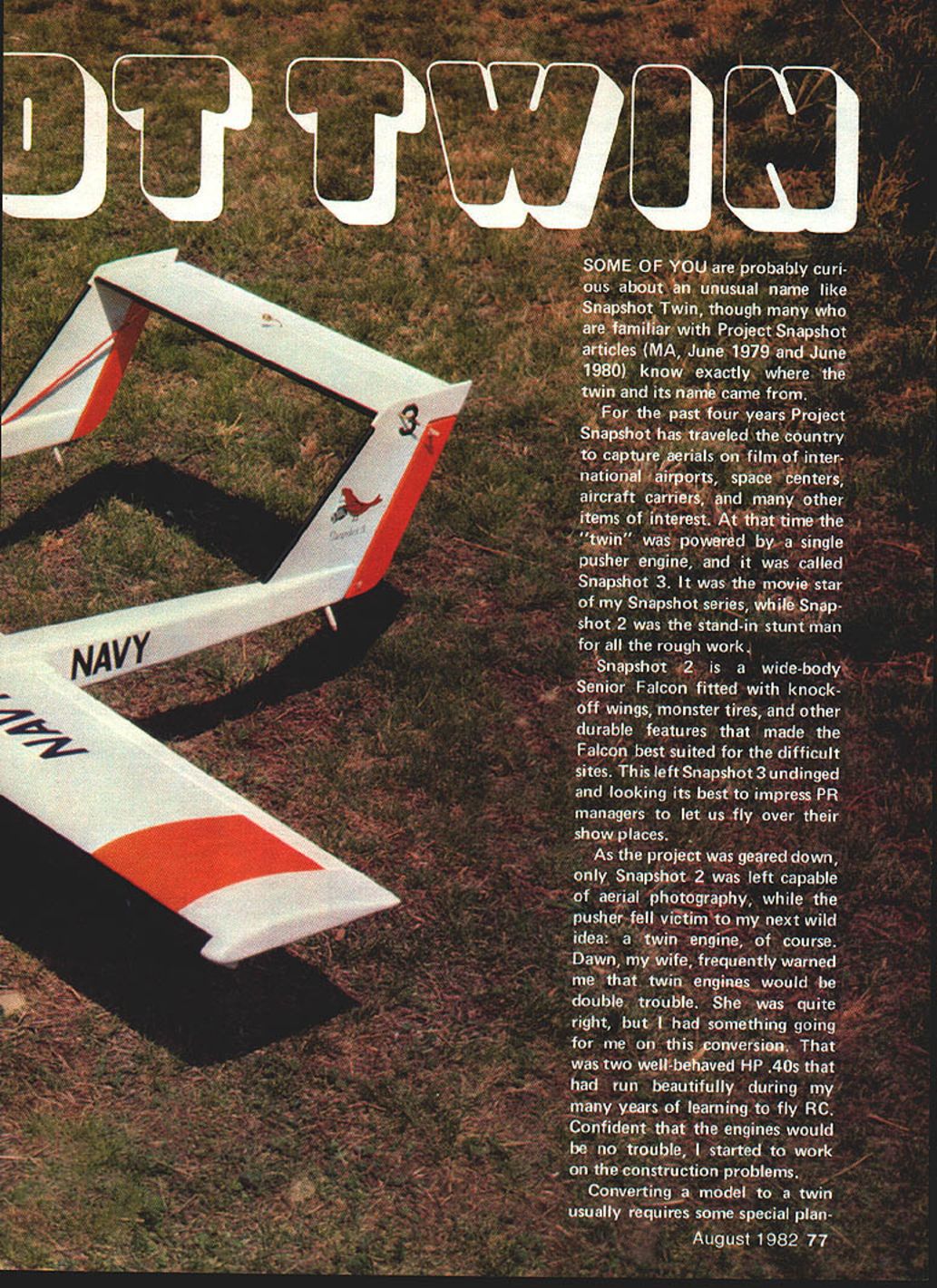
For four years Project Snapshot traveled the country to capture aerials on film of international airports, space centers, aircraft carriers, and many other items of interest. At that time the "twin" was powered by a single pusher engine and was called Snapshot 3. It was the movie star of my Snapshot series, while Snapshot 2 was the stand-in stunt man for all the rough work.
Snapshot 2 is a wide-body Senior Falcon fitted with knockoff wings, monster tires, and other durable features that made the Falcon best suited for the difficult sites. This left Snapshot 3 undamaged and looking its best to impress PR managers so we could fly over their show places.
As the project was scaled down, only Snapshot 2 remained capable of aerial photography, while the pusher fell victim to my next wild idea: a twin engine, of course. Dawn, my wife, frequently warned me that twin engines would be double trouble. She was quite right, but I had something going for me on this conversion: two well-behaved H.P. .40s that had run beautifully during my many years of learning to fly RC. Confident the engines would be no trouble, I started to work on the construction problems.
Converting a model to a twin usually requires special planning in wing construction to support the vibrating power plants. It was suggested that converting an already-completed foam-core wing was unwise, but since the wing had to handle the stresses of the tail booms and tail surfaces, there seemed to be adequate spars for handling the engine nacelles as well. The method used for installing the nacelle bulkheads creates very little interruption in the bottom wing skin, so there is little loss in surface strength.
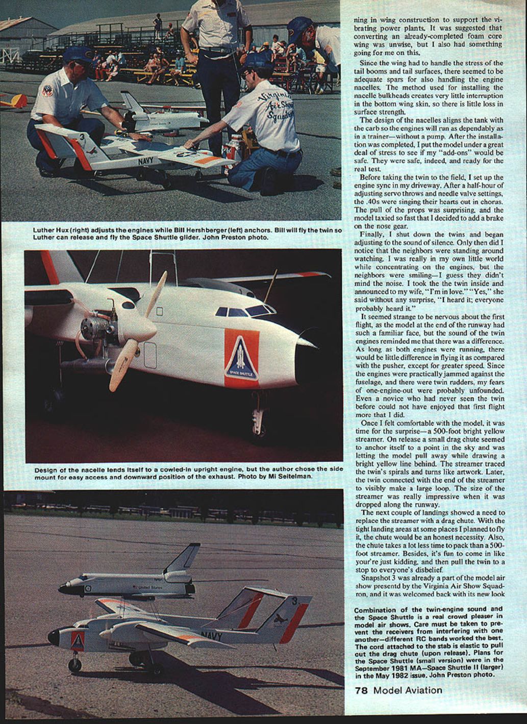
The nacelle design aligns the tank with the carb so the engines will run as dependably as in a trainer—without a pump. After installation was completed I put the model under a great deal of stress to see if the add-ons would be safe. They were safe indeed and ready for the real test.
Before taking the twin to the field I set up and synchronized the engines in my driveway. After a half-hour of adjusting servo throws and needle-valve settings the .40s were singing their hearts out in chorus. The pull of the props was surprising, and the model taxied so fast that I decided to add a brake to the nose gear.
Finally I shut down the twins and began adjusting to the sound of silence. Only then did I notice the neighbors standing around watching. I was really in my own little world while concentrating on the engines, but the neighbors were smiling — I guess they didn't mind the noise. I took the twin inside and announced to my wife, "I'm in love." "Yes," she said without surprise, "I heard it; everyone probably heard it."
It seemed strange to be nervous about the first flight, as the model at the end of the runway had such a familiar face, but the sound of the twin engines reminded me that there was a difference. As long as both engines were running there would be little difference in flying it compared with the pusher, except for greater speed. Since the engines were practically jammed against the fuselage and there were twin rudders, my fears of a one-engine-out were probably unfounded. Even a novice who had never seen the twin before could not have enjoyed that first flight more than I did.
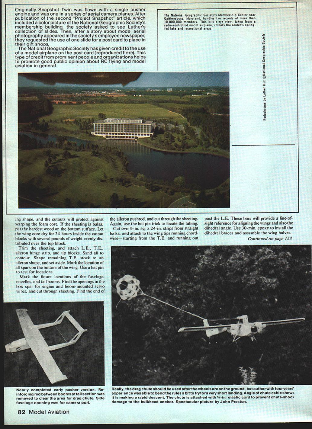
Once I felt comfortable with the model, I released a 500-foot bright-yellow streamer. On release a small drag-chute effect seemed to anchor itself at a point in the sky while letting the model pull away and drawing a bright yellow line behind. The streamer traced the twin's spirals and turns like artwork. Later, the twin connected with the end of the streamer and made a large visible loop. The streamer was impressive when dropped along the runway.
Subsequent landings showed the need to replace the streamer with a drag chute for tight landing areas. A chute is a necessity at some sites, takes far less time to pack than a 500-foot streamer, and makes for a great show: come in like you're just kidding, then stop the twin to everyone's disbelief.
Snapshot 3 (the converted twin) became part of the Virginia Air Show Squadron's program and was welcomed back with its new look. The combination of twin-engine sound and a Space Shuttle model is a real crowd pleaser in model air shows. Take care to prevent receiver interference — different RC bands worked best for me. The cord attached to the stab is elastic to pull out the drag chute on release. Plans for the small Space Shuttle were in the September 1981 MA; Space Shuttle II (larger) was in the May 1982 issue.
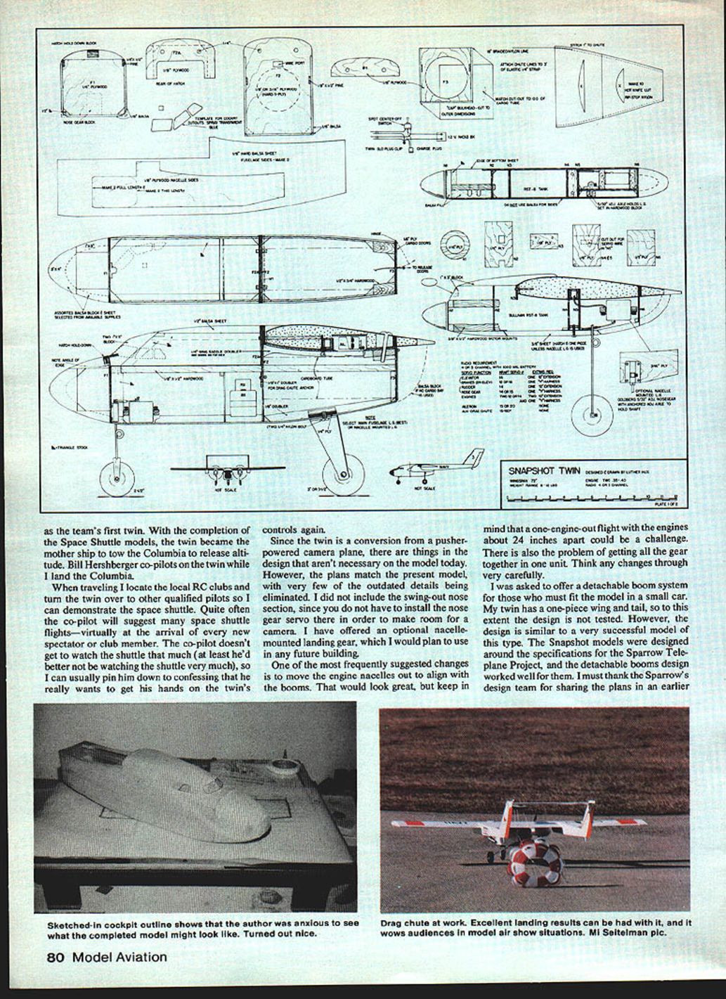
One frequently suggested change is to move the engine nacelles out to align with the booms — that would look great, but a one-engine-out flight with the engines about 24 inches apart could be a challenge. There is also the problem of getting all the gear together in one unit. Think any changes through very carefully.
I was asked about a detachable-boom system for those who must fit the model in a small car. My twin has a one-piece wing and tail, so the detachable-boom design is untested on my model. However, the design is similar to a very successful model of this type. The Snapshot models were designed around the specifications for the Sparrow Teleplane Project, and the detachable-booms design worked well for them. I thank the Sparrow design team for sharing their plans.
Construction
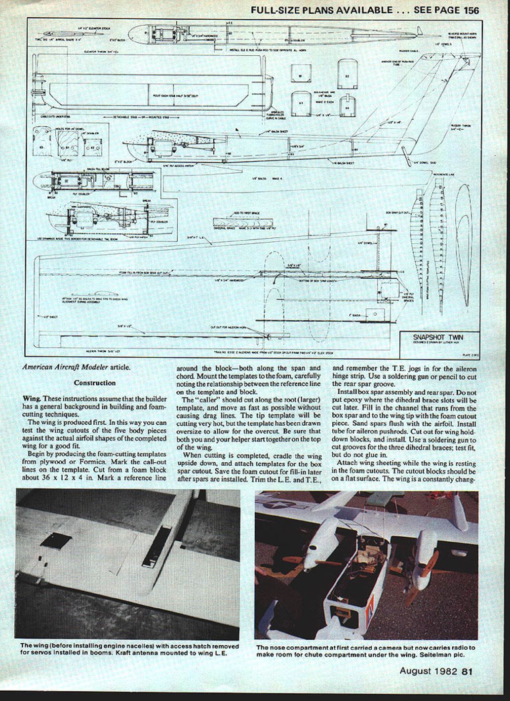
These instructions assume the builder has a general background in building and foam-cutting techniques. The wing is produced first so you can test the wing cutouts of the five body pieces against the actual airfoil shapes of the completed wing for a good fit.
Wing
- Produce foam-cutting templates from plywood or Formica. Mark the call-out lines on the templates.
- Cut from a foam block about 36 x 12 x 4 in. Mark a reference line around the block — both along the span and chord.
- Mount the templates to the foam, carefully noting the relationship between the template reference line and the block.
- The cutter should cut along the root (larger) template, moving as fast as possible without causing drag lines. The tip template will be cutting very hot; the template is drawn oversize to allow for overcut. Be sure both cutter and helper start together on the top of the wing.
- When cutting is completed, cradle the wing upside down and attach templates for the box-spar cutout. Save the foam cutout for fill-in later after spars are installed.
- Trim the L.E. and T.E.; remember the T.E. jogs in for the aileron hinge strip. Use a soldering gun or pencil to cut the rear spar groove.
- Install box-spar assembly and rear spar. Do not put epoxy where the dihedral-brace slots will be cut later.
- Fill the channel that runs from the box spar to the wing tip with the foam cutout piece. Sand spars flush with the airfoil.
- Install tube for aileron pushrods. Cut out for wing hold-down blocks and install.
- Use a soldering gun to cut grooves for the three dihedral braces; test fit but do not glue them in yet.
- Attach wing sheeting while the wing rests on the foam cutouts. The cutout blocks should be on a flat surface to support the changing airfoil and prevent warping.
- If the sheeting is balsa, put the hardest wood on the bottom surface.
- Let the wing core dry for 24 hours inside the cutout blocks with several pounds of weight evenly distributed over the top block.
- Trim the sheeting and attach L.E., T.E., aileron hinge strip, and tip blocks. Sand all to contour.
- Shape remaining T.E. stock to an aileron shape and set aside. Mark the location of all spars on the bottom of the wing. Use a hat pin to test locations.
- Mark future locations of the fuselage, nacelles, and tail booms. Find openings in the box spar for engine and boom-mounted servo wires and cut through sheeting. Use the hat-pin trick to locate the aileron pushrod tubing.
- Cut two 1/2-in. sq. x 24-in. strips from straight balsa and attach to the wing tips running chordwise — starting from the T.E. and running out past the L.E. These bars provide a line-of-sight reference for aligning the wings and dihedral angle.
- Sight down the two balsa strips and align the wing tips regardless of how the center section aligns. Set the center on waxed paper while epoxy sets and check alignment often.
- Fill any variations in the center section with epoxy, but do not use any cloth on the top of the wing — only on the bottom. You may raise the dihedral angle to 3/4 in. per tip if you wish.
- Install the wood for the aileron servo tray. Do not attach the L.E. bulkhead or wing dowels until later. Install complete aileron linkages in the boom area.
Fuselage
- Check the wing saddle on the side template to see if any adjustments are necessary. Cut sides and bulkheads from the specified stock. Note that the center bulkhead is 1/8-in. hard birch plywood but could be cut from thicker stock.
- Epoxy hardwood longerons to fuselage sides. Assemble the sides and the first two bulkheads; the rear bulkhead is attached last (it caps the fuselage and does not fit between the fuselage sides).
- Sheet the bottom. Install hardwood wing hold-down blocks. Fill corners with triangular stock.
- Assemble balsa blocks and sheets for the nose section and cockpit hatch. Cut the top and side profiles with a band saw. Angle the front edge of the hatch so it can be raised and pulled forward when the rear plywood bulkhead is fitted on the wing dowels.
- Tack-glue the nose and hatch in place for shaping. Cut and sand until you like the shape — a belt sander works well. If you sand through, install another balsa block inside to fill it.
- Be careful not to oversand the 1/8-in. sides and bottom; too much sanding will leave only triangular stock holding the nose-gear bulkhead. When content with the shape, remove blocks and rout the inside to about 1/4-in. thickness.
- For a cargo tube, use a cardboard tube (for example from a roll of wrapping paper). Line the inside with contact paper and glue the tube in place. Install doors and release device. If no cargo tube is used, move radio gear under the wings, cap the rear bulkhead with balsa, and sand to shape.
- If you decide on a fuselage-mounted main landing gear (strongest), mount the 1/8-in. plywood plate and side doublers at the bottom of the fuselage. Drill and tap for two 1/4-20 nylon bolts to hold the aluminum landing gear.
- Flatten the center leading edge of the wing to match the width of the center bulkhead. Temporarily set the wing saddle foam in place and set the wing with the W-1 bulkhead in place, matched with the center fuselage bulkhead.
- Clamp or weight the wing in position. Double-check wing and saddle match; shim or cut any differences. Put epoxy between the W-1 bulkhead and the wing leading edge.
- Mark dowel positions on the fuselage center bulkhead and drill through bulkheads and wing up to the box-spar tab. Then drill holes for the hold-down bolts at the rear of the wing using a drill that matches the bolt threads.
- Remove the wing. Tap the 1/4-20 holes for the wing hold-down nylon bolts. Drill out the holes in the wing for bolts to fit through and coat lightly with epoxy.
- Install 1/8-in. dowels in the wing leading edge. Place cockpit hatch and drill 1/4-in. holes to match the center bulkhead. Test dowel fit and bulkhead alignment. Fill the leading-edge gap with balsa scrap and sand to match the top of the fuselage. Install a hold-down bolt in front of the hatch.
Booms and Rudders
- Choose between permanently mounted booms or detachable ones and locate correct bulkheads and construction details. Then choose between a detachable stab or a one-piece boom-and-stab assembly. The one-piece removable boom assembly is easiest of the removable choices.
- To protect the stab/rudder joints from damage, use a 28-in. span bar bolted between the booms to prevent them from being forced out of alignment while being transported.
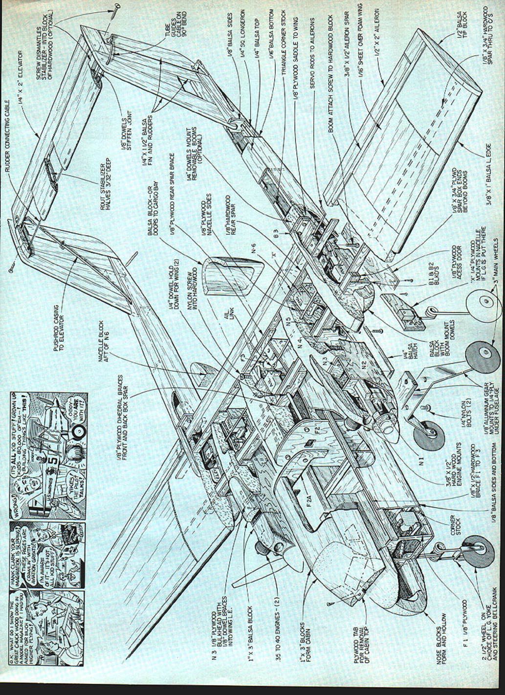
- In the plans, the left side shows the detachable stabilizer method with the cross linkage between the rudders ending between the two rudders — necessary if you choose to remove the stab. The permanently mounted stab (right side) has the rudder cross linkage outside the rudders for easier installation and adjustment.
- Be sure to use the same inside-or-outside system on both rudders, or you will end up with a dive brake instead of rudder control.
- Cut all pieces for the booms and rudders. Assemble the rudder pieces first. Frame the booms upside down over the plans (tops flat). Turn booms over and install fins. Hold booms squarely on a flat surface and test fins for vertical alignment.
- Cap tops of booms with 1/64-in. sheet cut to outline. Do not enclose the bottoms until later.
- Weight booms down on a flat surface and check they are parallel and squarely aligned. Test fit the wing and make necessary adjustments in boom saddles until the wing fits correctly. Epoxy wing in place. For removable booms, epoxy only the bulkhead and hardwood pieces that remain on the wing.
- Cut nose blocks to general shape, epoxy in place, and sand to final shape. Install elevator and rudder servo rails and servos. Route the pushrods through the bulkheads. The elevator uses a simple direct pushrod system that requires an offset control horn to adjust for the different angle of approach.
- Frame the area around the servo for a servo hatch. Cut the hatch from 1/16-in. plywood and hinge or screw in place. Sheet the bottoms of the booms. Sand and shape overall.
Stabilizer
- Check the exact distance between the fins and cut the stabilizer pieces to length from Sig airfoil-shaped balsa stock.
- Rout the insides to lighten and cut the rudder cross-tie channel. Glue the two halves together.
- Epoxy the stabilizer to the top of the fins, checking the angle carefully. Mark the outline of the stab on the outside of the fins and locate/drill for the rudder cross-tie channel.
- Drill three more holes for 3/16-in. dowels to strengthen the joint. Sand dowels flush with the surface.
- Do not install the rudder cable in the channel until after the model is covered.
Nacelles
- I did mine some three years after the original build; you can leave these for later if you wish.
- Check spacing of the motor mounts against your engines and adjust if needed. Slot the sheeting and foam around the spars for the nacelle bulkheads.
- Cut all required pieces; note that the sides are made of Lite Ply — do not use balsa here.
- Test side templates for fit with your wing. Fit bulkheads in the wing slots and hold sides in place on the wing. Mark the bulkhead positions on the side pieces. Remove from wing and assemble nacelles with epoxy.
- Cut hole for servo cable in box spar. Epoxy nacelles to the wing. Cut general shape in balsa blocks for the top and rear of nacelles and epoxy in place.
- Tack-glue the bottom sheet in place and shape the entire nacelle. Remove the bottom sheet and cut out the hatch area. Epoxy the front bottom portion in place.
- If using optional nacelle-mounted landing gear, cut the plywood mounting plate and epoxy in place. The hatch will need to be made in two pieces and broken around the L.G. shaft. Strap a handmade L.G. wire to the plywood, or use the stock L.G. shown on the plans.
- Hinge or bolt the hatch(s) in place. The access hatches may be small with access only to the servo. Fuel-proof the engine compartment and install engine, tank, and servo. Route the pushrod along the bottom after installing the tank.
- With the main (or nacelle) L.G. installed, you can now install the shortened nose gear. Adjust the nose gear so the model is level or slightly nose down. The nacelle main gear will require the shortest nose gear.
Radio Installation
- Attach extension cables to wing-mounted servos. Tape together any connectors that will be inside the box spar.
- On removable-boom installations, connectors must stay in the booms so they can be disconnected. A longer extension will be required.
- Pull cables through the box spar by snaking a small stiff wire from the center to the end of the box spar. Tape the connector to the wire and pull the cable through gently.
- Do the booms first, then the engines. Mark the connectors for easy field assembly — there are too many cables to easily remember the correct order.
Miscellaneous
- Coat the model with Balsarite to aid covering the many compound curves. My model is covered entirely with white Permagloss Coverite. The leading edges of all flying surfaces are trimmed with black Contact-brand shelf covering.
- Install control surfaces with plenty of wire pivot hinges. Too few hinges (or the wrong type) will not survive on a fast model like this one.
- Complete the rudder cross-tie by locating the channel in the stabilizer through the covering. Install small flexible tubing and cable through the channel. Epoxy a piece of annealed (flexible) brass tubing at each end of the stab.
- Place a rounded object against the fin and bend the tubing until it aligns with the rudder control horn. Finish the cables with threaded ends and clevises.
- The antenna can be installed inside the wing during construction if the antenna is detachable. Otherwise route the antenna out of the booms and then to the tail. Keep the antenna away from the box spar — there are servo cables inside.
- Complete engine tests and adjustments before going to the field if possible.
- Take precautions against twin-engine vibration problems:
- Apply a dab of silicone glue over servo arm screws.
- Use lock washers on other bolt applications.
Flying
- What to do for the first flight? Enjoy it. There is nothing special to know about flying this twin unless one engine fails.
- If you lose an engine:
- Quickly cut your throttle to about half.
- Counter the roll with the required amount of rudder.
- Keep the nose level (or slightly down) and slowly feed in throttle for enough power to get to the approach window.
- Then cut the throttle and rudder offset and make a typical gliding approach.
- One simple rule: don't try to climb out on one engine. Keep your airspeed (nose level or slightly down), fly large-diameter turns, avoid sharp control movements, and you should get home very nicely. The unusually close nacelle position gives you an advantage over most scale-type twins.
- I recommend a little rudder when making low-speed approach turns with or without both engines running.
- When traveling, locate local RC clubs and turn the twin over to other qualified pilots so you can demonstrate the Space Shuttle. Co-pilots often want to fly the twin again — just make sure they are qualified.
Final warning: do not fly near electric power lines. Under some conditions power lines can pose a threat from the model being near them without actual contact. Never fly near power lines.
Have a nice flight.
Transcribed from original scans by AI. Minor OCR errors may remain.

