
Sno·Bird
Jim Walters
Photos by Jim Land and Mark Vercammen
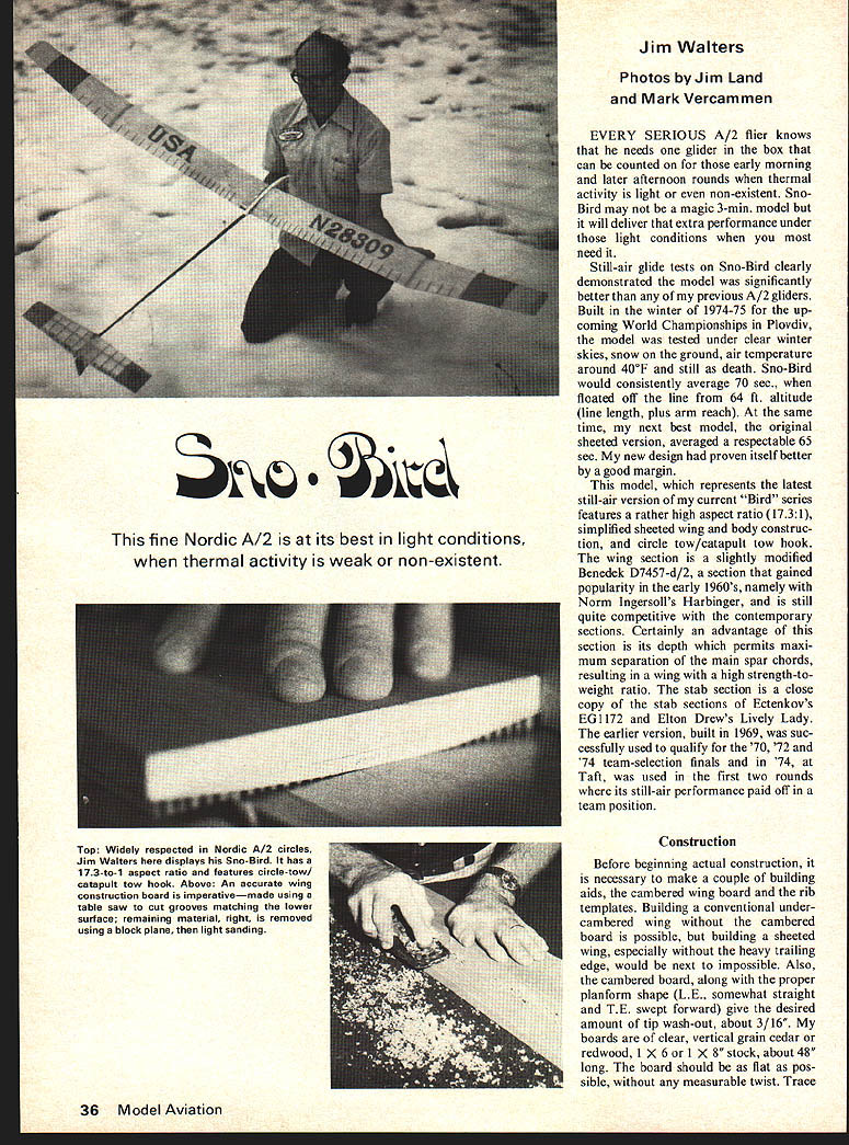
EVERY SERIOUS A/2 flier knows that he needs one glider in the box that can be counted on for those early morning and later afternoon rounds when thermal activity is light or even non-existent. Sno-Bird may not be a magic 3-min. model but it will deliver that extra performance under those light conditions when you most need it.
Still-air glide tests on Sno-Bird clearly demonstrated the model was significantly better than any of my previous A/2 gliders. Built in the winter of 1974-75 for the upcoming World Championships in Plovdiv, the model was tested under clear winter skies, snow on the ground, air temperature around 40°F and still as death. Sno-Bird would consistently average 70 sec. when floated off the line from 64 ft. altitude (line length, plus arm reach). At the same time, my next best model, the original sheeted version, averaged a respectable 65 sec. My new design had proven itself better by a good margin.
This model, which represents the latest still-air version of my current "Bird" series features a rather high aspect ratio (17.3:1), simplified sheeted wing and body construction, and circle tow/catapult tow hook. The wing section is a slightly modified Benedek D7457-d/2, a section that gained popularity in the early 1960's, namely with Norm Ingersoll's Harbinger, and is still quite competitive with the contemporary sections. Certainly an advantage of this section is its depth which permits maximum separation of the main spar chords, resulting in a wing with a high strength-to-weight ratio. The stab section is a close copy of the stab sections of Ectenkov's EG 1172 and Elton Drew's Lively Lady. The earlier version, built in 1969, was successfully used to qualify for the '70, '72 and '74 team-selection finals and in '74, at Taft, was used in the first two rounds where its still-air performance paid off in a team position.
Construction
Before beginning actual construction, it is necessary to make a couple of building aids, the cambered wing board and the rib templates. Building a conventional undercambered wing without the cambered board is possible, but building a sheeted wing, especially without the heavy trailing edge, would be next to impossible. Also, the cambered board, along with the proper planform shape (L.E. somewhat straight and T.E. swept forward) give the desired amount of tip wash-out, about 3/16". My boards are of clear, vertical grain cedar or redwood, 1 x 6 or 1 x 8 stock, about 48" long. The board should be as flat as possible, without any measurable twist. Trace the lower camber of the main rib onto the end of the board and, using the table saw, cut grooves (blade width), full length at approximately 3/16" intervals that just match the camber line (see photo). The remaining material is removed using a block plane and finally, a sanding block (see photo). A board will take 2 to 4 hours to build but easily makes up for it in ease of building. A wooden strip, approximately 3/8" X 3/4", screwed to the forward edge of the board, is used for indexing the rib locations and ensures a straight leading edge.
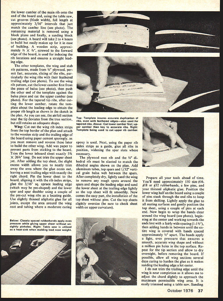
The other templates, the wing and stab rib patterns, made from 1/16" plywood, permit fast, accurate slicing of the ribs, particularly the wing ribs with their feathered trailing edge (see photo). To use the wing rib pattern, cut the lower camber first from the piece of balsa (see photo), then push the other end of the template against the balsa piece and cut the upper camber (see photo). For the tapered tip ribs, after cutting the lower camber, rotate the template about the leading edge to obtain the proper rib length as shown in the sketch in the plan. As you can see, the airfoil section near the tip deviates from the true section, but still retains an adequate shape.
Wing
Cut out the wing rib index strips from the top border of the plan and attach to the wooden strip and the trailing edge of the board using paper cement sparingly, as you must remove and reverse these later to build the other wing. Add wax paper to prevent parts from sticking to the board. Trim the lower inboard sheet exactly 5 5/8" X 26 1/4" long. Do not trim the upper sheet yet. After adding the top sheet, the slight excess width allows you to neatly trim away the area where the glue oozes out, leaving a neat trailing edge with exactly the right chord. Pin the lower sheet to the board, aligning it with the rib index strips, glue the 3/16" sq. spruce leading edge (which may be pre-shaped) and the lower spar and spar doubler using a couple of the pre-cut wing ribs as a locating guide. Use slightly thinned aliphatic glue for all joints, except the area around the wing root and tubing where a moderate curing epoxy is used. Next, using the paper rib index strips as a guide, glue all ribs in position, widening the spar slots where necessary.
The plywood root rib and the 5/8" dihedral rib must be slanted to match the dihedral angles shown on the plan. Add aluminum tubes, top spars and 1/32" vertical grain balsa web between the spars. After completely dry, lightly sand the wing to remove any rough spots around the spars and shape the leading edge and sand the lower sheet at the trailing edge lightly so the top sheet will fit smoothly. Now comes the easy part, the installation of the tip sheets without pins. Cut the top sheets slightly oversize (be sure to check sheet width on upper curvature).
Prepare all your tools ahead of time. You'll need approximately 150 size #16, #18 or #32 rubber bands, a few pins, and aliphatic glue. Position the lower wing sheet on the board using a couple of pins stuck through the end ribs to keep it from shifting. Lightly apply the glue to all mating surfaces and gently position the top sheet, using a couple of pins at each end. Now begin to wrap the bands clear around the wing board (see photo), beginning at the center and working towards the ends, beginning the ends first with a fairly wide spacing (1–1 1/2"), then adding bands in between until the entire wing is covered with bands spaced approximately 1/2" apart. The bands apply a light, even pressure that ensures a smooth, accurate wing shape and without a million pin holes in the top surface. Repeat for the tip section and allow to dry overnight, before removing the board. If possible, allow all wing sections several days curing to harden the glue as it makes sanding the leading edge a lot easier.
I do not trim the trailing edge until the wing is near completion as it allows me to adjust the chord slightly to approach the maximum permissible wing area. It is easily trimmed using a table saw. Sanding
Sno-Bird
sealer may be applied to the lower surface only but I believe the natural roughness of the balsa grain on the upper surface aids in turbulating the wing. Add trim, numbers and thread turbulator.
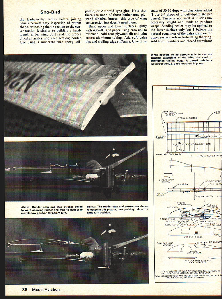
the leading-edge radius before joining panels permits inspection of proper shape. Attaching the tip section to the center section is similar to building a hand-launch glider wing. Just sand the proper dihedral angles into each section; double glue using a moderate cure epoxy, aliphatic, or Ambroid type glue. Note that there are none of those bothersome plywood dihedral braces—this type of wing construction just doesn't need them.
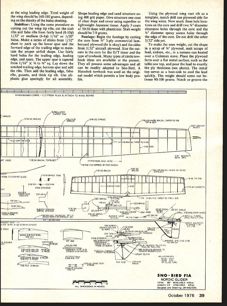
Top and lower surfaces lightly sand with 400-600 grit paper using care not to oversand. Add root plywood rib and trim excess aluminum tubing. Add soft balsa tips and trailing edge stiffeners. Give three coats of 50-50 dope with plasticizer added (I use 3-4 drops of di-butyl-phthalate per ounce). Tissue is not used as it adds unnecessary weight and tends to produce warps. at the wing leading edge. Total weight of the wing should be 160-180 grams, depending on the density of the balsa sheeting.
Stabilizer: Using the same procedure as for cutting out the wing tip ribs, cut the stab ribs and false ribs from fairly hard (8-10#) 1/32" or medium (6-8#) 1/16" or 1/20" balsa. Make a series of shims from 1/32" sheet to pack up the lower spar and the forward edge of the trailing edge to maintain the proper airfoil shape. Use fairly hard balsa for the trailing edge, leading edge, and spars. The upper spar is tapered from 1/16" X 1/8" to 1/16" X 1/16" sq. Lay down the notched trailing edge, bottom spar and add the ribs. Then add the leading edge, false ribs, gussets, and thick tip rib. Use aliphatic glue sparingly for all assembly.
Shape leading edge and sand structure using 400 grit paper. Give structure one coat of clear dope and cover using superfine or lightweight Japanese tissue. Apply 3 coats of 50-50 dope with plasticizer. Stab weight should be 7-9 grams.
Fuselage: Begin the fuselage by cutting the core from 3/8" 3-ply commercial lumberyard plywood (fir is okay) and the sides from 3/32" aircraft plywood. Size the cutouts in the core for the D/T timer and the type of towhook. Many types of circle towhook ideas are available at the present. They all possess some advantages and all can be readily adapted to Sno-Bird. A tandem snorkel which was used on the original model which permits a low body profile.
Using the plywood wing root rib as a template, match drill one plywood side for the wing wires. Now mark these hole locations on the core and drill two 1/4" diameter clearance holes through the core and the 1/4" diameter epoxy access holes through the edge of the core. Do not drill the other 3/32" side yet.
To make the nose weight, cut the shape in a scrap of 1/8" plywood, melt scraps of lead, sinkers, etc., in a tomato can heated over a Coleman stove. Place the plywood form over a flat metal surface, such as the table saw top, and pour the lead to exactly the ply thickness (see photo). The metal top serves as a heat-sink to cool the lead quickly. The weight should come out between 90-100 grams. Notch or groove the ply sides to match the fiberglass rod. Using moderate cure epoxy, assemble sides, core, hook supports, and tail boom using care to align the tailboom and, when dry, round edges except where wing mates with the fuselage. Now drill the wire holes through the other plywood side using the holes in the first side as a guide. Bend the two wing wires and install in holes, checking to see that the wires come out parallel or that there is slight wash-in (L.E. up in the right wing). The wash-in is necessary to keep the right wing from dipping during catapult launches and also tends to keep the model from spinning in when in turbulent air.
With the wires centered in the fuselage, but not glued, install the wings and rotate the wires as required (slightly aft) to match the high angle of the wing. If you neglect this, the wing will not fit flush against the fuselage sides. When you're satisfied with the fit-up, carefully remove the wings without disturbing the wires, and apply epoxy through the two access holes in the core.
Build the fin from soft 1/4" sheet and rudder from 1/8" sheet. Groove the base of the fin to match the fiberglass rod, add the short piece of aluminum tubing (1/32" I.D.), and, after shaping the fin to the proper airfoil shape, epoxy to the tailboom which has been pre-roughened with sandpaper to improve the adhesion of the adhesive.
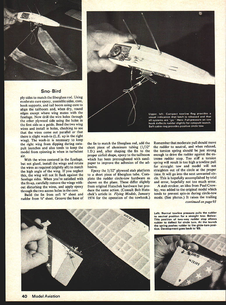
Epoxy the 3/32" plywood stab platform to a short piece of fiberglass tube. Complete the rudder circle-tow hardware as they show on the plans. These differ slightly from original Hatschek hardware but produce the same action. (Consult Bob Hatschek's article in Flying Models, January 1974 for the operation of the towhook.)
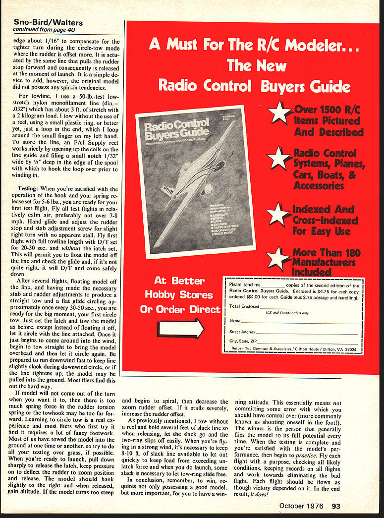
Remember that moderate pull should move the rudder to neutral, and when relaxed, the torsion spring should be just strong enough to drive the rudder against the extreme rudder stop. Too stiff a torsion spring will result in too high a towline pull for straight tow and model will not straighten out of the circle at the proper time. It will go into the next unwanted circle. This is hopefully accomplished by trial and error, hopefully not too much error.
A stab stroker, an idea from Paul Crowley, was added to the original model which tends to prevent spin-in during circle-tow mode. (See photos.) It raises the trailing edge about 1/16" to compensate for the tighter turn during the circle-tow mode where the rudder is offset more. It is actuated by the same line that pulls the rudder stop forward and consequently is released at the moment of launch. It is a simple device to add; however, the original model did not possess any spin-in tendencies.
For towline, I use a 50-lb. test low-stretch nylon monofilament line (dia. = .032") which has about 3 ft of stretch with a 2 kilogram load. I tow without the use of a reel, using a small plastic ring, or better yet, just a loop in the end, which I loop around the small finger on my left hand.
To store the line, an FAI Supply reel works nicely by opening up the coils on the line guide and filing a small notch 1/32" wide by 1/8" deep in the edge of the spool with which to hook the loop over prior to winding in.
Testing: When you're satisfied with the operation of the hook and your spring release set for 5-6 lbs., you are ready for your first test flight. Fly all test flights in relatively calm air, preferably not over 7-8 mph. Hand glide and adjust the rudder stop and stab adjustment screw for slight right turn with no apparent stall. Fly first flight with full towline length with D/T set for 20-30 sec. and without the latch set. This will permit you to float the model off the line and check the glide and, if it's not quite right, it will D/T and come safely down.
After several flights, floating model off the line, and having made the necessary stab and rudder adjustments to produce a straight tow and a flat glide circling approximately once every 30-50 sec., you are ready for the big moment, your first circle tow. Just set the latch and tow the model as before, except instead of floating it off, let it circle with the line attached. Once it just begins to come around into the wind, begin to tow straight to bring the model overhead and then let it circle again. Be prepared to run downwind fast to keep line slightly slack during downwind circle, or if the line tightens up, the model may be pulled into the ground. Most fliers find this out the hard way.
If the model will not come out of the turn when you want it to, then there is too much spring force in the rudder torsion spring or the towhook may be too far forward. Learning to circle tow is a real experience and most fliers who first try it find it requires a lot of fancy footwork. Most of us have towed the model into the ground at one time or another, so try to do all your testing over grass, if possible.
When you're ready to launch, pull down sharply to release the latch, keep pressure on to deflect the rudder to zoom position and release. The model should bank slightly to the right and when released, gain altitude. If the model turns too steep and begins to spiral, then decrease the zoom rudder offset. If it stalls severely, increase the rudder offset.
As previously mentioned, I tow without a reel and hold several feet of slack line so when releasing, let the slack go and the tow-ring slips off easily. When you're flying in a strong wind, it's necessary to keep 8-10 ft. of slack line available to let out quickly to keep load from exceeding unlatch force and when you do launch, some slack is necessary to let tow-ring slide free.
In conclusion, remember, to win, requires not only possessing a good model, but more important, for you to have a winning attitude. This essentially means not committing some error with which you should have control over (more commonly known as shooting oneself in the foot!). The winner is the person that generally flies the model to its full potential every time. When the testing is complete and you're satisfied with the model's performance, then begin to practice. Fly each flight with a purpose, checking all likely conditions, keeping records on all flights and, working toward eliminating the bad flight. Each flight should be flown as though victory depended on it. In the end result, it does!
Transcribed from original scans by AI. Minor OCR errors may remain.

