
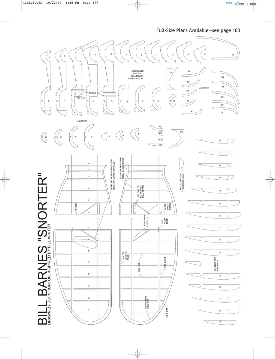
Snorter
by John Hunton
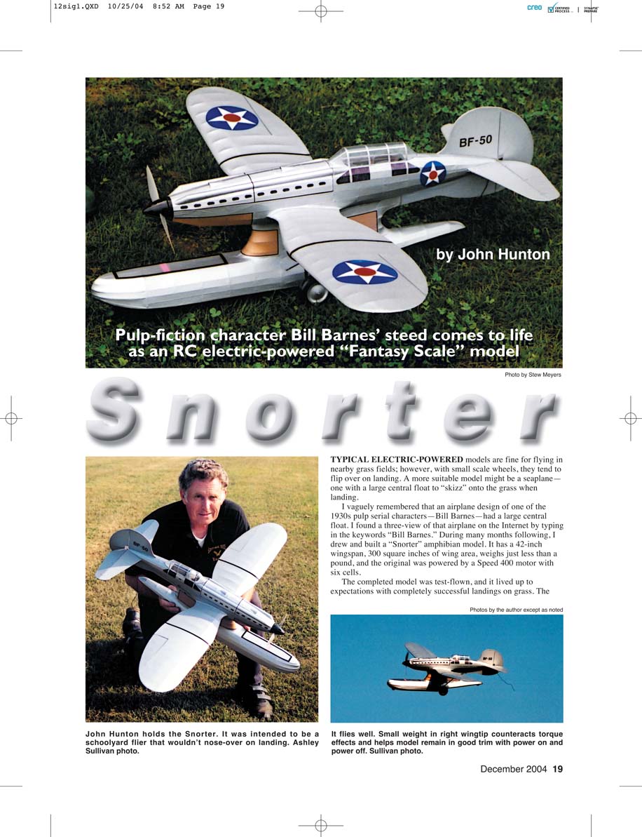
TYPICAL electric-powered models are fine for flying in nearby grass fields; however, with small-scale wheels they tend to flip over on landing. A more suitable model might be a seaplane—one with a large central float to "skizz" onto the grass when landing.
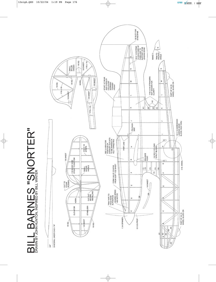
I vaguely remembered that an airplane design of one of the 1930s pulp-serial characters—Bill Barnes—had a large central float. I found a three-view of that airplane on the Internet by typing the keywords "Bill Barnes." During many months following, I drew and built a Snorter amphibian model. It has a 42-inch wingspan, about 300 square inches of wing area, weighs just less than a pound, and the original prototype was powered by a Speed 400 motor with six cells. The completed model was test-flown and it lived up to expectations with completely successful landings on grass.
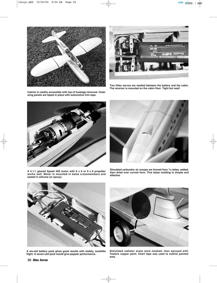
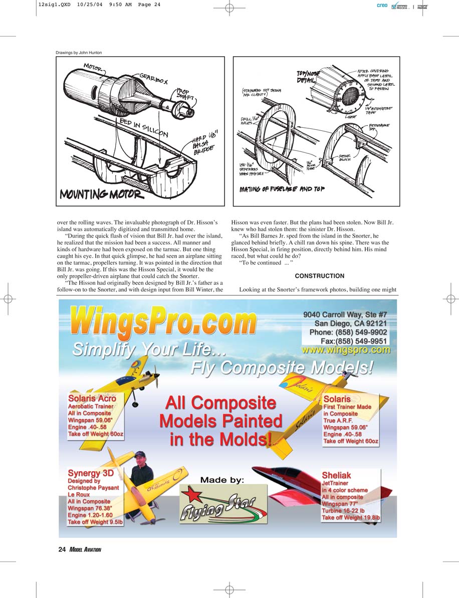
A 4.1:1 geared Speed 400 motor with an 8 x 6 or 9 x 6 propeller works well. The motor is mounted in balsa crossmembers and seated in silicone (or epoxy). The interior is readily accessible with the top of the fuselage removed. Outer wing panels are taped in place with automotive trim tape. Two Hitec servos are nestled between the battery and the cabin; the receiver is mounted on the cabin floor—tight but neat!
Simulated carburetor air scoops are formed from 1/32" balsa, wetted, then dried over a curved form. This balsa molding is simple and effective. Simulated radiator areas were masked, then sprayed with Testors copper paint; chart tape was used to outline the painted area. A six-cell battery pack gives stately, scalelike flight; a seven-cell pack would give peppier performance.
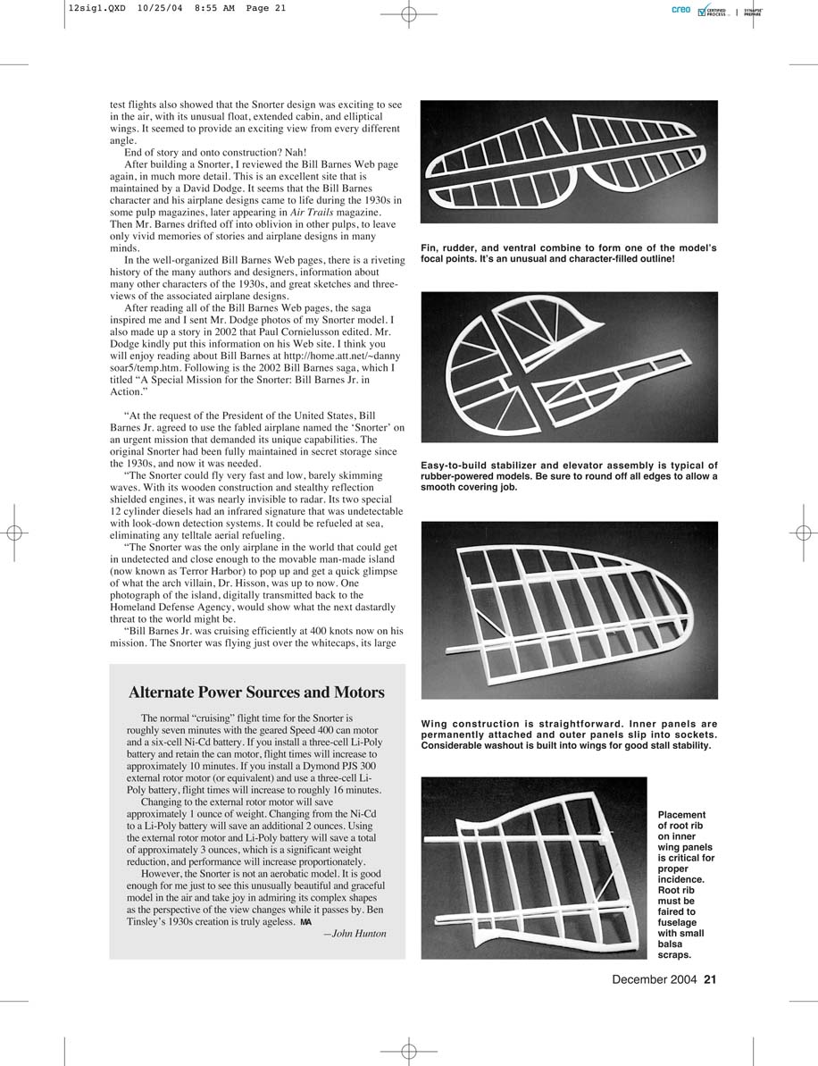
Easy-to-build stabilizer and elevator assembly is typical of rubber-powered models—be sure to round off all edges to allow a smooth covering job. Placement of the root rib on the inner wing panels is critical for proper incidence; the root rib must be faired to the fuselage with small balsa scraps. Wing construction is straightforward: inner panels are permanently attached and outer panels slip into sockets. Considerable washout is built into the wings for good stall stability.
The fin, rudder, and ventral fin combine to form one of the model’s focal points. It’s an unusual and character-filled outline. Test flights showed the Snorter design was exciting to see in the air, with its unusual float, extended cabin, and elliptical wings—providing an engaging view from every angle.
After building a Snorter, I reviewed the Bill Barnes web pages in much more detail. This excellent site is maintained by David Dodge and contains a riveting history of many authors and designers, information about other 1930s characters, and great sketches and three-views of associated airplane designs. Inspired, I sent Mr. Dodge photos of my Snorter model and I also made up a short story in 2002 that Paul Cornielusson edited.
Fictional Mission (excerpt)
"At the request of the President of the United States, Bill Barnes Jr. agreed to use the fabled airplane named the 'Snorter' on an urgent mission that demanded its unique capabilities. The original Snorter had been fully maintained in secret storage since the 1930s, and now it was needed.
"The Snorter could fly very fast and low, barely skimming waves. With its wooden construction and stealthy reflection-shielded engines, it was nearly invisible to radar. Its two special 12-cylinder diesels had an infrared signature undetectable with look-down detection systems. It could be refueled at sea, eliminating any telltale aerial refueling.
"The Snorter was the only airplane in the world that could get in undetected and close enough to the movable man-made island (now known as Terror Harbor) to pop up and get a quick glimpse of what the arch-villain, Dr. Hisson, was up to. One photograph of the island, digitally transmitted back to the Homeland Defense Agency, would show what the next dastardly threat to the world might be.
"Bill Barnes Jr. was cruising efficiently at 400 knots, the Snorter's main float wet from ocean spray. When cruising, the Snorter used only one diesel to save fuel, but on approaching the island Bill Jr. fired up the other engine and its contra-rotating propeller.
"Airspeed climbed well past 500 mph—this speed achievable because all defensive weaponry had been removed to aid in stealth and speed. A special 'look-up' camera had been installed for the desired overall shot of the island.
"Of course, the diabolical Dr. Hisson tracked all satellites and always covered up his operations when they passed overhead. Snorter was going to make its run between satellite passes to catch the island with everything exposed.
"The island grew large in the windshield and it was time for Bill Jr. and the Snorter to pop up. When Bill Jr. pulled on the yoke the G-meter read 9. He slammed the stick to the right to start the roll and was immediately inverted over the island. The upward-looking camera, now facing downward, was triggered. Bill rolled level again just past the island at only a few feet above the surface."
Alternate Power Sources and Motors
The normal cruising flight time for the Snorter is roughly seven minutes with the geared Speed 400 can motor and a six-cell Ni-Cd battery. Other options:
- Keep the can motor and install a 3-cell Li-Poly battery: flight time increases to ~10 minutes.
- Install a Dymond PJS 300 external-rotor motor (or equivalent) and use a 3-cell Li-Poly battery: flight time increases to ~16 minutes.
Weight and performance considerations:
- Changing to the external-rotor motor saves ~1 ounce.
- Changing from Ni-Cd to Li-Poly saves ~2 ounces.
- Using both the external-rotor motor and Li-Poly saves ~3 ounces total, a significant reduction that increases performance proportionately.
Note: The Snorter is not an aerobatic model. It is gratifying to see this unusual, graceful model in the air and to admire its complex shapes as perspectives change.
—John Hunton
Construction
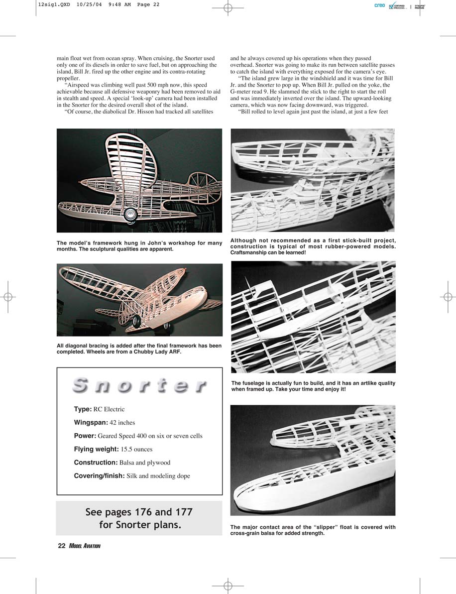
Looking at the Snorter's framework photos, building one might seem more difficult than it really is. The fuselage is a simple box structure of medium balsa with a removable top for access. The fuselage sides are sheeted with 1/16" balsa; formers are spaced 1" apart in the cabin area and 1-1/2" in the tailboom area. The float is built in two halves over a crutch and glued to the fuselage bottom.
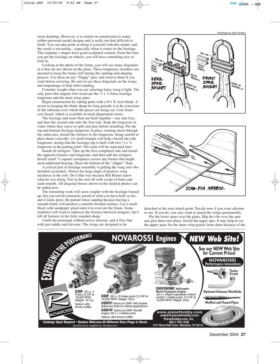
Wing construction is straightforward. Inner panels are permanently attached and outer panels slip into sockets. Placement of the root rib on the inner wing panels is critical for proper incidence; the root rib must be faired to the fuselage with small balsa scraps. Considerable washout is built into the wings for good stall stability.
Easy-to-build stabilizer and elevator assembly is typical of rubber-powered models—round all edges to allow a smooth covering job.
A 4.1:1 geared Speed 400 motor with an 8 x 6 or 9 x 6 propeller works well. The motor is mounted in balsa crossmembers and seated in silicone (or epoxy). The interior is readily accessible with the top of the fuselage removed. Outer wing panels are taped in place with automotive trim tape. Two Hitec servos fit between the battery and the cabin; the receiver is mounted on the cabin floor—tight but neat!
Simulated carburetor air scoops are formed from 1/32" balsa, wetted, then dried over a curved form. Simulated radiator areas were masked, then sprayed with Testors copper paint; chart tape outlined the painted area.
A six-cell battery pack gives good results with stately, scalelike flight. A seven-cell pack gives peppier performance.
Construction tips:
- Use temporary diagonal bracing in frames and wings to keep parts stiff during sanding and shaping; remove them before covering if desired.
- Consider weight when selecting balsa; the lightest suitable wood is best. The only parts that require firm wood are the 1/4" x 1/8" fuselage longerons and the main wing spars.
- Begin construction by cutting parts with a #11 X-Acto blade; cut over foam-core board to keep the blade sharp.
- Build the fuselage and main float together—one side first, then the other. Soak longerons where they curve, glue, and pin in place. Install formers vertically and add side longerons. The fuselage top is built with two 1/4" x 1/8" longerons at the parting joint, separated later.
- Install all stringers and small 1/16" square crosspieces for additional bracing where needed. Sheet the bottom of the slipper float.
- Fair the wing root ribs accurately; the root rib fits at approximately 4° positive incidence—do it that way. Sand smooth and add diagonal braces shown in skeletal photos.
- Some builders undercut formers between stringers for a lighter shell; I left all formers fully rounded.
- Decide whether to have active ailerons; the prototype flew fine with just rudder and elevator. The wings are designed to detach at the strut attach point—if you want ailerons, consider attaching the wings permanently.
Wing assembly:
- Pin the lower spars over the plans, slip ribs over the spar, and glue them into place. Install the upper spar; for inner panels it may help to cut upper spars from sheet because of the curvature.
- Dry-fit leading and trailing edges, do most rough shaping off the wing, then glue into place. After drying, sand lightly with a large block.
Tail assembly:
- Assemble tail-piece outlines over the plans, install harder balsa spars and crosspieces, let dry, then block-sand smooth and flat.
- To put a radius on tail edges, make a small block with the proper inside radius and work it around the edges.
- Wing struts are 1/8" x 1/4" firm balsa, shaped to a streamlined cross-section; add two threads on each side, bedded into glue, for reinforcement.
Covering
After trying several covering methods on the prototype, including Japanese tissue and heat-shrink materials, I settled on lightweight silk applied with Sig butyrate dope to work around the model’s many curves. Silk is an incredibly flexible material.
Covering steps:
- Prep the entire frame and lightly resand.
- Cut silk oversize, sprinkle with water, redope the area, and pin the silk into place, minimizing wrinkles around edges.
- Where silk will be in tension over a rib, former, or stringer, use model cement to adhere it so it will not pull loose later.
- If wrinkles appear, use a covering iron to remove them.
- Seal the silk with 50-50 thinned dope, then apply two more coats of butyrate clear.
- I brushed on a thinned coat of silver dope, lightly sanded, then sprayed the final coat—keep coats light.
- Small wrinkles will disappear with time or can be heat-gunned out.
- I covered all flying surfaces, including the large subrudder, with CoverLite applied with Sig adhesive.
Final Assembly
Presuming you kept flying surfaces relatively flat during covering, now is the time to warp them:
- Slip the inner wing panels into the fuselage. The wing root rib fits at approximately 4° positive incidence.
- Apply heat and warp the panels so the tips are roughly 2° at the end of the inner wing panel. Sight from the nose to ensure both panels are equally bent.
- Install wing struts to stabilize inner panels. Slip outer panels into place and warp the tips so the flat bottoms are even with the fuselage centerline (zero incidence reference is the flat bottom, not the true airfoil chord line).
- Install the empennage with reference to the wing for accurate alignment.
- Install horns, hinges, sheaths, servos, and lightweight pushrods. Control-surface movement should be about 20° from neutral.
- Install the motor with propeller and the receiver. Finalize the balance point with the battery pack—the heaviest item. Make sure the model balances where indicated, even if ballast front or rear is needed.
- Trim: I added all trim with a felt-tipped pen for light weight. I suggest you do not fly the model off water or use the tip floats.
Flying
I used a Speed 400 motor with a 4:1 gearbox and an APC 8 x 6 propeller in the prototype with a six-cell battery for realistic flight. The prototype has since been upgraded with an external-rotor (outrunner) motor and Li-Poly cells while still driving the same propeller; flight time doubled and performance increased nicely.
Since the Snorter presents an unusual countenance in the air, keep it close in until you get used to its shapes. Keep speed up after hand launching until it gains altitude. Keep a little power on for improved rudder authority on landing.
Observe tracking during a straight flyby. If it yaws, use the semifixed ailerons to counter the effect: a bit of right aileron will cause the model to yaw left; the opposite is true for left aileron.
I hope you enjoy the Snorter and its heritage as much as I have. This model will mean a lot to many people at the flying field and will jog many memories—don't tell them right off what it is; let them try to guess for a while.
—John Hunton 9154 Rixeyville Rd. Rixeyville, VA 22737
BILL BARNES "SNORTER"
Drawn by John Hunton, inspired by Bill Winter Full-size plans available—see page 183
Transcribed from original scans by AI. Minor OCR errors may remain.

