
So Long But Not Forgotten
Harry Murphy
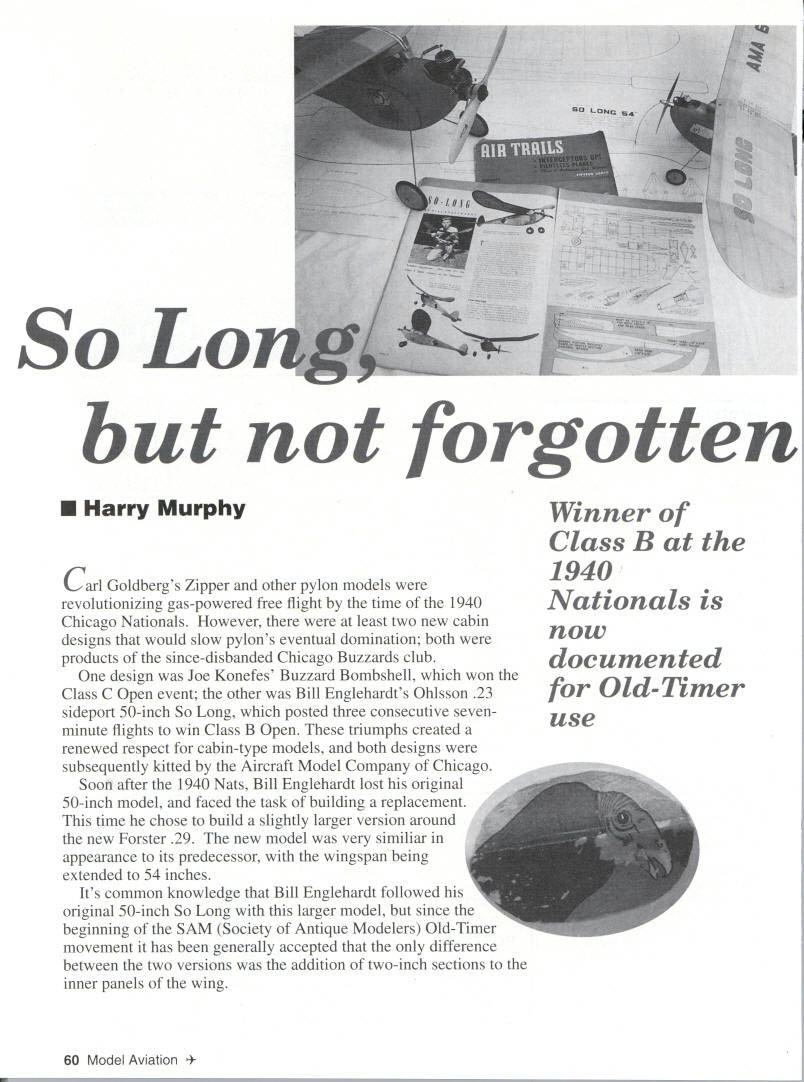
Carl Goldberg's Zipper and other pylon models were revolutionizing gas-powered free flight by the time of the 1940 Chicago Nationals. However, there were at least two new cabin designs that would slow pylon's eventual domination; both were products of the since-disbanded Chicago Buzzards club.
One design was Joe Konefes' Buzzard Bombshell, which won the Class C Open event; the other was Bill Englehardt's Ohlsson .23 sideport 50-inch So Long, which posted three consecutive seven-minute flights to win Class B Open. These triumphs created a renewed respect for cabin-type models, and both designs were subsequently kitted by the Aircraft Model Company of Chicago.
Soon after the 1940 Nats, Bill Englehardt lost his original 50-inch model and faced the task of building a replacement. This time he chose to build a slightly larger version around the new Forster .29. The new model was very similar in appearance to its predecessor, with the wingspan being extended to 54 inches.
It's common knowledge that Bill Englehardt followed his original 50-inch So Long with this larger model, but since the beginning of the SAM (Society of Antique Modelers) Old-Timer movement it has been generally accepted that the only difference between the two versions was the addition of two-inch sections to the inner panels of the wing.
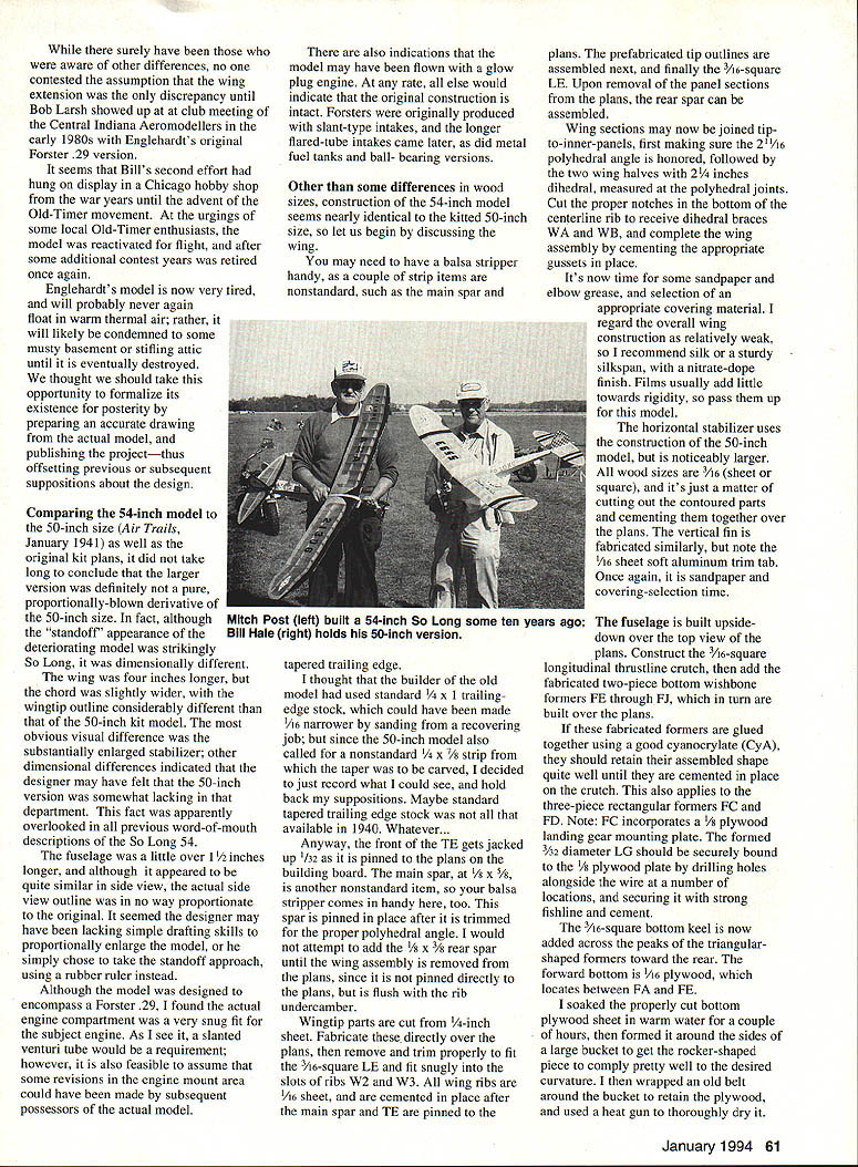
But forgotten surely have been awareness of other differences. The contested assumption that the wing-extension discrepancy was the only one continued until Bob Larsh showed up at a club meeting of the Central Indiana Aeromodellers in the early 1980s. Englehardt's Forster .29 version — what seems to be Bill's second effort — hung on display in a Chicago hobby shop during the war years until the advent of the Old-Timer movement. At the urgings of some local Old-Timer enthusiasts the model was reactivated and flown for some additional contest years, then retired once again. Englehardt's model is now very tired and will probably never again float in warm thermal air; rather it will likely be condemned to some musty basement or stifling attic until eventually destroyed. I thought I should take the opportunity to formalize its existence for posterity by preparing an accurate drawing of the actual model and publishing the project, thus offsetting previous and subsequent suppositions about the design.
Comparing the 54-inch model with the 50-inch size in Air Trails, January 1941, as well as the original kit plans, it did not take long to conclude the larger version was definitely not a pure proportionally blown derivative of the 50-inch size. In fact, although the stand-off appearance of the deteriorating model was strikingly similar, So Long was dimensionally different. The wing was four inches longer, the chord slightly wider, and the wingtip outline considerably different from the 50-inch kit model. There was an obvious visual difference in the substantially enlarged stabilizer and other dimensional differences, indicating the designer may have felt the 50-inch version was somewhat lacking in that department — a fact apparently overlooked in previous word-of-mouth descriptions.
The So Long 54 fuselage is a little over 1/2 inch longer, although it appears quite similar in side view. The actual side-view outline is in no way proportionate to the original; it seems the designer, perhaps lacking simple drafting skills to proportionally enlarge the model, simply chose a stand-off approach using a rubber ruler instead.
Although the model was designed to encompass the Forster .29, the actual engine compartment was a very snug fit for that engine. As seen, the slanted venturi tube would be a requirement; however, it is also feasible to assume some revisions to the engine-mount area could have been made by subsequent possessors of the actual model. There are also indications the model may have flown a glow-plug engine at some point; otherwise the original construction would not be intact. Forsters were originally produced with slant-type intakes; longer flared-tube intakes came later, as did metal fuel tanks and ball-bearing versions. Other differences concern wood sizes and construction. The 54-inch model seems nearly identical in kit layout to the 50-inch size.
Let us begin discussing the wing. You may need to have a balsa stripper handy for a couple of strip items that are nonstandard, such as the main spar and the tapered trailing edge. I thought the builder of the old model used standard trailing-edge stock, which could have been made narrower by sanding during the recovering job, since the 50-inch model also calls for a nonstandard strip taper carved into the trailing edge. I decided just to record what could be seen and hold back suppositions. Maybe standard tapered trailing-edge stock was available in 1940.
Anyway, the front trailing edge (TE) gets jacked up 1/32 inch and pinned to the plans on the building board. The main spar is another nonstandard item where a balsa stripper comes in handy. This spar is pinned in place after it is trimmed for the proper polyhedral angle. I would not attempt to add the 1/8 x 3/8-inch rear spar until the wing assembly is removed from the plans, since it is not pinned directly to the plans but is flush with the rib undercamber.
Wingtips parts are cut from 1/4-inch sheet. Fabricate these directly over the plans, then remove and trim properly to fit the 3/16-inch square leading edge (LE) and fit snugly into the slots of ribs W2 and W3. All wing ribs are 1/16-inch sheet and are cemented in place after the main spar and TE are pinned to the plans. The prefabricated tip outlines are assembled next, and finally the 3/16-inch square LE. Upon removal of the panel sections from the plans, the rear spar can be assembled.
Wing sections may now be joined tip-to-inner-panels, first making sure the 2-1/16-inch polyhedral angle is honored, followed by the two wing halves with 2-1/4 inches dihedral, measured at the polyhedral joints. Cut the proper notches in the bottom of the centerline rib to receive dihedral braces WA and WB, and complete the wing assembly by cementing the appropriate gussets in place.
It's now time for some sandpaper and elbow grease, and selection of an appropriate covering material. I regard the overall wing construction as relatively weak, so I recommend silk or a sturdy silkspan, with a nitrate-dope finish. Films usually add little toward rigidity, so pass them up for this model.
The horizontal stabilizer uses the construction of the 50-inch model but is noticeably larger. All wood sizes are 3/16-inch (sheet or square), and it's just a matter of cutting out the contoured parts and cementing them together over the plans. The vertical fin is fabricated similarly, but note the 1/16-inch sheet soft aluminum trim tab. Once again, it is sandpaper and covering-selection time.
The fuselage is built upside-down over the top view of the plans. Construct the 3/16-inch square longitudinal thrustline crutch, then add the fabricated two-piece bottom wishbone formers FE through FJ, which in turn are built over the plans.
If these fabricated formers are glued together using a good cyanoacrylate (CyA), they should retain their assembled shape quite well until they are cemented in place on the crutch. This also applies to the three-piece rectangular formers FC and FD. Note: FC incorporates a 1/8-inch plywood landing gear mounting plate. The formed 3/32-inch diameter landing gear (LG) should be securely bound to the 1/8-inch plywood plate by drilling holes alongside the wire at a number of locations and securing it with strong fishline and cement.
The 3/16-inch square bottom keel is now added across the peaks of the triangular-shaped formers toward the rear. The forward bottom is 1/16-inch plywood, which locates between FA and FE.
I soaked the lower center fuselage plywood in warm water for a couple of hours, then formed it around the sides of a large bucket to get the rocker-shaped turn required to comply pretty well with the desired curvature. I then wrapped an old belt around the bucket to retain the plywood, and used a heat gun to thoroughly dry it. This preforming effort greatly facilitated assembly of the stiff plywood sheet in its proper location.
The assembly can now be removed from the plans, and the top portion of each former station may be cemented in place, followed by the 3/16-inch square backbone atop the formers between stations FE and FJ. Next add the wing saddle with proper dihedral angle built in.
The 1/8-inch plywood firewall (FA) is next, and the landing-gear former reinforcement doublers of 1/8-inch sheet can follow. Don't forget the vertical strips of 3/16-inch square that span the space between the keel and the backbone at stations FF through FJ. Add the instrument panel former FB, the wing hooks, and assemble the hardwood motor mounts through the slots in FA, noting the 1° downthrust.
You should now have a rather sturdy skeleton, ready to mount your engine, add your ignition paraphernalia, and ultimately add the 1/16-inch sheet balsa skin. I suggest that the coil, timer, and wiring be installed at this point—sans battery location—then plank the bottom half of the fuselage and complete the engine cowling area.
You may wish to temporarily assemble the engine (with prop), wheels, and the completed stabilizer to determine the approximate location of the flight batteries for the model to balance at 50% of the wing chord. Once the battery location is established, the top half of the fuselage can be planked with battery-hatch provisions being incorporated.
Sand the fuselage to a smooth finish, adding the 1/16-inch sheet balsa stab platform and celluloid windscreens. Seal the balsa skin with sanding sealer, add an appropriate number of coats of nitrate dope, and cover with silk or silkspan.
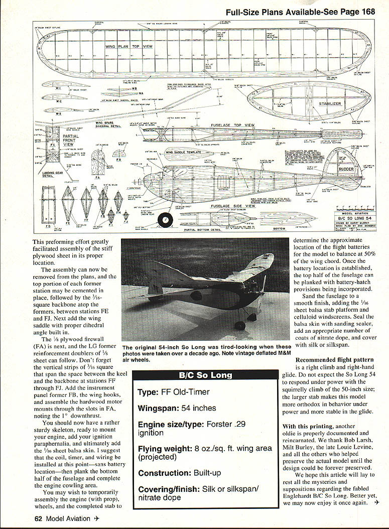
B/C So Long
- Type: FF Old-Timer
- Wingspan: 54 inches
- Engine size/type: Forster .29 ignition
- Flying weight: 8 oz./sq. ft. wing area (projected)
- Construction: Built-up
- Covering/finish: Silk or silkspan, nitrate dope
Recommended flight pattern is a right climb and right-hand glide. Do not expect the So Long 54 to respond under power with the squirrelly climb of the 50-inch size; the larger stabilizer makes this model more orthodox in behavior under power and more stable in the glide.
With this printing, another oldie is properly documented and reincarnated. We thank Bob Larsh, Milt Burley, the late Louie Levine, and all the others who helped preserve the actual model until the design could be forever preserved.
We hope this article will lay to rest all the mysteries and suppositions regarding the fabled Englehardt B/C So Long. Better yet, we may now enjoy it once again.
Transcribed from original scans by AI. Minor OCR errors may remain.

