
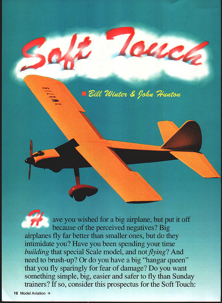
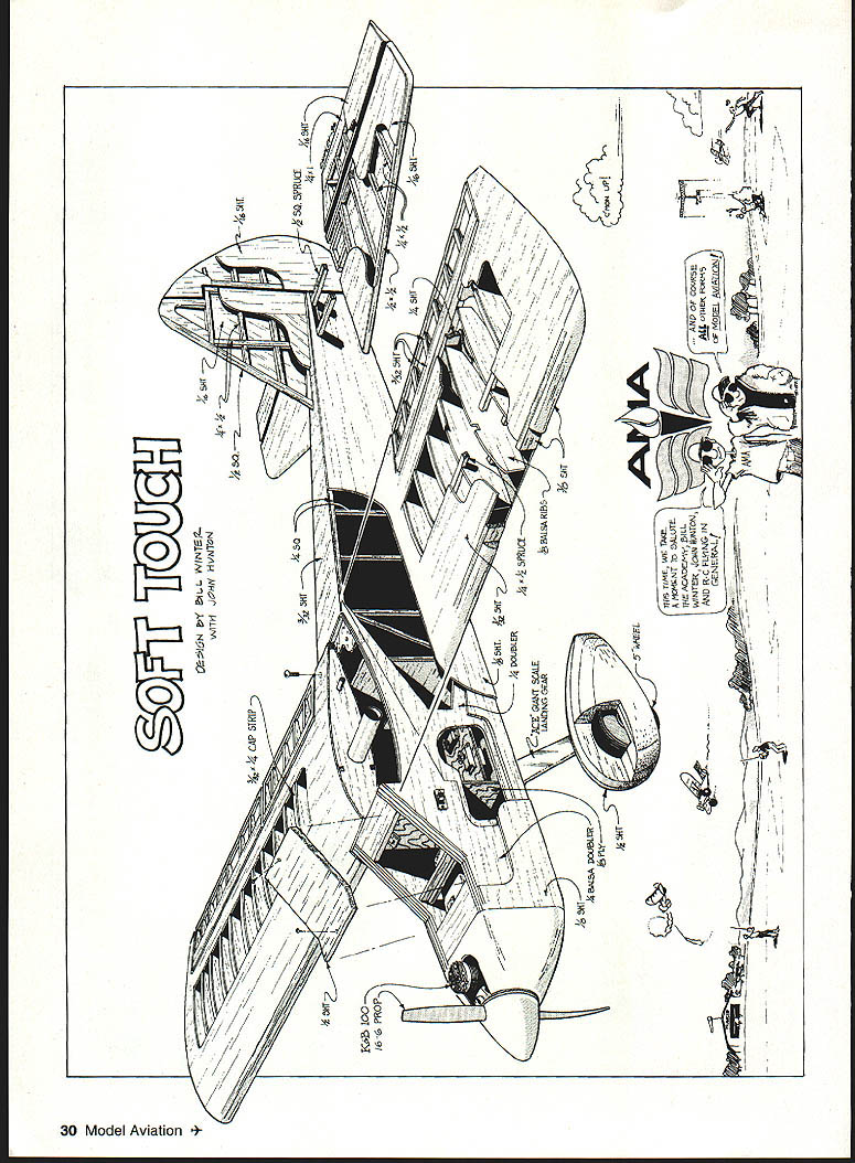
Soft Touch
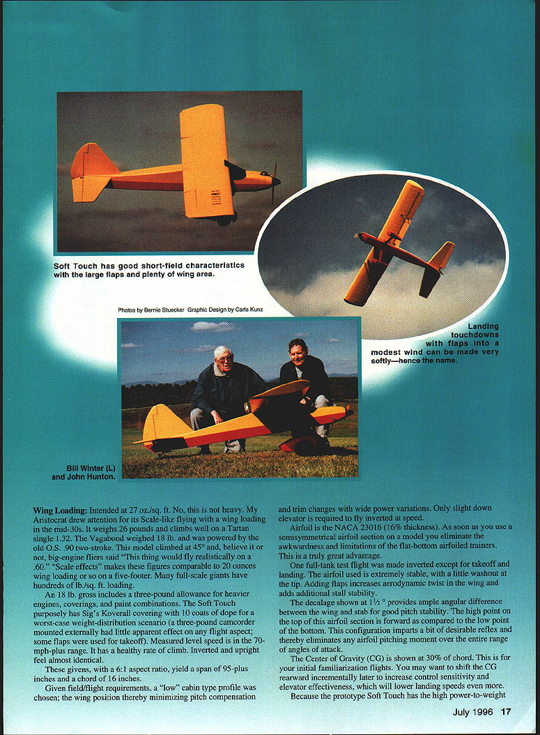
Bill Winter & John Hunton
Have you wished for a big airplane but put it off because of the perceived negatives? Big airplanes fly far better than smaller ones, but do they intimidate you? Have you been spending your time building that special scale model and not flying, or do you have a big "hangar queen" that you fly sparingly for fear of damage? Do you want something simple, big, easier and safer to fly than Sunday trainers? If so, consider this prospectus for the Soft Touch.
Wing Loading
- Intended wing loading: 27 oz./sq. ft.
- This is not heavy for a large model. For comparison, the Aristocrat drew attention for its scale-like flying with wing loading in the mid-30s. It weighed 26 lb. and climbed well on a Tartan single .32. The Vagabond weighed 18 lb. and was powered by an O.S. .90 two-stroke; it climbed steeply and many big-engine fliers said it "would fly realistically on a .60."
- Design gross weight: ~18 lb. (includes 3 lb. allowance for heavier engines, coverings, paint, ballast, etc.)
- The Soft Touch prototype used Sig Koverall covering with 10 coats of dope for a worst-case weight-distribution scenario. A 3 lb. external camcorder had little apparent effect on flight.
- Performance: measured level speed 70+ mph, healthy climb rate, inverted and upright feel nearly identical.
- Wing geometry:
- Aspect ratio: 6:1
- Span: 95+ inches
- Chord: 16 inches
- Airfoil: NACA 23016 (16% thickness), semi-symmetrical
- Semisymmetrical airfoil eliminates limitations of flat-bottom trainer sections and provides better overall handling and stability.
- A little washout at the tip and addition of flaps increases stall stability.
- Trim and balance:
- Decalage: 1° between wing and stabilizer for good pitch stability.
- CG: start at 30% of chord for familiarization flights; you may shift CG rearward incrementally later to increase control sensitivity and elevator effectiveness and to lower landing speeds.
- Cabin profile:
- "Low" cabin-type profile chosen to minimize pitch compensation and trim changes with large power variations; only slight down elevator needed to fly inverted at speed.
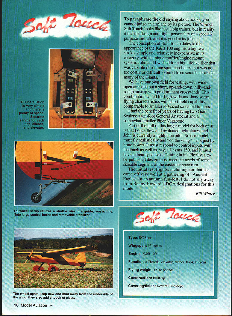
The Soft Touch looks like a big trainer but has the design and flight personality of a special-purpose aircraft. The conception dates to the appearance of the K&B 100 engine — a big, relatively inexpensive two-stroke with a unique muffler/engine mount — and the desire for a big, lifelike flier capable of routine sport aerobatics without excessive cost or build difficulty.
Initial test flights, including aerobatics, were successful at an "Ancient Eagles" fun-fest. The Soft Touch provides realistic "on the wing" feedback rather than just brute-power handling.
Specifications
- Type: RC sport model
- Wingspan: 95 inches
- Engine (prototype): K&B 100
- Controls: throttle, elevator, rudder, flaps, ailerons
- Flying weight: 15–18 pounds (design around 18 lb. gross)
- Construction: built-up balsa/plywood
- Covering/finish: Sig Koverall and dope
- Servos: eight total (two for each flap and aileron, plus elevator, rudder, throttle)
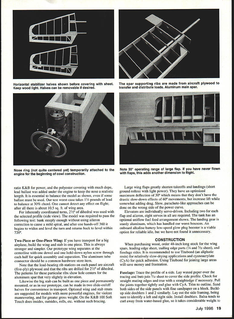
- Flaps: large, optimized max deflection 30° for increased lift with moderate drag
- Dihedral: 2.5° for inherently coordinated turns
- Landing gear: sturdy aluminum gear; optional struts for higher gross weights or aggressive maneuvering
- Fuel: standard fuel with up to 10% nitromethane used in testing
- Propeller: use wood props only
Handling note
- The model was required to pass this test: bank steeply without aileron correction to induce a mild spiral, and after one hands-off 360° it should begin to widen and level the turn, returning to level within 720°.
Two-Piece or One-Piece Wing
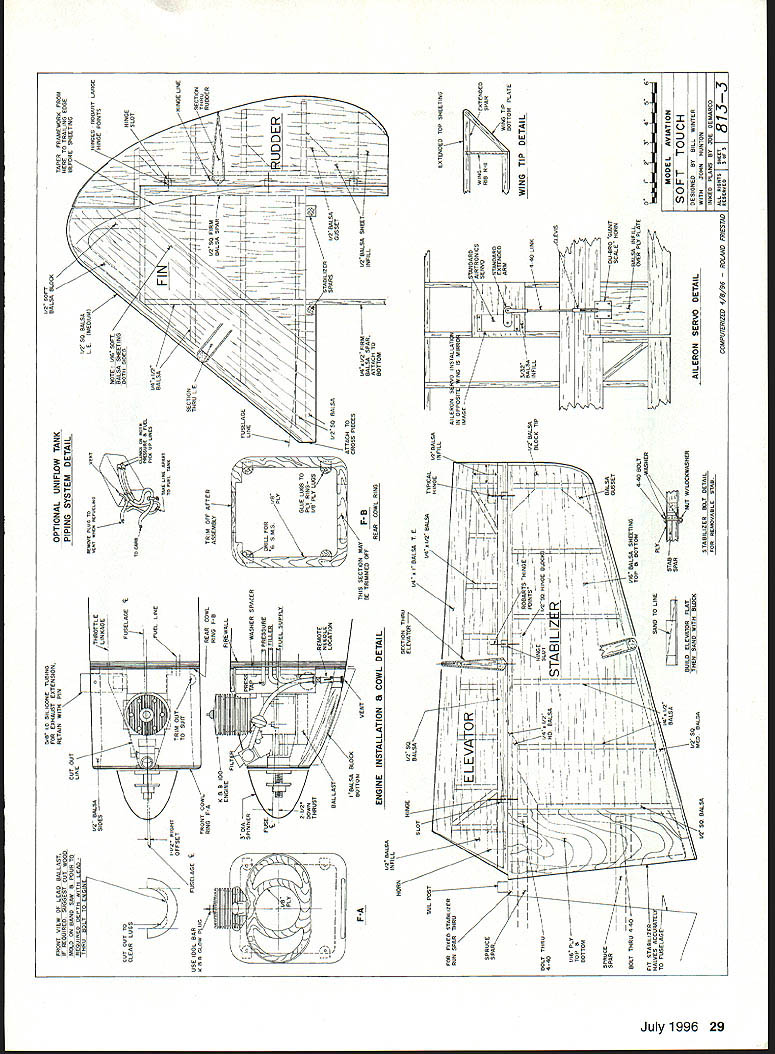
- If you transport a big airplane, build the wing and stabilizer in one piece for strength and simplicity. The prototype wing separates at the centerline using one dowel and one hold-down nylon screw through each half for quick assembly; an aluminum tube connector is used and is a common hardware-store item.
- Load-bearing rib stations on each panel are five-ply aircraft plywood; ribs are drilled for 2.5° dihedral. Patterns show hole centers for the aluminum spar slightly offset in elevation.
- Stabilizer: can be one piece, permanently mounted, or made in two slide-on/off halves for transport convenience.
- Optional struts are suggested for engines larger than the K&B 100, for violent maneuvering, or for greater gross weight; the prototype performs aerobatics without such bracing.
- Servo layout and systems:
- Elevators individually servo-driven.
- Two servos each for flaps and ailerons (eight servos total).
- Tank may have an optional uniflow fuel feed arrangement.
- Onboard alkaline battery glow-plug booster optional for reliable idle; not required in prototype.
- Flaps greatly shorten takeoffs and landings and permit slow, parachute-like approaches.
Construction
When purchasing wood, order 48-inch long stock for wing spars, leading-edge sheet, trailing-edge parts (1/4" and 3/32" sheets), and fuselage sides. Recommended adhesives:
- Titebond (aliphatic resin) for larger-area joints and for economical, forgiving glueing.
- Cyanoacrylate (CyA) for quick adhesion and spot joints.
- Use 30-minute epoxy where structural strength is critical (e.g., landing gear block).
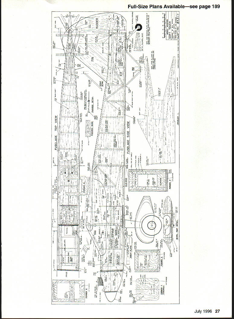
Fuselage
- Trace the fuselage side profile on the plan. Lay waxed paper over the tracing.
- Butt-join 3/32" sheet to cover the side profile. Check mating edges with a straightedge; pull joints together tightly and glue with CyA. Trim to outline and sand both sides with a block.
- Build up side doublers (1/2") similarly. Lay out side framing and identify left and right sides; install doublers.
- Note: balsa tends to curl away from water-based glue; use weights (stacks of books) to hold laminates together until cured.
- Install 1/4" square longerons, nose hatch supports, and all verticals/diagonal crossmembers.
- Cut plywood formers. Inside cutout corners are designed for a 1" Forstner bit to produce nicely finished holes.
- Slip-fit formers (C, D, E), trim as necessary, then glue onto one side using a small triangle to hold formers vertical.
- Place partly assembled sides over the top view, slip the tailpost into place, check vertical alignment, and glue the tails of the sides together.
- Cut remaining plywood parts. Install blind nuts in firewall and landing gear mount using 6-32 screws.
- Install crosspieces: first top parts over the plan, then after removing the assembly from the plan install bottom crosspieces. Use Titebond or model cement for crossmembers rather than CyA for better working time and toughness.
- Fit landing gear block intimately to the fuselage and glue it in with 30-minute epoxy.
- Sand across top and bottom with a sanding block before installing top and bottom sheets. Consider completing control installations before adding top/bottom sheets and final sanding.
Engine cowling:
- Cut all plywood cowl parts and nose ring. Make a temporary spacer former and bolt the tack-glued assembly to the engine for fitting.
- Tack-glue rear plywood cowl former to the firewall, install the engine, and fit balsa between formers to build the cowling.
- Remove the engine, finish carving and sanding the cowl exterior and interior, then reinstall for final fitting and finish.
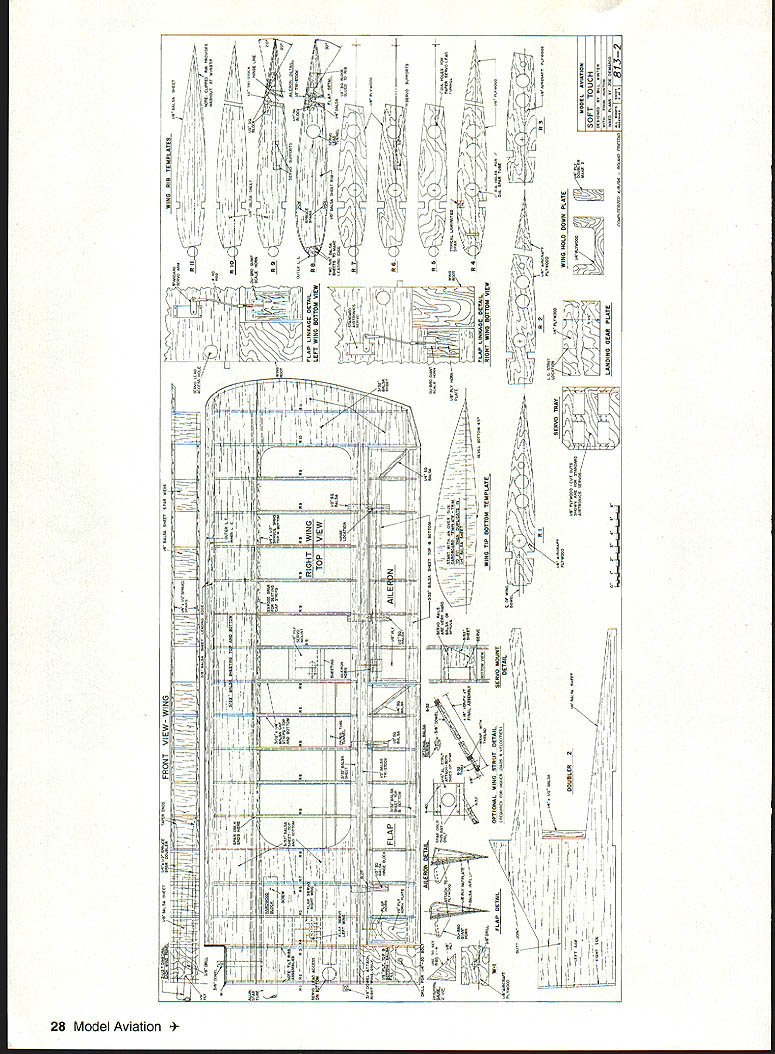
Wing
- Wing-joining system uses a nominal 1" diameter aluminum tube spar.
- Use a tube with .090" minimum wall thickness, hard-drawn if possible. If using lighter-gauge aluminum, fill the tube with a hardwood dowel.
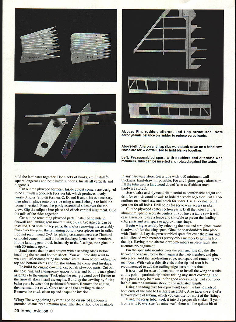
- Stack balsa and plywood rib stock and drill for two 1/8" wood dowels to hold the stacks together. Cut all rib outlines on a bandsaw and notch for spars. Use a Forstner bit for holes where practical. Drill holes for servo wire access in ribs.
- Cut plywood center section parts and drill holes for the aluminum spar to accurate centers.
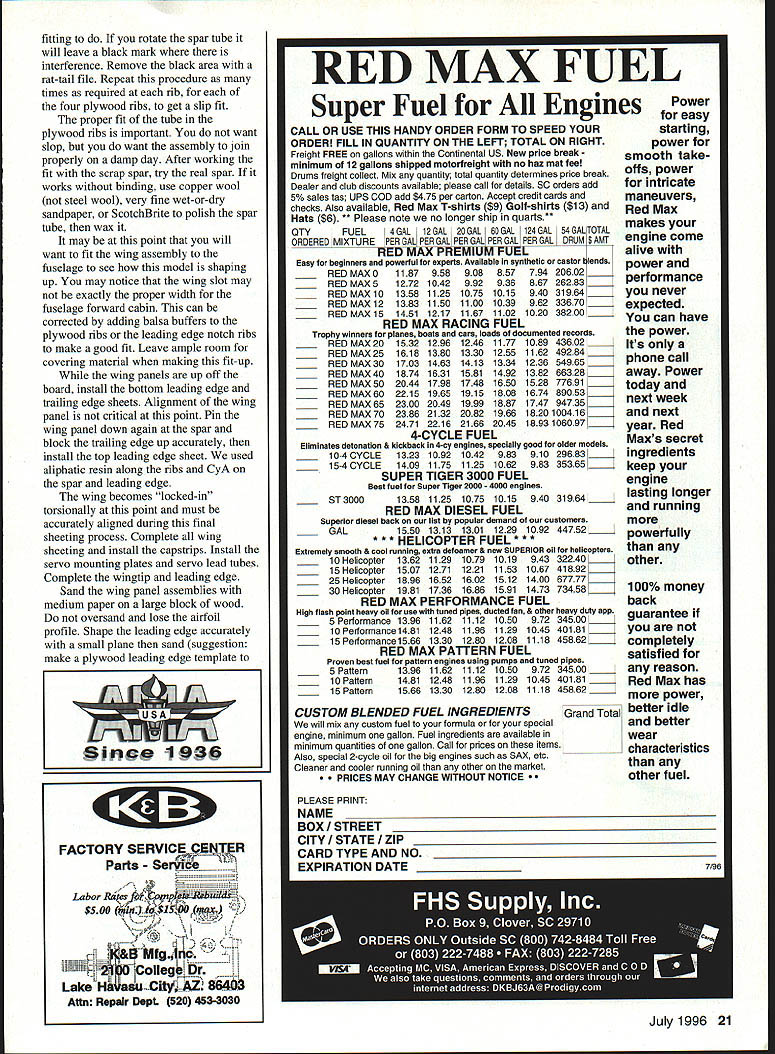
- Select the best straight hardwood for wing spars. Glue spar doublers in place with Titebond. Lay preassembled spars flat over the plans and add indicated web members (every other member beginning from the tip) to facilitate accurate rib alignment.
- Pin the spar subassembly over the plan, slip ribs between spars, rotate them against web members, and glue into place. Add sub-leading edge, rear spar, and remaining web members. Add trailing edge parts with vulnerable rib ends protected.
- Install the spar tube while the panels are still accessible—particularly before any sheet covering. Cut the aluminum tube to length and taper the last 1/2" of both ends to facilitate assembly. Use a scrap tapered tube to work the tube into proper rib sockets and file/polish high spots for a slip fit.
- The fit should have no slop but must not bind in varying humidity.
- Polish spar tube with super-wool, fine wet-or-dry sandpaper, or ScotchBrite, then wax it.
- Fit the wing assembly to the fuselage and verify wing slot width; add balsa shims to ribs or leading-edge notches to make a good fit, leaving room for covering.
- While panels are off the board, install bottom leading and trailing edge sheets. Pin and block the trailing edge up accurately, then install top leading edge sheet.
- Use aliphatic resin along ribs and CyA on spar and leading edge for speed and strength.
- Complete wing sheeting, install capstrips, servo mounting plates, and servo lead tubes. Complete wingtips and finish leading edge shaping with a small plane and sanding.
- Sand wing panels with medium paper on a large block without oversanding the airfoil.
Control Surfaces and Flaps
- Build flaps and ailerons over the plans by pinning down the leading edge, installing ribs, releasing the leading edge (to accommodate curvature), then pinning and gluing ribs to the trailing edge.
- Curved flap sheet: either soak a sheet in hot water and bend around a dowel of the proper radius until dry, or cut a single curved piece and use a shaped balsa block to obtain the proper profile.
- Preinstall hinges and check geometry carefully for smooth operation and correct deflection.
- Empennage: mark parts on the plan and cut with a bandsaw if available. If ribs are slightly long, install end ribs, then sand intermediate ribs to fit using a block over a table edge. Sand all surfaces flat.
- Preassemble sheet covering joints by CyAing edge joints together and presanding flat. Attach sheet to framed parts with Titebond, using CyA through the Titebond at edges for extra adhesion. Weight assemblies until adhesive cures.
Pre-Final Assembly
- Install the fin first with the fuselage flat on the bench; slip the fin into place and trim to make it vertical to the work surface.
- Slip horizontal stabilizer spars in place and slide the stabilizers on. Check and trim so the stabs are horizontal with respect to the bench.
- Fit wing panels together and try them on the fuselage. Check the wing for level relative to the bench. Do not install wing bolts or dowels until covering and finishing are complete.
Covering
- Prototype covering: Sig Koverall.
- Prepare surfaces by sanding with a block, then touch up curves with a sanding pad.
- Apply two heavy coats of 50% thinned clear nitrate dope (use a 1" camel-hair brush). Sand lightly with #150 production paper after each coat.
- Koverall method:
- Get a well-adhered border, then shrink the center.
- Lay the Koverall with grain spanwise. Apply clear nitrate dope around edges of the surface and lay the prepared part onto the Koverall.
- Turn the assembly over and pull edges spanwise to remove wrinkles; dope the edges and wrap them around to the opposite surface to form an overlap.
- To speed hardening of dope on overlaps, set with a film iron at a safe temperature (avoid browning).
- Remove excess dope from the iron with a scraper; brown marks indicate too-high temperature.
- After border dope has set, pass the iron over the entire surface to remove wrinkles; then apply a couple coats of clear nitrate to seal.
- The prototype fuselage was covered with one piece of material: adhered down the center of the bottom, worked around each side to the top, even over the curved cowling.
Finishing
- Prototype finishing sequence:
- Four coats of clear nitrate dope.
- One coat of clear nitrate with talcum.
- Final fine-sanding.
- Four coats of butyrate color.
- Two coats of clear butyrate for gloss topcoat.
- Dope interior around tank and RC equipment for insurance against fuel leaks.
- Use spray finishes (20th Century sprays or similar) for wheel pants and trim colors.
Final Assembly
- Repeat alignment steps from pre-final assembly and glue stabilizer spars in place.
- Wing seating technique:
- Run masking tape along the bottom of the wing seating area where it meets the fuselage and coat the tape with lipstick.
- Seat the wing, remove it, and trim away material marked by lipstick. Repeat until wing seats and is level.
- Prepare hold-down dowel holes:
- Drill forward cabin former with 1/8" diameter to ~1/2" depth.
- Sharpen 1/8" dowels to ~1/2" long with a steep point and insert them (do not glue); let dowels protrude ~1/8".
- Put a dab of lipstick on the dowel points and slide the wing into place to mark final dowel locations.
- Use a 1/8" guide drill then step up to 3/16" for final holes. Install final hold-down dowels.
- Drill and install rear wing hold-down screws and tap for 1/4-20.
- Install struts (as detailed on plans) for engines larger than the K&B 100.
- Install fuel tank, radio system, and full-length antenna.
- Balance the model at the indicated CG (use ballast if necessary). Check side-to-side balance and correct with tip weight as needed. Verify free control movements and specified throw amounts.
Flying
- The Soft Touch has undergone partial structural analysis, incremental load testing, and rigorous flight testing in normal and mild aerobatic operations (loops, rolls, spins, inverted), comparable to utility-type full-scale operation.
- It is possible to exceed design loads with extreme maneuvers (e.g., power dives with rapid pullouts or very rapid control inputs) or when installing a larger engine, which increases velocities. Designs for strut reinforcement of wing and empennage are provided as an option to increase load-carrying capacity.
- Major operational differences for large models:
- Requires more room for takeoffs, turns, and landings; anticipate flying the model farther from yourself than you would a smaller aircraft.
- Mass effects and scale effects become significant. Be prepared for different handling and greater potential for hangar rash.
- Safety:
- Use only wood propellers on the Soft Touch (wood breaks; plastic tends to take).
- Use a checklist, perform range checks, and increase safety procedures in proportion to model size.
- Consider optional struts and reinforcement if flying aggressively or using a larger engine.
- The Soft Touch minimizes many large-model handling surprises with solid flight characteristics and makes a good transition model to larger giants.
Bill Winter 12811 Melville Ln Fairfax, VA 22033
Transcribed from original scans by AI. Minor OCR errors may remain.

