
Softee
Joe Johnson
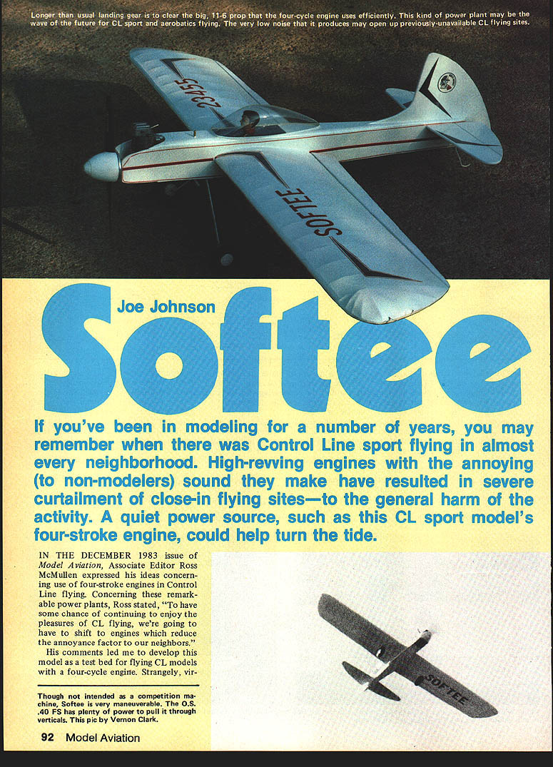
If you've been in modeling for a number of years, you may remember when Control-Line (CL) sport flying was common in many neighborhoods. High-revving two-stroke engines and their noisy bark have curtailed close-in flying sites. A quiet power source, such as a CL sport model's four-stroke engine, could help turn the tide.
In the December 1983 issue of Model Aviation, Associate Editor Ross McMullen noted that, "To have some chance of continuing to enjoy the pleasures of CL flying, we're going to have to shift to engines which reduce the annoyance factor to our neighbors." His comments led me to develop Softee as a test bed for four-cycle CL flying. Virtually no plans or kits available are well suited to the combination of weight and power of a four-stroker, so I designed a simple yet attractive model to match the O.S. .40 FS four-stroke engine.
Design considerations
- O.S. .40 FS engines are considered to produce roughly 60% of the power of a two-cycle engine of the same displacement. I therefore chose what would ordinarily be a largish .25-sized model.
- The extra ounces of engine weight are offset by a smaller fuel tank needed by a four-cycle, so the nose-moment length comes out about average.
- The prototype drawing shows a 2-1/2-oz Fox tank, but that is nearly excessive; a four-stroker will run a very long time on 2 oz of fuel. In practice the O.S. .40 FS behaves more like a .30 two-cycle in power.
- Use the same 10%-nitro Sig fuel commonly used with two-cycles.
- Use wide-bladed props (for example, Rev-Up W, Y, or O) which suit the torque characteristics of a four-cycle. An 11.5-in. wide-bladed prop works well; the model may require 11-in. to 12-in. props.
- Place the fuel tank higher than usual because the carburetor is mounted well above the midline. Some second-generation four-cycle engines have moved the throttle throat nearer the centerline, easing this requirement.
- In my setup Softee's engine runs as well inverted as upright and runs steadily in both positions.
- I would guess a .60 four-cycle would suit currently available 35-size kits—shorten the tank compartment and perhaps alter tank height. Built-up fuselages or side-mounted profiles may need relocated engine bearers.
If you find Softee attractive and want to try four-cycle CL flying, it's delightful to fly—above-average maneuverability and remarkably low sound make the name "Softee" very descriptive.
Construction
Adhesive choice depends on the builder. The prototype was built almost entirely with thick cyanoacrylate (CyA) glue, with 5-minute epoxy used for the engine-mount bulkheads and 30-minute epoxy fillets where needed.
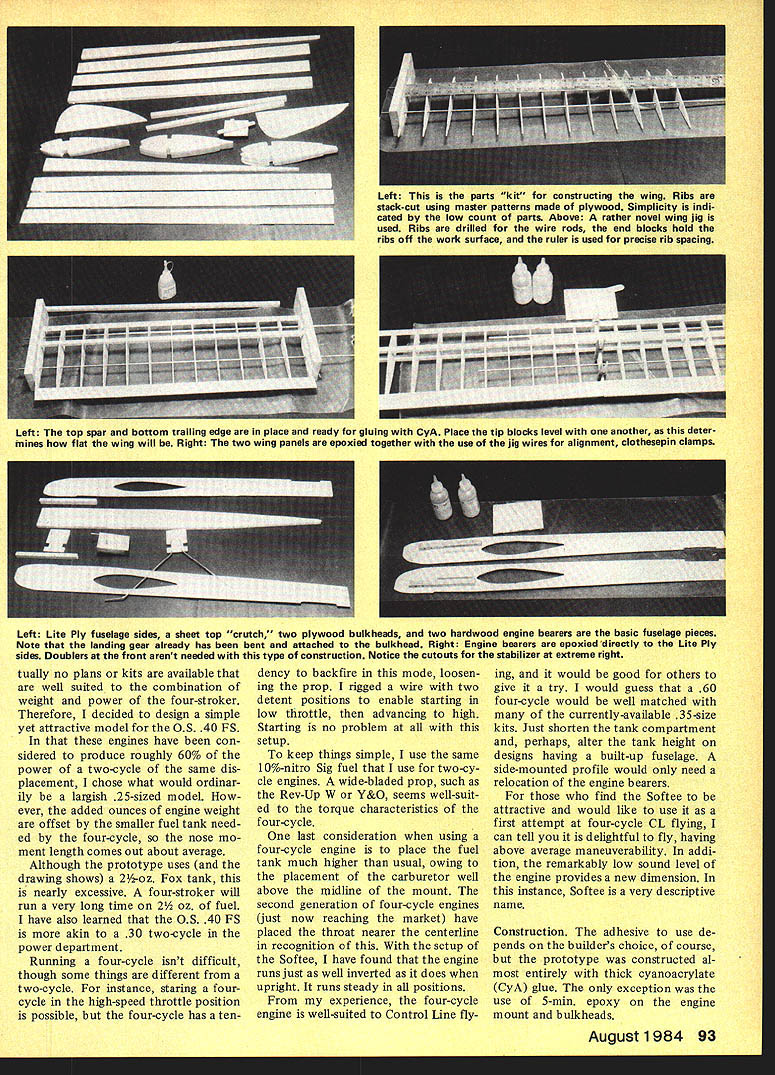
Begin by tracing the plan backed up with carbon paper onto the appropriate wood and cutting the kit-shaped pieces. Wing ribs can be stack-cut from a master pattern; use a plywood or metal template as a guide when appropriate.
As a first step:
- Bend the landing gear.
- Install the bulkhead and drill all required holes.
- Cut the 3/8-in. sheet for the fuselage crutch roughly to shape from the plan.
Wing
The wing can be built conventionally (shimmed level over the drawing) or using a jig technique that simplifies making multiple accurate ribs.
Jig technique (recommended if you have a drill press):
- Rough-cut rib stacks on a Dremel saw, then sand to accurate outlines.
- Using the rib pattern, drill the necessary holes into each stack so the holes are absolutely parallel (a drill press is essential here).
- Drill matching holes into two blocks of 1 x 2-in. (or 1 x 3-in.) pine; mark tops and fronts.
- Thread 3/16-in. music wire through the blocks and slide the ribs onto the wire, keeping rib alignment with your marks.
- Fit the other pine block onto the opposite end and set the spars and trailing edge material using a ruler on a perfectly flat surface. When everything checks for squareness in all directions, glue with thick CyA.
- It can help to tack-glue the bottom spar, remove the wing from the jig, then finish gluing.
- The leading edge strip may be slightly bowed; pin it as needed during assembly.
- Pull the wire out of the panel. Repeat for the opposite wing panel, making a left and a right unit (the right panel is one bay shorter).
- Join the panels at the center section by sliding the wire partway out of one panel and aligning the joint; use cut-off ends of spar material to double the center-section joint.
Bellcrank, lead-outs, and flap/elevator fit:
- Install the bellcrank on the plywood floor.
- With a knife, join the holes in the left panel to create lead-out slots and install the lead-out wires. Do not add wing tips yet—they can be dinged during later work.
- Temporarily install the bellcrank, pushrod, flap horn, and flaps. Make certain everything is free of bind before adding center-section sheeting.
- Note: photos in the original article show an error—the flap horn must be on the top surface to match the elevator setup. Secure the pushrod to the bellcrank and flap horn at this point so alignment will be correct later.
Sand the wing smooth and set it aside while constructing the fuselage.
Fuselage
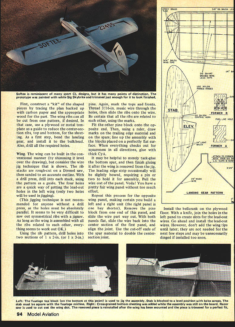
- The top crutch method is used: pin the crutch flat over the drawing and use the extension lines to locate former positions.
- Cut out, sand, and pre-hinge the stabilizer-elevator assembly. If the hinge centerlines are dipped in warmed Vaseline, adhesives and paint won't stick to them.
- Place the assembled stab-elevator unit over the crutch, align carefully, and CyA-glue in place. Use 3/8-in. scrap to ensure the stab-elevator assembly is level.
- Epoxy the Lite Ply engine mounts to the fuselage sides before assembling bulkheads and sides over the crutch with 5-min. epoxy. When dry, blend bulkheads into the sides with 30-min. epoxy fillets.
- Make the nose block and cowl—carve and shape to fit. Install and secure the engine and mount.
- Form the landing gear from 3/32-in. music wire and attach to the fuselage with a 1/32-in. plywood doubler and thread-and-epoxy wraps.
- Allow epoxies to cure. Pull the tail post together and glue with thick CyA.
- Cover the bottom of the fuselage with cross-grain 3/32-in. sheet, leaving the area about 2 in. behind the wing trailing edge open for a hatch (cut the hatch with a razor saw and remove carefully; it will be reattached later).
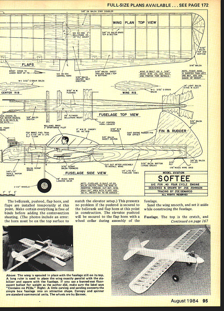
- Seat the wing into the saddle and check alignment: measure under the tips for level and from the wing tips to the tail post for square. When perfectly aligned, CyA-glue the wing to the saddle.
- Install the bellcrank pushrod connections:
- Install a 4-40 solder clevis on the elevator end of the pushrod.
- The other end of the pushrod wire goes into the flap horn and is secured with a wheel collar.
- If using two pieces of 3/32-in. wire joined with a length of 3/32-in. ID brass tube, adjustments can be made before silver-soldering the brass tube in place.
- Using the horn holes shown on the plan will provide approximately 30° of up and down on both the elevator and flaps. Note: both flaps and elevator must be absolutely level when neutral.
- Return and trim the wing hatch to fit, reattach, and complete the fuselage bottom including the tail skid. Remove the assembly from the building board, sand flat sides, and round the top moderately.
- With a large vertical fin, I prefer to cant the entire fin to the right rather than cutting and angling a separate rudder for appearance and simplicity.
- Add wing tips and lead-out tubing. Sand the entire model smooth in preparation for covering.
Covering and finishing:
- The prototype wing and model were covered with World Tex.
- Apply two coats of Sig Skylite filler to the wood, sand, then spray with white Skylite.
- Add accents with MonoKote trim sheets and Sig Stripe-Rite tape. Vinyl letters were used for markings (purchased at an office supply store).
- Wheels used on the prototype were Banner wheels suitable for 1/8-in. wire axles.
Flying
- Balance at the point shown on the plan. With a four-cycle engine, the model may require a slightly longer nose moment—check balance with engine and tank installed.
- The 2-oz. tank shown is adequate for long flights with a four-stroke.
- With 1 oz. of lead glued to the right tip and the fin offset as shown, the model has excellent line tension without adverse yaw.
- Softee flies comfortably on .015-in. wire by 60-ft. lines; it has also been flown on 70-ft. lines.
- Flight characteristics:
- Flies faster than anticipated, yet corners are smooth and well controlled.
- Exhibits little tendency to jump or bump; good for windy days.
- Long landing gear was necessitated by the need for large props (11–12 in.). The "stalky" gear gives exceptional smoothness on the ground in takeoffs and landings.
- Noise:
- Noise level is very low, with little of the objectionable "bark" of two-stroke engines.
- In a congested residential area, neighbors reported no complaints; one neighbor remarked, "I wish some of the lawn mowers in this neighborhood were as quiet."
- Four-strokers have the potential to reopen nearby playgrounds and parking lots to Control-Line flying.
Notes and recommendations
- Running a four-cycle isn't difficult, but some things differ from two-cycle operation:
- Starting at high throttle is possible but the engine tends to backfire; this can loosen the prop.
- I rigged a two-detent wire on the prop/throttle to start at low throttle and advance to high—this makes starting trouble-free.
- Use wide-bladed props suited to four-cycle torque characteristics.
- Consider a .60 four-cycle for 35-size kits, shortening tank compartments and altering tank height as needed.
- Designs with built-up fuselages or side-mounted profiles may require relocation of engine bearers.
Softee is a splendid sport stunter and a good introduction to four-cycle CL flying—quiet, attractive, and pleasant to fly.
Transcribed from original scans by AI. Minor OCR errors may remain.

