
Solder Wiring Tool
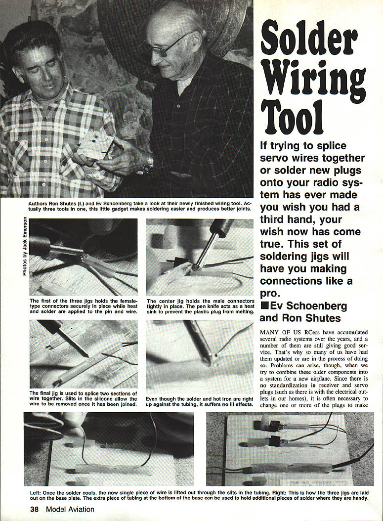
If trying to splice servo wires together or solder new plugs onto your radio system has ever made you wish you had a third hand, your wish has come true. This set of soldering jigs will have you making connections like a pro.
- Ev Schoenberg and Ron Shutes
Many RC modelers accumulate several radio systems over the years, and often need to combine older components into a new airplane. Because receiver and servo plugs are not standardized, it is frequently necessary to change one or more of the plugs. Soldering tiny wires and connectors can be frustrating and time-consuming, so we developed a simple, inexpensive jig that acts like a third hand. The jig is made largely from heat-resistant silicone fuel tubing and, when complete, functions as three tools in one: a splicer, a single-pronged female-connector jig, and a double-pronged male-connector jig.
Required materials
- A baseplate of 1/16‑in. aluminum or 1/8‑in. plywood, three to four inches square.
- One piece of 1/4‑in. medium‑size silicone fuel tubing, about 4‑1/2 in. long.
- One piece of large‑diameter silicone fuel tubing, about 1‑1/2 in. long.
- A teaspoon of baking soda (make sure it’s baking soda, not baking powder).
- A bicycle spoke or suitably sized music wire (for forming guides).
- Cyanoacrylate (CA) glue.
- A sharp #11 razor blade or hobby knife.
- Soldering iron (about 25 W recommended), solder, heat‑shrink tubing, and a pen knife to act as a heat sink.
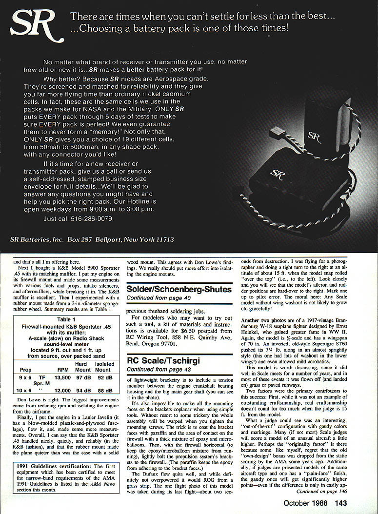
Construction
- Cut the medium 4‑1/2‑in. tube into four pieces: one 2‑in. piece, two 1‑in. pieces, and one 1/2‑in. piece. These pieces form the three jigs.
- Make the splicing tool:
- Insert a bicycle spoke or music wire all the way through the 2‑in. tubing. Use wire that slips through easily but is still reasonably snug.
- Using a sharp #11 blade, cut a 3/16‑in. wide wedge out of the center of the tubing along the wire side. The wire will guide the straight horizontal part of this cut.
- With the wire still inserted and the cutout facing up, glue the tubing to the baseplate by applying CA along the bottom edge of the tubing. Dust a small amount of baking soda on the CA to speed cure and strengthen the bond. After the glue cures, remove the wire spoke.
- Starting at the cutout, carefully cut exit slits partway along the upper wall of the tubing, slicing outward to each end. These slits allow the finished splice to be removed.
- Position the other tubing pieces to form the connector jigs:
- Glue one 1‑in. tube parallel to and about 2 in. from the splicing tool to form the single‑prong connector holder.
- Glue the short large‑diameter tubing (the 1/2‑in. piece cut from the larger tube) approximately 3/8 in. in front of and at right angles to the wedge end of that 1‑in. tube. The space between these two tubes should match the length of the connector housing you plan to solder.
- For the double‑prong male connector jig, glue the 1‑in. slotted tubing in line with a 1/2‑in. piece of large tubing acting as a backstop. Space them to fit the width of the male connector and position them about 3 in. up from the bottom of the baseplate.
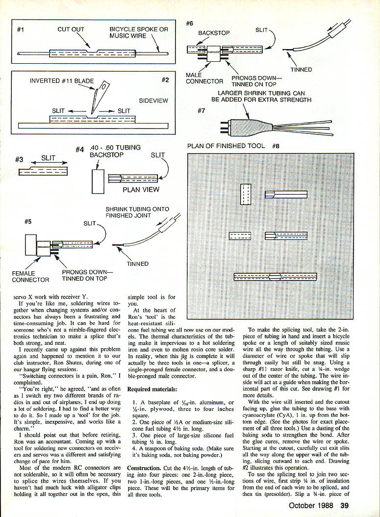
Using the splicing tool
- Strip and tin the ends of the two wires to be joined. Slip a small piece of heat‑shrink tubing onto one wire before soldering.
- Feed the wires into the splicing tool from the ends so the tinned ends meet side‑by‑side in the wedge cutout. The silicone tubing holds the wires in position.
- Use a 25‑watt soldering iron to touch the tinned wire ends and add solder until the joint is fully fused.
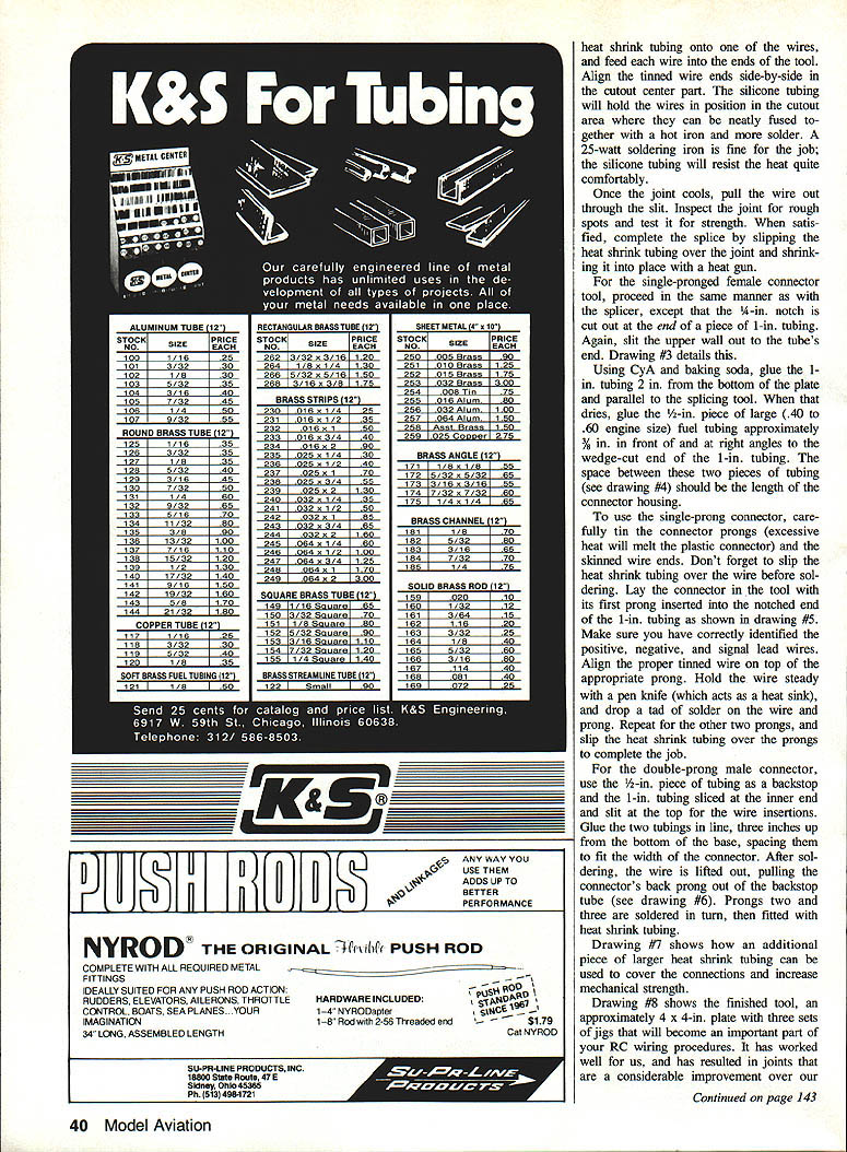
- Allow the joint to cool, then pull the wire out through the slit. Inspect and test the joint for strength. Slide the heat‑shrink tubing over the joint and shrink it in place.
Single‑pronged female connector jig
- Cut a 1/4‑in. notch in the end of one 1‑in. tube, then slit the upper wall outward to the tube’s end for wire access.
- Glue this 1‑in. tube to the base as described above, and mount the short piece of larger tubing as a support/backstop in front of the wedge.
- Slip heat‑shrink onto the wires before soldering. Lay the connector in the jig with its first prong inserted into the notched end. Identify positive, negative, and signal leads and align the correctly tinned wire on top of each prong.
- Hold the wire steady with a pen knife (it acts as a heat sink and protects the plastic), and drop a small amount of solder on the wire and prong. Repeat for the remaining prongs. After soldering, slide heat‑shrink tubing over the prongs and shrink.
Note: Excessive heat will melt plastic connector housings. Tin both wire ends and connector prongs before joining.
Double‑pronged male connector jig
- Use the slotted 1‑in. tubing for prong/top support and the 1/2‑in. larger tubing as a backstop glued in line.
- Lay the male connector prongs down into the slotted tube with the back prong against the backstop. Tin the top side of each prong with the prongs facing down.
- Solder prongs sequentially. After soldering, lift the wire out; the connector’s back prong will pull out of the backstop tube, freeing the assembly. Fit heat‑shrink tubing over each joint as needed.
Finishing and tips
- A pen knife or other metal tool held against the connector acts as a heat sink and protects plastic from excess heat.
- A 25‑watt soldering iron is usually adequate; the silicone tubing resists the iron and molten solder.
- Larger heat‑shrink tubing can be used to cover multiple prongs and increase mechanical strength.
- The finished tool is roughly a 4 x 4‑in. plate with three jigs and makes soldering connectors and splices neat, strong, and much less frustrating than holding tiny parts by hand or with alligator clips.
For modelers who want a ready kit of materials and instructions, a kit was available for $6.50 postpaid from RC Wiring Tool, 858 N.E. Quimby Ave., Bend, Oregon 97701.
Transcribed from original scans by AI. Minor OCR errors may remain.

