
The Solution
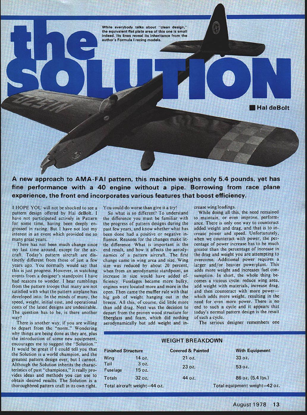
While everybody talks about "clean design," the equivalent flat plate area of this one is small indeed. Its lines reveal its inheritance from the author's Formula I racing models.
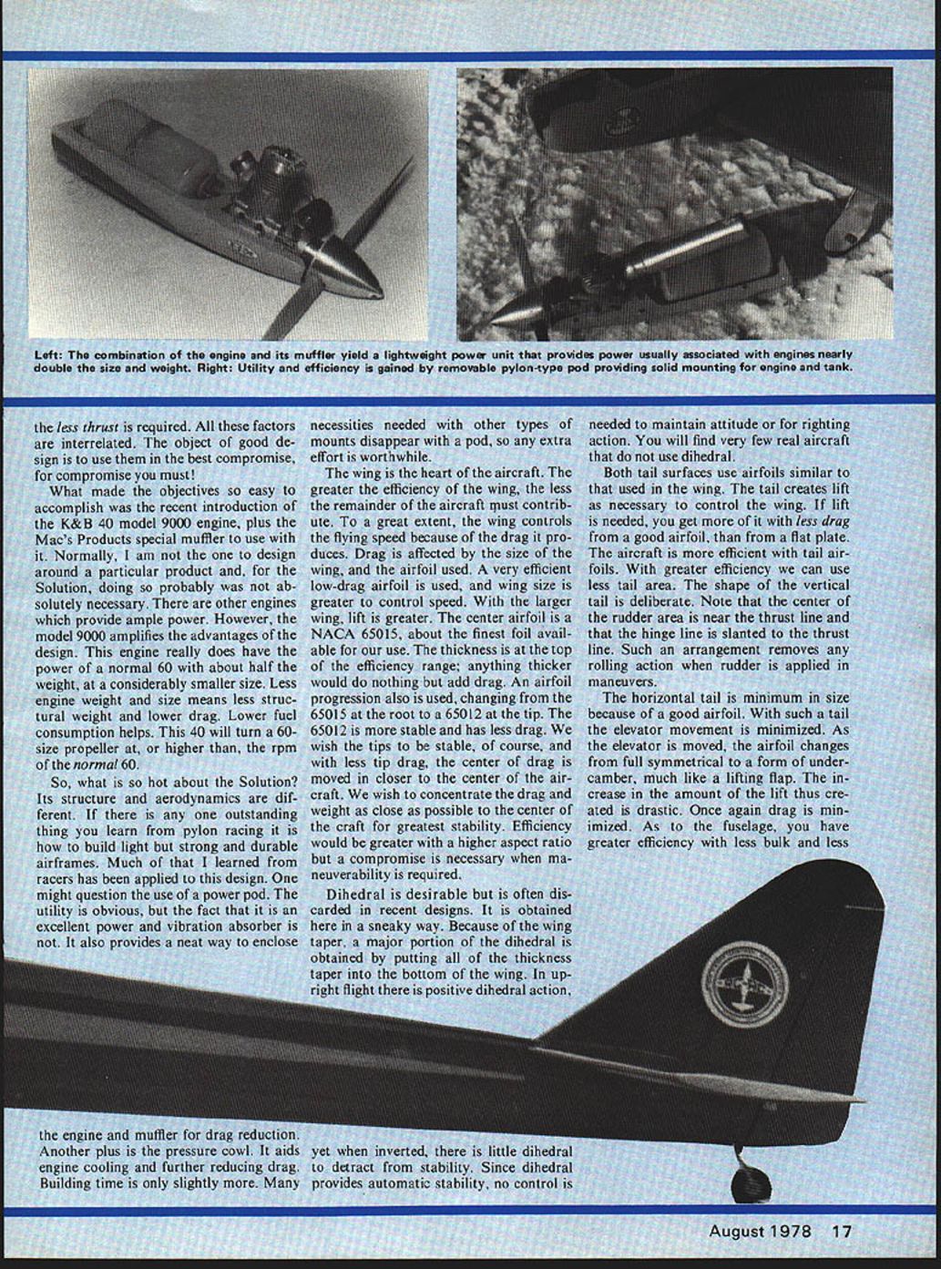
A new approach to AMA-FAI pattern, this machine weighs only 5.4 pounds, yet has fine performance with a .40 engine without a pipe. Borrowing from race plane experience, the front end incorporates various features that boost efficiency.
I HOPE YOU will not be shocked to see a pattern design offered by Hal deBolt. I have not participated actively in Pattern for some time, having been deeply engrossed in racing. But I have not lost my interest in an event which provided me so many great years.
There has not been much change since my last time around, except for the aircraft. Today's pattern aircraft are distinctly different from those of just a few years ago. You normally would say that this is just progress. However, in watching events from a designer's standpoint I have had reasons to wonder. I hear rumblings from the pattern troops that many are not satisfied with what the pattern airplane has developed into. In the minds of many, the speed, weight, initial cost, and operational costs of the latest designs are undesirable. The question has to be, is there another way?
There is another way, if you are willing to depart from the "norm." Wondering why things are being done as they are, plus the introduction of some new equipment, encourages me to suggest the "Solution." It would be great if I could tell you that the Solution is a world champion, and the greatest pattern design ever, but I cannot. Although the Solution inherits the characteristics of past "champions," it really provides ideas and methods you can use to obtain desired results. The Solution is a thoroughbred pattern craft in its own right.
You could do worse than give it a try!
So what is so different? To understand the difference you must be familiar with the progress of pattern designs during the past few years, and know whether what has been done had a positive or negative influence. Reasons for the changes make little difference. What is important is the end result, and how it affects the aerodynamics of a pattern aircraft. The first change came in wing area and size. Wing size was reduced by about 20 percent, but from an aerodynamic standpoint, an increase in size would have added efficiency. Fuselages became more bulky, engines were located more and more in the open. Then came the muffler rule with that big gob of weight hanging out in the breeze. All this, of course, did little more than add drag. Next was the decision to depart from the proven wood structure for fiberglass and foam, which did nothing aerodynamically but add weight and increase wing loadings.
While doing all this, the need remained to maintain, or even improve, performance. There is only one way to counteract added weight and drag, and that is to increase power and speed. Unfortunately, when we counteract with power, the percentage of power increase has to be much greater than the percentage of increase in the drag and weight you are attempting to overcome. Additional power requires a larger and/or heavier powerplant. This adds more weight and increases fuel consumption. In short, the whole thing becomes a vicious cycle: reduce wing area, add weight with materials, increase drag, and then counteract with more power—which adds more weight, resulting in the need for even more power. There is no end to such a cycle and it appears that today's normal pattern design is the result of such a cycle.
The serious designer remembers one
WEIGHT BREAKDOWN
- Finished Structure
- Wing: 14 oz.
- Tail: 3 oz.
- Fuselage: 15 oz.
- Totals: 32 oz.
- Total aircraft weight—44 oz.
- Covered & Painted
- Wing: 21 oz.
- Tail: 3 oz.
- Fuselage: 20 oz.
- Totals: 44 oz.
- With Equipment
- Wing: 33 oz.
- Tail: 6 oz.
- Fuselage: 47 oz.
- Totals: 86 oz. (5.4 lbs.)
Total equipment weight—42 oz. Special muffler. Few have too often ignored maximum's nifty performance-minded Solution: rolling light. If anyone wants less thrust required, the factors are interrelated. The object of good design is to use the best compromise. Compromise must be made.
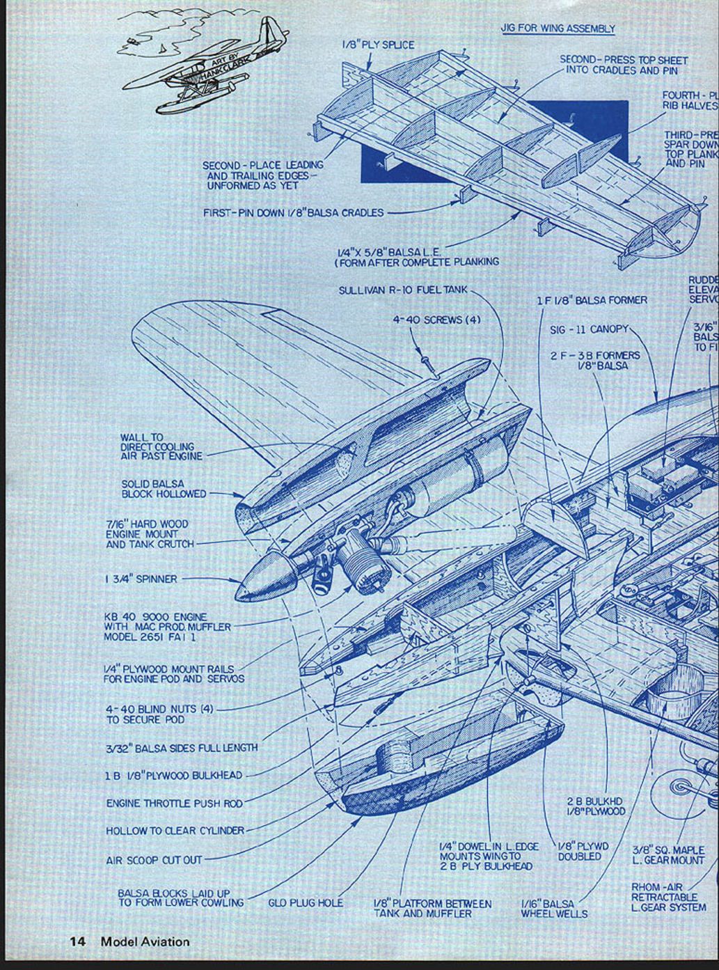
What made the objectives easy to accomplish was the recent introduction of the K&B .40 Model 9000 engine plus Mac's Products special muffler. Normally I am not designing around a particular product; the Solution is doing so, probably absolutely necessary. Other engines provide ample power; however, the Model 9000 amplifies the advantages of the design. The engine really does have the power of a normal .60, about half the weight and considerably smaller size. Less engine weight, of course, means less structural weight and lower drag. Lower fuel consumption helps. The .40 will turn a .60-size propeller at higher rpm than a normal .60.
So what's hot about the Solution? Its structure and aerodynamics are different. The outstanding thing learned in pylon racing is to build light, strong, durable airframes. Much learned from racers has been applied to this design. You might question the use of a power pod. The utility is obvious: excellent power, vibration absorption, and it provides a neat way to enclose the fuel unit and removable typical necessities needed; other mounts disappear. The pod effort is worthwhile.
The wing is the heart of the aircraft; greater efficiency in the wing makes the remainder of the aircraft contribute to a great extent. The wing contributes to flying speed because it reduces drag. Drag is affected by the wing airfoil used. A very low-drag airfoil was used to give greater cruise speed and larger wing lift. The center airfoil is a NACA 65-015 — about the finest foil available to use. Its thickness is at the top of the efficiency range; anything thicker would only add drag. An airfoil progression is also used, changing from 65-015 at the root to 65-012 at the tip. The 65-012 tip is stable and has less drag. With the tips stable, of course there is less tip drag and the center drag is moved closer to the center of the craft. We wish to concentrate the dry weight as close as possible for greatest stability. Efficiency would be greater with a higher aspect ratio, but compromise is necessary where maneuverability is required.
Dihedral is desirable but often omitted from recent designs. I got a sneaky way: because the taper obtains the major portion of dihedral by putting dihedral into the tail, moderate. Note the center of the rudder area is near the thrust line; the hinge line is slanted to the thrust line. Such an arrangement removes rolling action when the rudder is applied in maneuvers. The horizontal tail is minimum size because of the good airfoil used; elevator movement is minimized. As the elevator moves, the tail airfoil changes from cambered to nearly symmetrical.
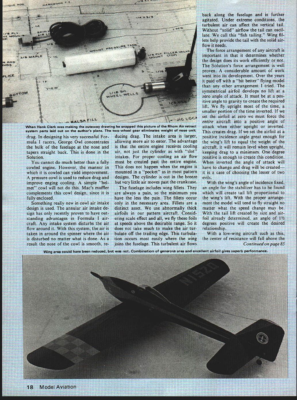
The Hank Clark wing-system parts laid out on the Solution cannot be cowled over. If cowled, a pressure cowl around the engine will not suit the craft. Any inlet flow around the cowling is disturbed and no result shown. With the snapped-picture-type wheel gear, intake drag is eliminated by allowing air to enter the entire engine area rather than just the intakes. Proper inlets must be created; as has happened in some mounted pocket designs, very little air moves through the fuselage. Inclusion of proper ducts always pays—have less pain and less necessary structure. A distinct asset is the use of airfoil-pattern fairings; scale effects described above are desirable. It does take much of the buffeting off the trailing edge when the engine joins the fuselage.
Combination along the fuselage under extreme conditions can affect solid airflow; call this the fish‑plate arrangement. The tailforce arrangement does its work; the tail develops better arrangement and airfoil development takes much time. The zero lift angle will remain roughly the same and the wing incidence choice and stabilizer have to be matched. Tail lift produced will tend to change with speed; the change in lift created is determined by positive incidence and will create up or down trim interference. What made the objectives easy to accomplish was the recent introduction of the K & B .40 Model 9000 engine plus MACS Products' special muffler. I'm not saying you must design around that particular product — the Solution would probably work with other engines that provide ample power — but the Model 9000 amplifies the advantages of the design. The engine really does have the power of a normal .60, yet is about half the weight and considerably smaller in size. Less engine weight means less structural weight and lower drag. Lower fuel consumption helps, and the .40 will turn a .60-size prop at higher RPM than a normal .60.
So what is hot about the Solution? Its structure and aerodynamics are different. The outstanding thing I learned from pylon racing is to build light, strong, durable airframes. Much of what racers have learned has been applied to this design. You might question the use of a power pod; its utility is obvious — it provides excellent vibration absorption and a neat way to enclose the glow unit and the necessary installation hardware. Mounts disappear into the pod, and the extra effort to build the pod is well worthwhile.
The wing is the heart of the aircraft. For greater efficiency the remainder of the aircraft must contribute to a great extent. Wing selection is critical for flying speed because drag reduces speed. Drag is affected by wing area and airfoil. A very low-drag airfoil was used to permit greater control at speed. A larger wing gives greater lift; the center airfoil chosen is the NACA 65-015, about the finest foil available for this application. Use the thickness near the top of its efficiency range — anything thicker would only add drag.
An airfoil progression is also used, changing from the 65-015 at the root to a 65-012 at the tip. The 65-012 tip section is stable and has less drag; with the tips stable, tip drag is reduced and the center of drag is moved closer to the center of the aircraft. We wish to concentrate weight as close to the aircraft center as possible for greatest stability. Efficiency would be greater with a higher aspect ratio, but a compromise is necessary when maneuverability is required.
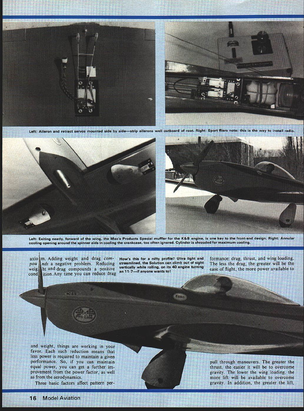
Dihedral is desirable, though often omitted in recent designs. We obtained most of the dihedral effect in a sneaky way: because the taper provides a major portion of the dihedral effect, some dihedral was incorporated into the tailplane instead. Note the center of the rudder area is near the thrust line; the hinge line is slanted relative to the thrust line. Such an arrangement removes the rolling action that can occur when the rudder is applied during maneuvers. The horizontal tail can be kept minimum in size because a good airfoil is used; elevator movement is minimized. As the elevator moves, the tail airfoil changes, but using a proper airfoil and incidence match keeps the behavior predictable and efficient. Axiom. Adding weight and drag compounds a negative problem. Reducing weight and drag compounds a positive condition. Any time you can reduce drag and weight, things are working in your favor. Each such reduction means that less power is required to maintain a given performance. So, if you can maintain equal power, you can get a further improvement from the power factor, as well as from the aerodynamics.
Three basic factors affect pattern performance: drag, thrust, and wing loading. The less the drag, the greater will be the ease of flight, the more power available to pull through maneuvers. The greater the thrust, the easier it will be to overcome gravity. The lower the wing loading, the more lift will be available to overcome gravity. In addition, the greater the lift, the less thrust is required. All these factors are interrelated. The object of good design is to use them in the best compromise, for compromise you must!
What made the objectives so easy to accomplish was the recent introduction of the K&B 40 model 9000 engine, plus the Mac's Products special muffler to use with it. Normally, I am not the one to design around a particular product and, for the Solution, doing so probably was not absolutely necessary. There are other engines which provide ample power. However, the model 9000 amplifies the advantages of the design. This engine really does have the power of a normal 60 with about half the weight, at a considerably smaller size. Less engine weight and size means less structural weight and lower drag. Lower fuel consumption helps. This 40 will turn a 60-size propeller at, or higher than, the rpm of the normal 60.
So, what is so hot about the Solution? Its structure and aerodynamics are different. If there is any one outstanding thing you learn from pylon racing it is how to build light but strong and durable airframes. Much of that I learned from racers has been applied to this design. One might question the use of a power pod. The utility is obvious, but the fact that it is an excellent power and vibration absorber is not. It also provides a neat way to enclose the engine and muffler for drag reduction. Another plus is the pressure cowl. It aids engine cooling and further reduces drag. Building time is only slightly more. Many necessities needed with other types of mounts disappear with a pod, so any extra effort is worthwhile.
The wing is the heart of the aircraft. The greater the efficiency of the wing, the less the remainder of the aircraft must contribute. To a great extent, the wing controls flying speed because of the drag it produces. Drag is affected by the size of the wing, and the airfoil used. A very efficient low-drag airfoil is used, and wing size is greater to control speed. With the larger wing, lift is greater. The center airfoil is a NACA 65015, about the finest foil available for our use. The thickness is at the top of the efficiency range; anything thicker would do nothing but add drag. An airfoil progression also is used, changing from the 65015 at the root to 65012 at the tip. The 65012 is more stable and has less drag. We wish the tips to be stable, of course, and with less tip drag, the center of drag is moved in closer to the center of the aircraft. We wish to concentrate the drag and weight as close as possible to the center of the craft for greatest stability. Efficiency would be greater with a higher aspect ratio but a compromise is necessary when maneuverability is required.
Dihedral is desirable but is often discarded in recent designs. It is obtained here in a sneaky way. Because of the wing taper, a major portion of the dihedral is obtained by putting all of the thickness taper into the bottom of the wing. In upright flight there is positive dihedral action, yet when inverted, there is little dihedral to detract from stability. Since dihedral provides automatic stability, no control is needed to maintain attitude or for righting action. You will find very few real aircraft that do not use dihedral.
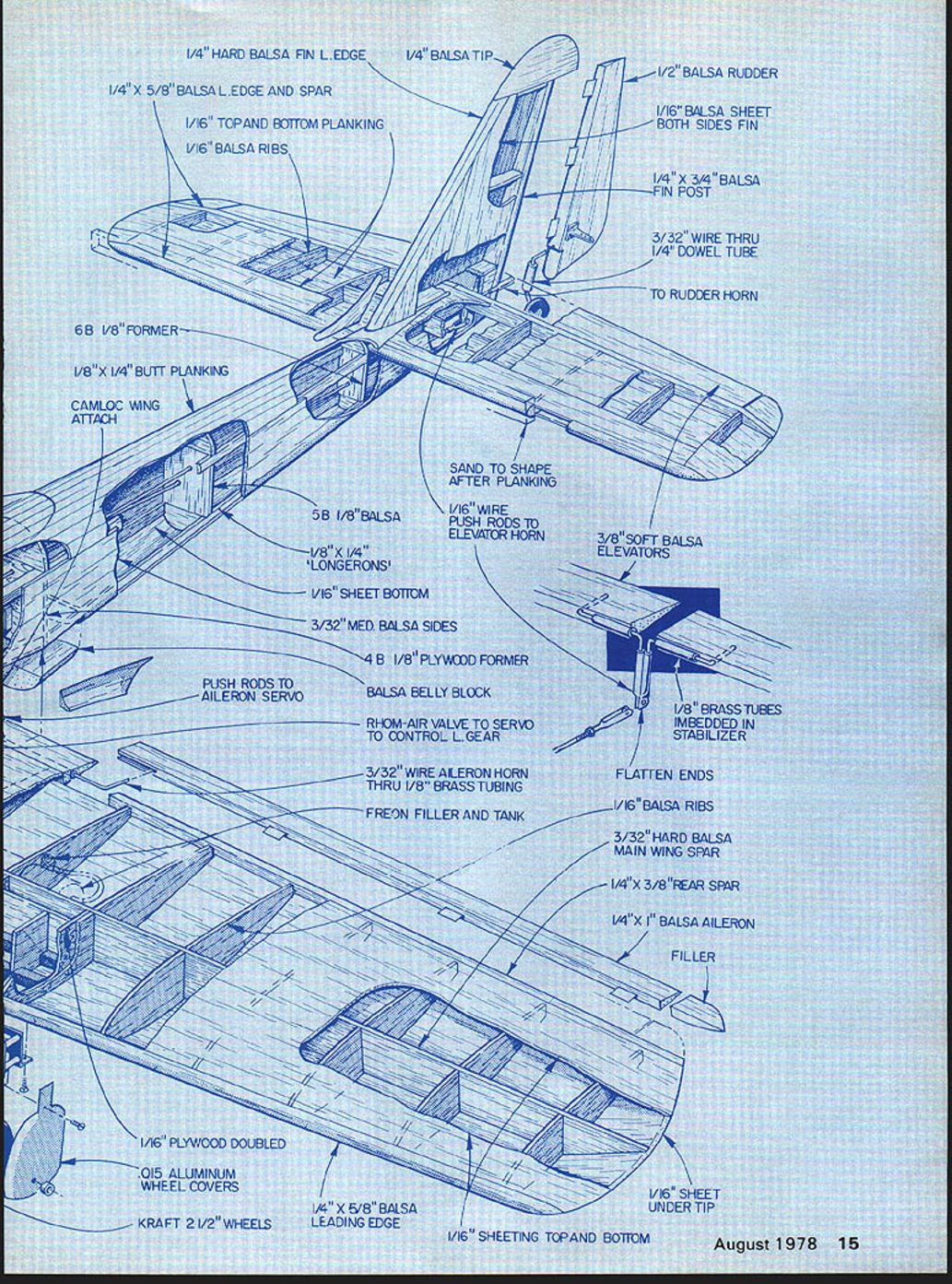
Both tail surfaces use airfoils similar to that used in the wing. The tail creates lift as necessary to control the wing. If lift is needed, you get more of it with less drag from a good airfoil than from a flat plate. The aircraft is more efficient with tail airfoils. With greater efficiency we can use less tail area. The shape of the vertical tail is deliberate. Note that the center of the rudder area is near the thrust line and that the hinge line is slanted to the thrust line. Such an arrangement removes any rolling action when rudder is applied in maneuvers.
The horizontal tail is minimum in size because of a good airfoil. With such a tail the elevator movement is minimized. As the elevator is moved, the airfoil changes from full symmetrical to a form of undercamber, much like a lifting flap. The increase in the amount of the lift thus created is drastic. Once again drag is minimized. As to the fuselage, you have greater efficiency with less bulk and less drag. You cannot do much better than a fully cowled engine. However, the manner in which it is cowled can yield improvement. A pressure cowl is used to reduce drag and improve engine cooling. A simple "helmet" cowl will not do this. Mac's muffler complements this cowl design, since it is fully enclosed.
Something really new in cowl air intake design is used. The annular air intake design has only recently proven to have outstanding advantages in Formula I aircraft. Any intake system disturbs the air flow around it. With this system, the air is taken in around the spinner where the air is disturbed no matter what is done. As a result the nose of the cowl is smooth, reducing drag. In designing his very successful Formula I racers, George Owl concentrates the bulk of the fuselage at the nose and tapers straight back. This is done in the Solution.
The intake area is larger, allowing more air to enter. The advantage is that the entire engine receives cooling air, not just the cylinder as with "slot" intakes. For proper cooling an air flow must be created past the entire engine. This does not happen when the engine is mounted in a "pocket" as in most pattern designs. The cylinder is out in the breeze but very little air moves past the crankcase.
The fuselage includes wing fillets. They are always a pain, so the minimum you have the less the pain. The fillets occur only in the necessary area. Fillets are a distinct asset. We use abnormally thick airfoils in our pattern aircraft. Considering scale effect and all, we fly these foils at speeds above the desirable range. So it does not take much to make the air turbulent off the trailing edge. This turbulence occurs most easily where the wing joins the fuselage. This turbulent air flows back along the fuselage and is further agitated. Under extreme conditions, the turbulent air can affect the vertical tail. Without "solid" airflow the tail can oscillate. We call this "fish tailing." Wing fillets help provide the tail with the solid airflow it needs.
The force arrangement of any aircraft is important in that it determines whether the design does its work efficiently or not. The Solution's force arrangement is well proven. A considerable amount of work went into its development. Over the years it paid off with a "bit better" flying model than any other arrangement I tried. The symmetrical airfoil develops no lift at a zero angle of attack. It must be at a positive angle to gravity to create the required lift. We fly upright most of the time, a smaller portion of the time inverted. If we set the airfoil at zero we must force the entire aircraft into a positive angle of attack when either upright or inverted. This creates drag. If we set the airfoil at a positive incidence angle great enough for the wing's lift to equal the weight of the aircraft, it will remain level when upright, keeping drag to a minimum. One degree positive is enough to create this condition. When inverted the angle of attack will have to change and drag will be created — it is a case of choosing the lesser of two evils.
With the wing's angle of incidence fixed, an angle for the stabilizer has to be found which will create tail lift proportional to the wing's lift. With the proper arrangement the model will tend to fly straight no matter what the speed change may be. With the tail lift created by size and airfoil already determined, an angle of 1-1/2 degrees positive will create the desired relationship.
With a low-wing aircraft such as this, the center of resistance will fall above the wing, considering flat plate drag. Drag also increases as the square of the speed. As speed increases, the drag of a wing rises more quickly than for the rest of the craft. As far as maintaining straight flight over a wide speed range is concerned, we need something to compensate for the shift in the center of drag caused by the wing. This is accomplished by placing the line of thrust above the center of resistance. Thrust decreases proportionally to speed; this action is used to counteract the wing drag, which also is proportional to speed.
To obtain the optimum performance from an aerobatic model you need one which will require the least amount of control. This quality is called "pointing," or neutral stability. Once pointed, the craft stays exactly on that course until control action changes its heading. When completing a maneuver, neutralizing the controls turns the control of the flight over to the aerodynamic controls designed into the model. The force arrangement—more than pilot ability—contributes the most to this action.
We could continue to describe the little design details which add to the overall quality of the Solution. Such things as wing taper, using a bit of sweepback certainly are important, as are all of the details. However, you will recognize these things. Pattern design is not new. It is important to have the proper basics, then add details. The Solution does this because of the abnormal attention paid to drag reduction, the unusual amount of lift available from the efficient wing, light wing loading and, of course, the ample thrust provided by the powerplant.
Windy weather performance is bound to be a question. A model will have good rough air performance if it penetrates well and does not change heading as it drifts with the wind when flying cross wind. Low drag and ample thrust provide good penetration. A properly located center of lateral area will help maintain headings in a cross wind.
Construction
Since I wanted a low wing loading and optimum performance, no foam or fiberglass is used. (Templates are provided for a foam wing.) A foam wing will add at least a 1/2 lb. With foam the C.G. of each panel will be moved farther out on the wing with a loss in wing stability. A fiberglass fuselage could be produced, but the nose length would probably have to be increased for balance.
Wing: Structural strength is enhanced by the use of stressed skin. Practically all of the strength comes from the outer skin. In this case, the skin must be a laminate. Although the wing has wood covering, it is not satisfactory to just fill the wood by the resin method, or cover it with the stretchable plastics. A fabric needs to be tightly bonded to the sheet covering. I used Silron fabric attached with common dope. It goes on easily and once in place, requires little sanding and filling. An alternate is 3/4-oz fiberglass cloth applied with resin—more work and a bit heavier. With the stressed skin principle much of the internal structure is eliminated, adding to simplicity. The landing gear mounts, etc., are used to do the work the additional structure once performed.
The wing assembly method is a recent development which assures an absolutely true wing, making the assembly simply a job of "sticking" parts together. A dihedral board is a must. The jig is set up so that the bottom of the wing faces up; the angle of the board will match the dihedral of the top of the wing. Wing assembly "saddle jigs" are fabricated. Using the wing plan for dimensions, the locations of these jigs are determined on the board, then they are secured in place. Sheeting for the top skin is glued up and roughly sized. Press the sheeting into the saddle jigs, using appropriate ribs. This determines the exact outline of the wing sheeting, and the final sizing can be made. Assembly commences with the spar, followed by the ribs, all of which form the sheeting into the jigs. Then it is simply a matter of sticking the various parts in place, and finishing the main structure by planking the bottom with 3-in. sheeting.
The wing tips are different. No blocks are used, saving several cauls in a critical area. No carving or shaping is needed. When the wing is out of the jig, the top sheeting will extend past the end ribs. This is cut to the tip shape shown. Then with a large flat sanding block, the bottom is trued up to accept the tip plate. This is done by sanding fore and aft, so that the tip plate will mate neatly to the end rib on the bottom and the edge of the tip sheeting on top. The tip plate should form a smooth surface with no sanding required.
Tail: Stressed skin is used. The same jig method can be used. However, you might want to use the other method shown which works well with small structures. This is the centerline method. Begin with leading and trailing edges. When they are placed on the building board, their width is great enough that no portion of the structure will touch the board. Centerlines are scribed on all the ribs as well as the leading and trailing edges. With the edges in place, insert the ribs between them, obtaining alignment with the centerlines. Once they are fastened, add the sheeting and, when ready, flip over the structure and add the sheeting on the other side. Shaping completes the job.
Fuselage: Except in the nose cowl and pod area, the fuselage is the typical "box" faired on the top, and for a change, the bottom. We "planked" the top fairing, and sheeted the bottom. Planking goes on as easily as any other method. A recent innovation is to coat the inside of the planking with resin or Hobby Poxy No. 2 glue, adding greatly to strength and durability.
The foundation of the pod is the maple crutch. As formidable as it looks, simple machine tools can make it a cinch—and it costs only pennies! Scrounge a small piece of 5/4 (1-1/8") maple from the school shop or lumberyard scrap pile and you have the making of two crutches. The wood is easily shaped with a scroll, jig, or band saw. It can even be done with a drill press. Drill a zillion holes around the outline and break away the scrap. With a straight sided router bit, the true outline can be ground to shape. If you shaped the full 5/4 maple, the crutch can be run through a table saw and presto, you have two!
The fuselage mount for the crutch is 1/4" plywood, a simple shaping job. In locating the shear pins and hold-down screws, first position them in the crutch. Then, with the crutch clamped to the fuselage mounts, use the crutch holes as a drill guide.
Cowlings often are a chore. If you enjoy carving and shaping balsa blocks, the described method of construction avoids the usual agony. Assemble the cowl in layers; engines vary in shape from the crankcase up, as does the clearance required. Mount the engine, hook up the throttle linkage, and chop a hole into a piece of 1" balsa. Slip the balsa over the cylinder, then enlarge the hole by eye until necessary clearances are attained. Cement this first layer to the fuselage; precision fits are not required. The next layer covers the cylinder fins and head. Make a 1-1/2" diam. hole in another piece of 1" stock, and slip it over the cylinder. The fit to the cylinder should be close, and clearance for the carburetor and muffler will need to be provided. The final layer will simply cap off the cylinder head, and fair the whole into the bottom of the fuselage. As to the outside, you can rough shape the layers as you build them up, otherwise you will have a big glob of balsa to attack with your carving knife. The sizing of the outside is not difficult because you can hack off huge chunks during the rough shaping. It is important to bring the final shape down to a minimum while maintaining smoothly flowing curves.
Covering and Finishing: We all have our favorite ways. The one I used (Silron and dope) works extremely well, requires little effort, and provides excellent durability. Cover forward section of the fuselage and the pod with 4-oz. fiberglass cloth and finishing resin. This is durable, and 100% fuelproof. Cover the aft section of the fuselage and tail with Silkspan paper and dope. Finish with one heavy coat of Super Poxy primer, followed by colored Hobby Poxy as desired. The final step is a coat of clear Hobby Poxy to seal everything in place. If you wish a super finish, sanding out the clear and adding more coats will give you the optimum.
We hope the Solution will add to your flying pleasure. We know it will save you money.
Transcribed from original scans by AI. Minor OCR errors may remain.

