
Sopwith Dolphin
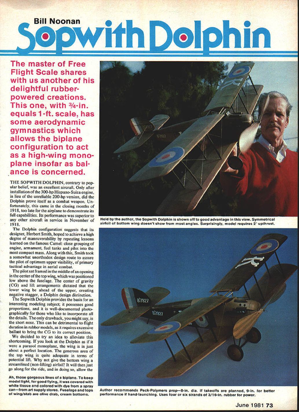
Contrary to popular belief the Sopwith Dolphin was not an excellent aircraft only after the installation of the 300-hp Hispano-Suiza engine in lieu of the unreliable 200-hp version did the Dolphin prove itself a combat weapon. Unfortunately, it came in the closing months of 1918—too late for the airplane to demonstrate its full capabilities. Its performance was superior to other aircraft in service in November 1918.
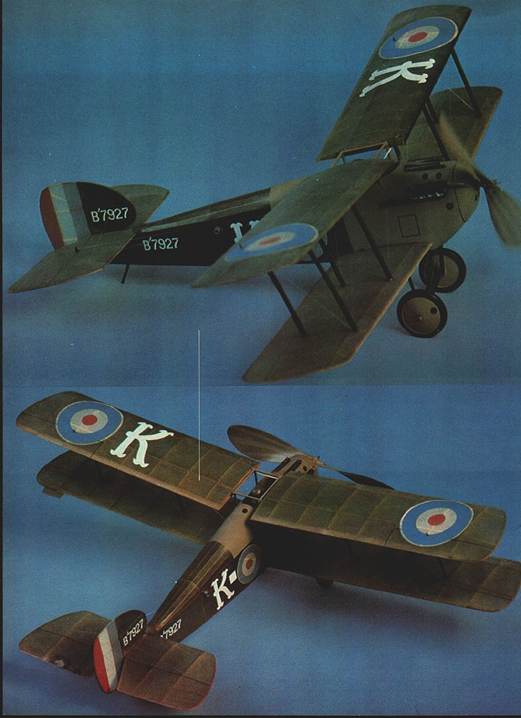
The Dolphin's configuration suggests its designer, Herbert Smith, hoped to achieve a high degree of maneuverability, repeating lessons learned with the famous Camel: close grouping of engine, armament, fuel tanks and pilot into a compact mass. To assure the pilot optimum upper visibility—the primary tactical advantage in aerial combat—Smith took a somewhat unorthodox design route. The pilot sat framed in the middle opening of the center top wing, which was positioned low above the fuselage center of gravity. The lift arrangements dictated the lower wing be ahead of the upper, creating a negative stagger. This distinctive arrangement is one of the Dolphin's design signatures.
The Sopwith Dolphin provides the basis for an interesting modeling subject. It possesses good proportions and is well documented photographically, making it easy to incorporate details. A drawback for rubber-powered models is the short nose, which can be detrimental to flight duration because it requires excessive ballast to bring the CG to its correct position. To alleviate this, the author tried a Dolphin parasol monoplane: the top wing sits nearly in the perfect location and its generous area provides adequate lift. Giving the bottom wing a streamlined non-lifting airfoil lets it go along for the ride, preserving the gorgeous lines of the biplane while keeping the model light and good flying.
Cover with white tissue colored with aerosol dye available at art supply stores. Fuselage tops, wing and stabilizer olive drab; cream bottoms.
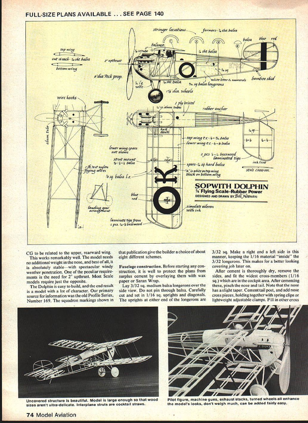
The related upper rearward wing position works remarkably well—the model needs no additional weight in the nose and is absolutely stable with spectacular windy-weather penetration. The peculiar requirements call for 2° upthrust. Most scale models require just the opposite. The Dolphin is easy to build and the end result is a model with a lot of character. Primary source information was the old Profile Series No. 169; the squadron markings shown there give the builder a choice of about eight different schemes.
Fuselage construction
Before starting construction, protect plans by overlaying them with wax paper or Saran Wrap. Build the fuselage sides over the side view as follows:
- Lay 3/32" sq. medium balsa longerons over the side view. Do not pin through the balsa.
- Carefully cut and set 1/16" sq. uprights and diagonals. The uprights at either end of the longerons are 3/32" sq.
- Make a right and a left side, keeping the 1/16" material inside the 3/32" longerons—this makes a better looking covering job later.
- After cement is thoroughly dry, remove the sides and fit the widest cross-members (1/16" sq.) in the cockpit area.
- After cementing these, pinch the nose and tail. Note the nose has a slight taper.
- Cement tail post and add nose cross pieces, holding together with spring clips or lightweight adjustable clamps.
- Fill in other cross members and complete the uncovered structure. Wood sizes may be adjusted to suit.
Add 1/16" sheet lower wing root filler and filler pieces to accommodate rubber anchor tubing (see plans). Cut turtleback formers from light 1/16" sheet balsa. Cement in place and file stringer notches with a small file or folded sandpaper.
Stringers may be sliced 3/32" x 1/32" hard balsa or a similar-size basswood; basswood has the advantage of not sagging between formers. Note stringers run from bulkhead 2 to 4, with 1-ply bristol (card stock) covering the turtleback immediately behind the cockpit to simulate metal covering as on the real machine.
The sculptured cowlings surrounding the cockpit and engine portion are carved from soft balsa block and hollowed to about 1/8" wall thickness. This component requires care to fit accurately, as it must be drilled to accept bamboo cabane struts, gun cavities, and circular vent holes. The opening immediately below the valve cover projection may be cut, or painted flat black later.
The sides of the nose are filled with 1/16" sheet balsa; the bottom "chin" is 1/4" soft balsa, slightly rounded forward of the landing gear struts. Cut nose block from hard balsa block or laminate from 1/4" sheet balsa. Fit 1/16" inside diameter (ID) aluminum tubing or a nylon thrust button for the prop shaft, which should be .045" wire. Incorporate 2° upthrust.
Exhaust pipes may be made of soda straws or fashioned from balsa. Valve cover and fairings are balsa. The two Vickers guns are made by wrapping paper around a dowel and cementing at the seam. After removing from the dowel, fill the front end with a small balsa disc and add a short muzzle. Give these details at least two coats of sanding sealer before final coloring.
Turn wheels from medium balsa using a small lathe or by chucking the rough wheel disc in a drill motor: cement a 1/4" hardwood dowel about 1" long in the center of the balsa disc, mount in the chuck, contour with sandpaper, cut the dowel off flush with the wheel sides, and drill a 1/32" hole for the axle. The tail skid is fashioned from a bamboo sliver set in a scrap balsa block and cemented at the tail post.
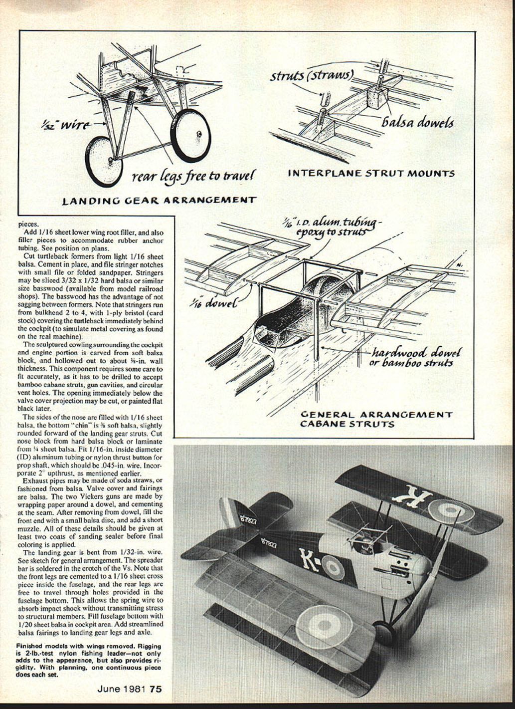
Interplane struts may be made from cocktail straws. A pilot figure, machine guns, exhaust stacks and turned wheels enhance the model's looks and add little weight.
Landing gear arrangement
Add 1/16" sheet where required for gear mounts and fittings. The landing gear is bent from 1/32" wire. The spreader bar is soldered in the crotch of the Vs. Note that the front legs are cemented to a 1/16" sheet cross piece inside the fuselage and the rear legs are free to travel through holes provided in the fuselage bottom. This allows the spring wire to absorb impact shock without transmitting stress to structural members. Fill the fuselage bottom with 1/20" sheet balsa in the cockpit area and add streamlined balsa fairings to landing gear legs and axle.
Finished models often have removable wings. Rigging is 2-lb.-test nylon fishing leader—not only adds to the appearance but also provides rigidity. With planning, one continuous piece does each set.
On the author's model, wings are removable and retained with rubber bands to absorb impact shock; the weight penalty is slight. The four wing panels are provided with 1/16" I.D. aluminum tubing cemented at root ribs and running parallel with spar sides. These tubes mate with similar tubing cemented transversely across the fuselage: two supported by cabane struts and two across the cockpit bottom for the lower wings. Hardwood dowel of 1/16" dia. and about 1" long is forced into each of the eight tube ends, forming a plug-in capability. In case of broken dowels, they may be pushed out of the tubing. Allow for dihedral when cementing tubing in place.
Wing construction
Ribs and spars
- Cut 32 ribs from 1/20" medium balsa—16 for the top wing, 16 for the bottom (streamlined) wing.
- Pin each batch together and sand carefully to assure uniformity and airfoil accuracy.
- Scribe spar locations with a sharp, soft pencil, making sure these are 90° from the rib chord. Carefully file notches for the four 1/16" sq. spars.
- Ribs are vulnerable to breakage at the little web that separates the top spar from the bottom; after removing pins, apply cyanoacrylate glue to the web of individual ribs to strengthen them.
Assemble the ribs over the plans, fitting them to the two lower spars. Carefully force the top spars in place. Position leading and trailing edges and check the assembly for alignment; apply cyanoacrylate glue to joints.
Root ribs on the lower panels should be slightly angled to accommodate dihedral. All four wing panels have hard balsa filler pieces cemented between the top and bottom spars from the root rib to the second rib—this strengthens the vulnerable area and forms a base for the aluminum tubing plug-in.
Tips and struts
The wing tips are made by laminating two pieces of 1/32" x 3/32" basswood (soaked in hot water) around thick (1/8") cardboard or balsa forms cut to tip contour. Wax the edges of the form with a candle or crayon before applying white glue to the basswood; hold in place overnight with pins. The white glue tends to seep out; the waxing facilitates removal of the tip from the form. After the tip is thoroughly dry, trim and cement in place. Pinch the top and bottom 1/16" sq. spars where they butt the tips and apply cyanoacrylate glue.
Cement the 16 interplane strut bases in place: they should position on the top surface of the bottom wing and on the bottom surface of the top wing. After covering, drill these to accept 5/64" balsa dowels about 1/4" long, which become the straw interplane strut mounts.
Carefully contour leading and trailing edges to conform to the airfoil, fairing in basswood tips. Finish all frame members with 400-grit sandpaper.
Tail surfaces
The stabilizer is constructed by laying hard 1/16" sq. balsa over the plans where spars and ribs are located. Position 1/8" sq. and 1/16" x 1/4" balsa leading and trailing edges. Apply cyanoacrylate glue to all joints. The 1/16" "ribs" are built up by applying 1/16" x 3/32" pieces (glued on the 1/16" edge) running full chord from leading to trailing edge. Trim these pieces to give a lifting airfoil and to strengthen the framework where it abuts the spar. Tips are laminated in the same manner as the wing tips. See the plans for the typical stabilizer cross section.
Build the rudder in the same way as the stabilizer, but make the airfoil symmetrical.
Finishing
Cover the Dolphin with white tissue adhered to the frame. Apply adhesive to the undercamber of the top wing. Diluted white glue is recommended to adhere tissue, though clear dope or other adhesives may be used as preferred.
Color scheme follows British practice of 1918: olive drab fuselage and top surfaces of wings and stabilizer; cream undersides for the entire aircraft. On some Dolphins, the metal portion of the turtleback and the fuselage forward of the cabane struts were painted light gray, as were the wheels. Identifying letters and numerals were white, except for the "K" on the underside of the lower right wing, which was black. The rudder was striped red, white and blue, with the blue stripe closest to the fin.
After covering, shrink the tissue with a fine spray of rubbing alcohol; it evaporates rapidly and minimizes the possibility of loosened glue joints.
The author colored the model with "Spray Mark," an aerosol dye available through art supply stores. It is transparent, very light, and resists fading. Its main shortcoming is water solubility; it requires at least two coats of clear dope to seal it effectively.
Mask roundel areas with frisket (a thin translucent vinyl-like material with adhesive backing). Roundels and rudder stripes may be cut from colored tissue and doped onto the white tissue.
Interplane struts: use strong, light cocktail straws painted gray. Because most straws are polyethylene and resist most glues, roughen the inside with a small rat-tailed file before gluing (epoxy preferred). Flatten slightly to a streamlined section.
Rigging: thread 2-lb.-test nylon fishing leader in a small needle and stitch the rigging in place, piercing the straw strut bases. With care, one continuous piece of thread can be used for each set of wings. Rigging not only adds character but unifies the wing assemblies.
If using removable wings, install small hooks at the leading and trailing portions of both top and bottom wings so rubber bands can hold the wings in place. These stretch between the top panels approximately at the spars and under the cockpit on the lower wings.
Finish detailing with ink-ruled lines for aileron, rudder and stabilizer separations.
Flying
- For ROG (rise off ground) use an 8-in. Peck-Polymers prop; a 9-in. prop gives significantly better performance.
- Power the model with four lubed strands of 3/16" rubber for pleasant, no-trauma flights. Six strands will give much more climb but require more critical adjustment.
- Rubber length should be about twice the distance from the aluminum tube to the nose. With four strands you should be able to pack in at least 1,600 turns.
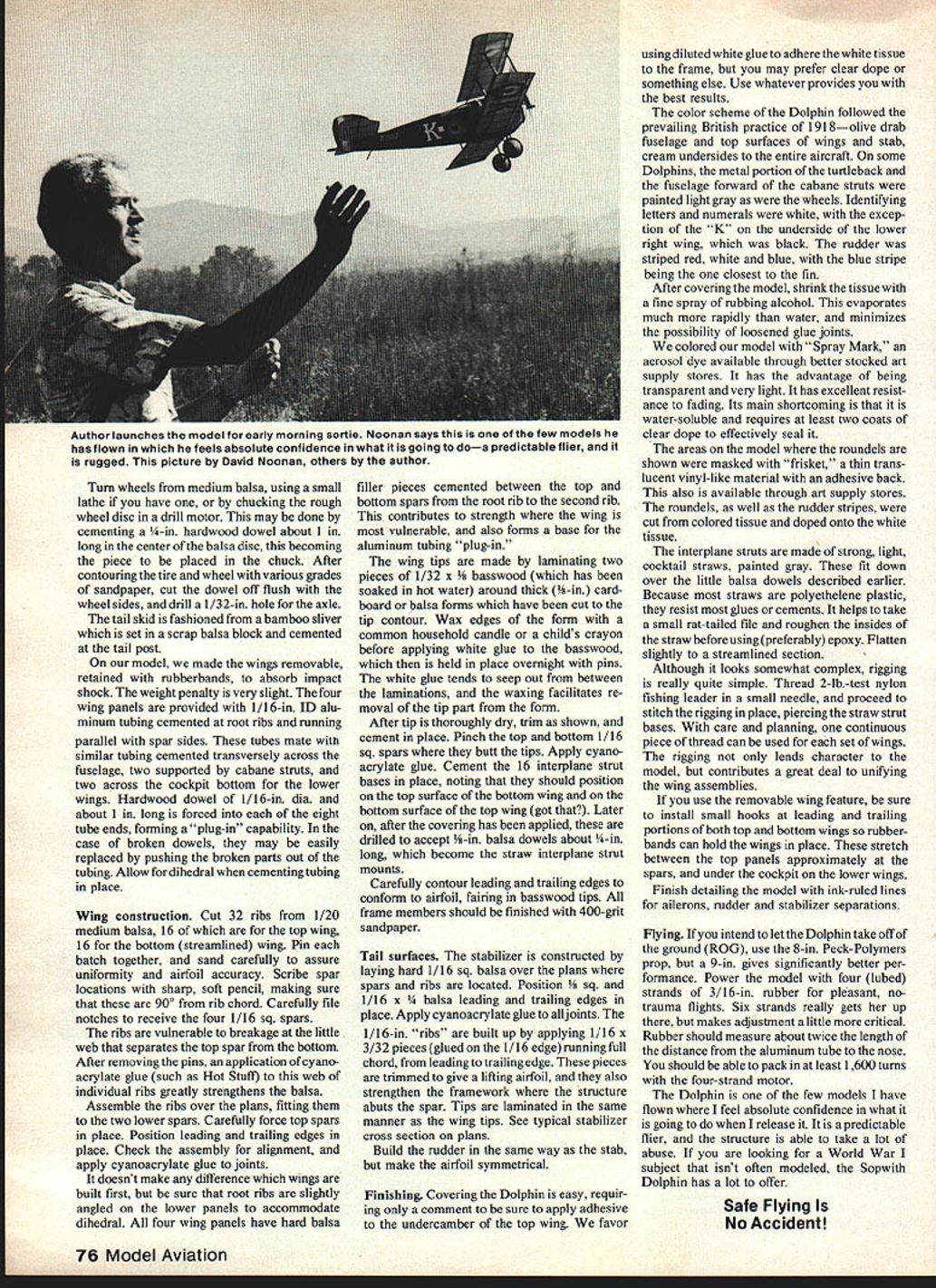
The Dolphin is a predictable flier and its structure can take a lot of abuse. It is one of the few models the author felt absolute confidence in upon release. If you are looking for a World War I subject that isn't often modeled, the Sopwith Dolphin has a lot to offer.
Safe Flying Is No Accident!
Transcribed from original scans by AI. Minor OCR errors may remain.

