
Sorta Pitts
By Brad Shepherd
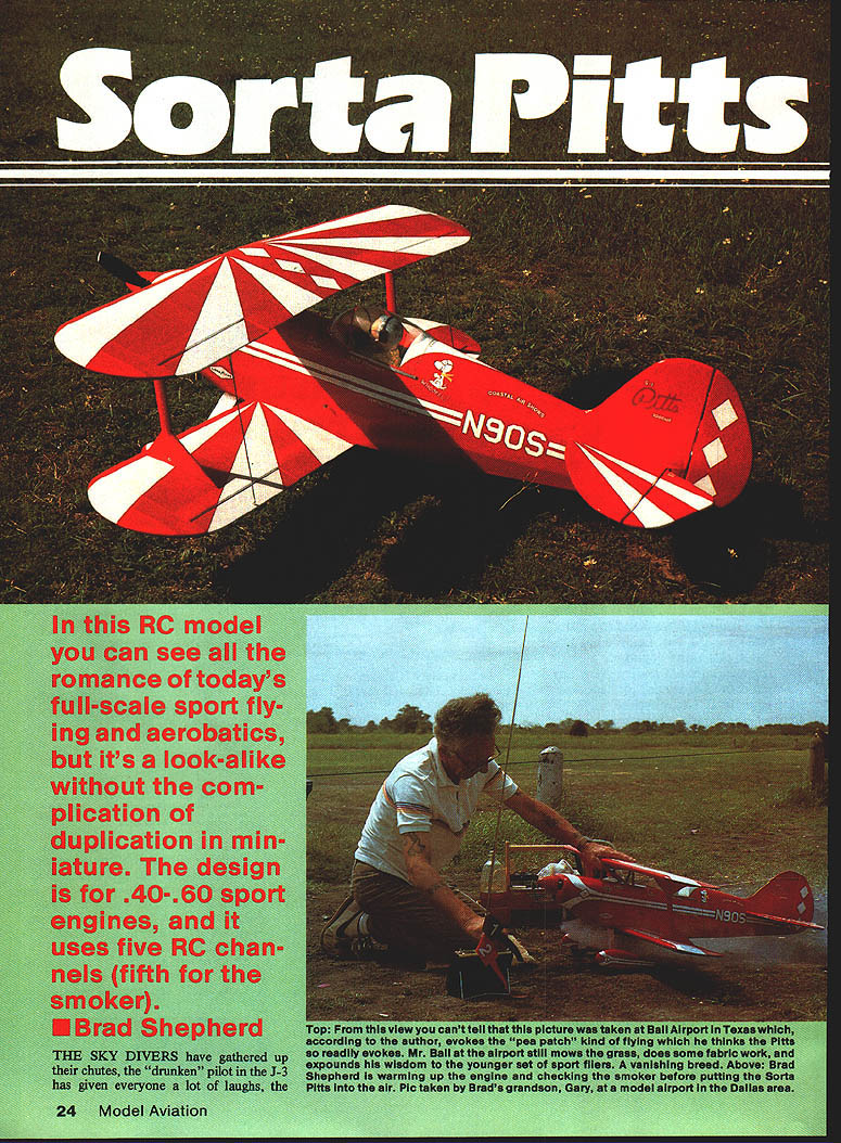
In this RC model you can see all the romance of today's full-scale sport flying and aerobatics — a look-alike without the complication of full-scale duplication in miniature. The design is for .40–.60 sport engines and uses five RC channels (the fifth for the smoker).
It is about 3:00 in the afternoon at the local air show when the pulsing sound of 180 horses fills the air as the small red object on the far end of the runway begins to move. Faster now, it lifts off staying two feet above the runway. With smoke billowing from the exhaust stacks, it pulls up and rolls inverted as it passes the crowd. Pushing outside to a vertical climb, a half roll, and then a hammerhead stall, it comes boring down, pulling up a few feet from the runway into a loop with a snap roll on top.
Who among us does not get their "jolly juices" flowing as one of these little biplanes paints a ballet in the sky? Since 1946, when Betty Skelton started thrilling people with an aerobatic routine in her Little Stinker (the first plane that Curtis Pitts built), this little biplane has been at or near the top of the aerobatics heap, with several World Championships to its credit.
Contrary to some opinions voiced in the past, the new breed of monoplane has not replaced the Pitts in competition aerobatics. Seven out of the nine planes on the U.S. Aerobatics Team at the 1984 World Championships in Hungary were Pitts airplanes, with Debbie Rihn winning bronze in Women's Individual and Harold Chappel, flying his Pitts, helping Henry Haigh and Kermit Weeks capture the Team Trophy.
Although I made no attempt to scale this model precisely, it looks like a Pitts in the air — which is what I set out to achieve. I used reference photos and general dimensions intended to yield a good flying model for .40 to .60 power.
After the initial flights I found the center of gravity (CG) slightly aft and the model had a built-in left turn. Shifting the landing gear forward and adding nose weight brought the CG to the correct location. Adjusting the aileron setup eliminated the turning tendency. I then shimmed the lower wing: as built it had about 1° of positive incidence, and I added 1/64-in. shims one at a time until the incidence reached 0° and the bad habits were ironed out.
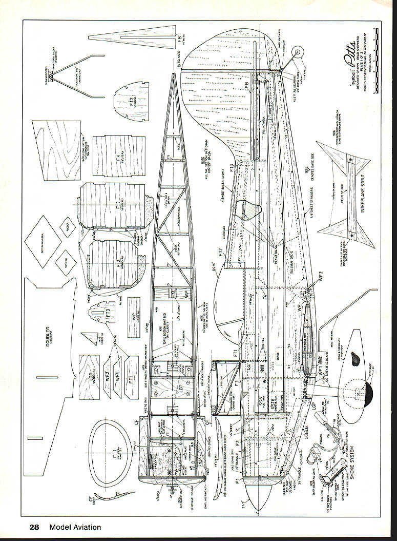
At the CG shown on the plans the model has these surface movements:
- Elevator: 1/2 in. up and down
- Ailerons: 3/8 in. up and down
- Rudder: as much movement as you can get without interfering with the elevator
With 726 sq. in. of wing area and a loading of 18 oz./sq. ft. with a .40 engine installed, it does all that is asked of it except four-point vertical maneuvers. With a .60 engine and additional reinforcement of the spars, it becomes a real honker. The smoke system shown on the plans has worked well; I increased density by stuffing the muffler with copper wool from an unraveled car battery ground cable.
If this interests you, study the pictures and plans together to clear up any areas that might seem difficult.
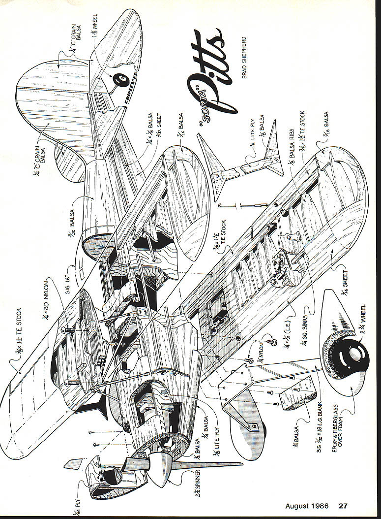
Construction
Wings
The wings are pretty much standard; build them first to set the cabane strut blocks properly.
- Use the plans' notes and details; horn locations and interplane strut approximations will depend on the individual model. The plywood-core strut lengths may vary from the prototype, so don't assume the plan length is exact.
- Make a jig for rib placement. Use 1/16-in. shims under the bottom spar and a piece of 1/4-in. sq. positioned at the leading edge and trailing edge sheeting to hold the ribs in place.
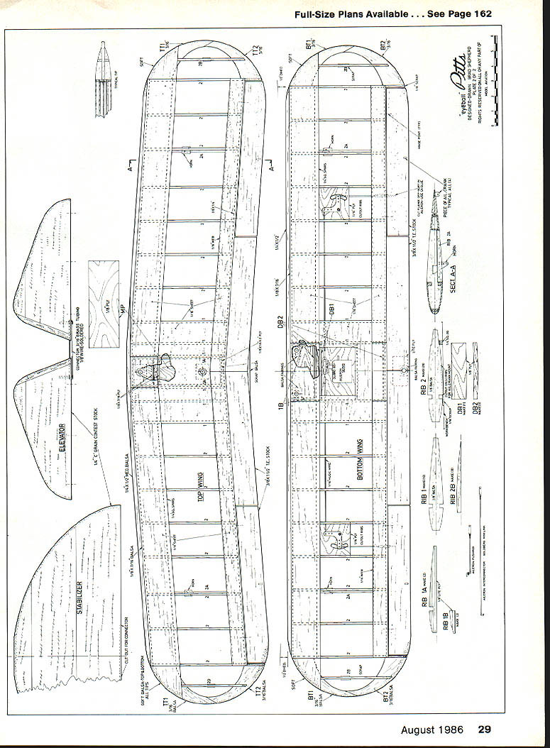
- Top wing: build flat as one piece.
- Bottom wing: build in two halves, then join.
- Pin spars and shims in place and glue all ribs. Note the cutouts in the ribs where dihedral bends occur.
- Glue the 1/8 x 1/4-in. rear spar to the edge of the 1/4 x 1-in. trailing edge sheet, then glue both onto the ribs, butting the spar against the rear of the ribs.
- Glue the 1/8 x 7/16-in. leading edge spar to the front of the ribs and sand to contour.
- Add leading edge sheeting. Make sure sheeting joints are over the centers of the ribs per the plans.
- Glue 1/4-in. plywood ribs to the top of the wing and add ply spar pieces.
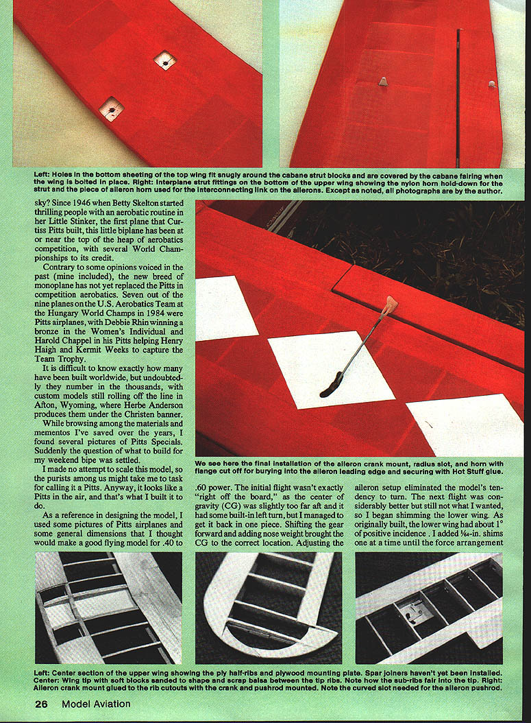
- Turn panels over, glue 1/16-in. webbing and bottom sheeting. Raise the bottom wing with 1/4-in. blocks at each tip, then glue DB1 and the three DB2 pieces in place.
- Draw centerlines on outboard #2 ribs and glue tips in place, keeping them 90° to the ribs. Glue scrap 1/8-in. sub-ribs to wing tips and 2A ribs and soft block to the top and bottom of the tip leading edges.
- Sand the leading edge sheeting with a long block, then glue 1/4 x 1/2-in. balsa leading edge in place.
- Cut 3/8 x 1/2-in. trailing edge stock to length, sand to fit against rear spar, and glue with cyanoacrylate (CYA).
- Trim about 1/16-in. from aileron leading edges so they fit flush; sand to a double taper as shown on Sec. A-A of the drawing.
- Glue ply piece MP to the top of the wing using epoxy. Add 1B ribs to the bottom wing and glue 1/4-in. ply mounting plates to the ribs generously with epoxy.
- Glue 3/16-in. ply aileron bellcrank mounts to rib cutouts on the four #2 ribs. Install 1/16-in. music wire pushrods, leaving excess at the center for servo hookup.
- Glue ply plate at bottom trailing edge of lower wing and top center section sheeting. Set wings aside.
Aileron Bellcrank and Mounts
- Install aileron bellcrank mounts and glue top spars into place.
- Ensure bellcrank mounts are glued in the correct rib cutouts and that pushrods run cleanly to the center for servo hookup.
Fuselage
- Sides are straight lines except for lower wing recesses. If 6-in. sheet balsa is not available, edge-glue two 3-in. sheets for the sides.
- Draw the thrust line on the wood and lay out the sides accurately; this determines wing and stabilizer setup.
- Cut and glue doublers from 1/8-in. Lite Ply to the sides. Laminating on the prototype was done with contact cement with edges sealed using epoxy.
Assembly:
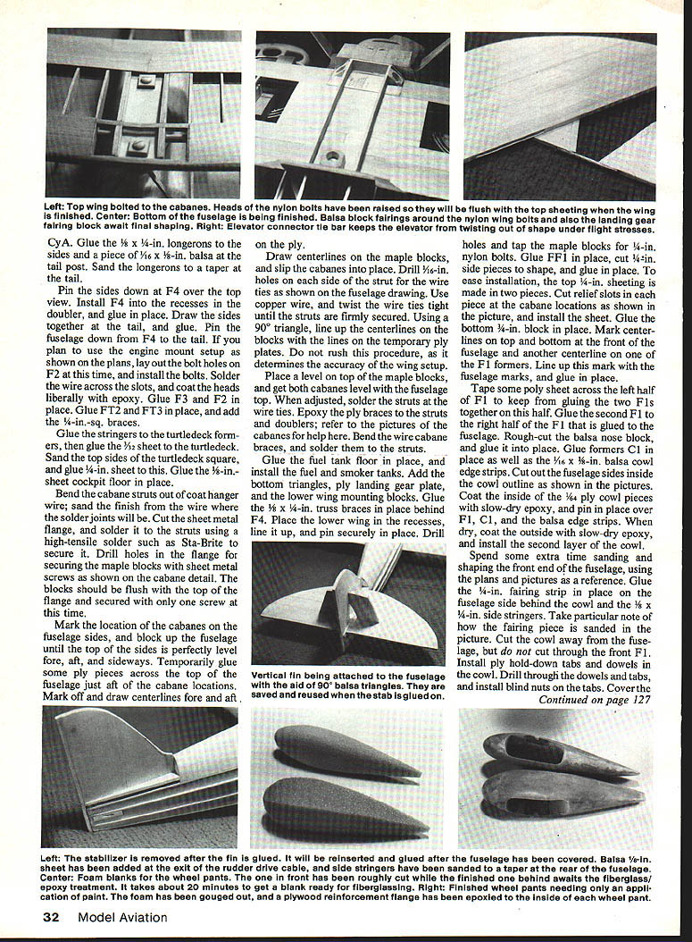
- Pin sides down at F4 over the top view. Install F4 into the recesses in the doubler and glue in place.
- Draw sides together at the tail and glue. Pin the fuselage from F4 to the tail.
- If using the engine mount setup shown on the plans, lay out bolt holes on F2 and install bolts. Solder the wire across the slots and coat heads liberally with epoxy.
- Glue F3 and F2 in place. Glue FT2 and FT3 and add 1/4-in. sq. braces.
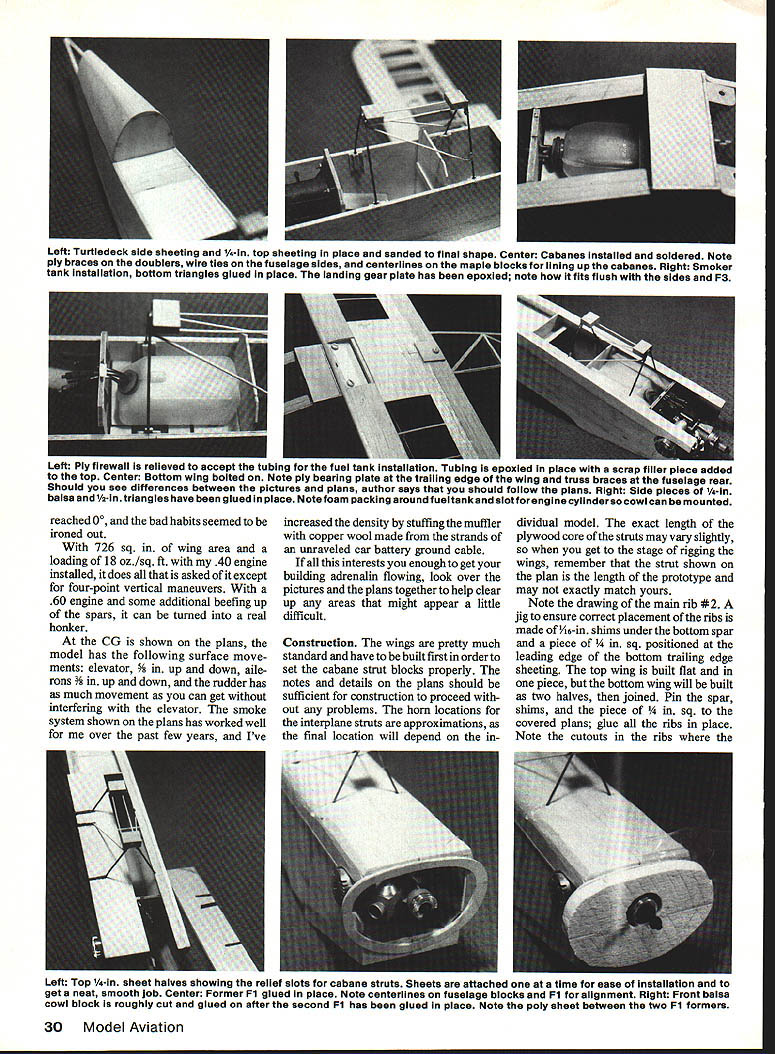
- Glue stringers to turtledeck formers and then glue 1/16-in. sheet to the turtledeck. Sand top sides of the turtledeck square, then glue the 1/8-in. sheet. Glue the 3/8-in. cockpit floor in place.
Cabane Struts and Alignment
- Bend cabane struts from coat-hanger wire. Sand the finish from wire where solder joints will be made.
- Cut sheet metal flanges and solder them to the struts using a high-tensile solder (such as Sta-Brite). Drill holes in the flange for securing the maple blocks with sheet metal screws as shown on the cabane detail. Blocks should be flush with the top of the flange and initially secured with only one screw.
- Mark cabane locations on fuselage sides and block up the fuselage until the top of the sides is perfectly level fore, aft, and sideways. Temporarily glue ply pieces across the top of the fuselage just aft of the cabane locations and draw centerlines fore and aft on the ply.
- Draw centerlines on maple blocks and slip cabanes into place. Drill 1/16-in. holes on each side of the strut for wire ties; use copper wire and twist tight to secure the struts.
- Using a 90° triangle, line up centerlines on blocks with the lines on temporary ply plates — take time here; it determines wing accuracy.
- Place a level on top of maple blocks and get both cabanes level with the fuselage top. When adjusted, solder the struts at the wire ties. Epoxy ply braces to the struts and doublers; bend and solder wire cabane braces to the struts.
Fuel/Smoker Tank and Engine Bay
- Glue the fuel tank floor in place and install fuel and smoker tanks. Add bottom triangles, ply landing-gear plate, and lower wing mounting blocks.
- Glue 1/8 x 1/4-in. truss braces behind F4. Place and pin the lower wing in its recesses, line up, and drill/tap maple blocks for 1/4-in. nylon bolts.
- Glue F1 in place, cut 1/4-in. side pieces to shape, and glue in place. To ease installation, the top 1/4-in. sheeting is made in two pieces; cut relief slots at cabane locations as shown and install.
- Glue the bottom 3/8-in. block in place. Mark centerlines on top and bottom at the front of the fuselage and on one F1 former; align and glue.
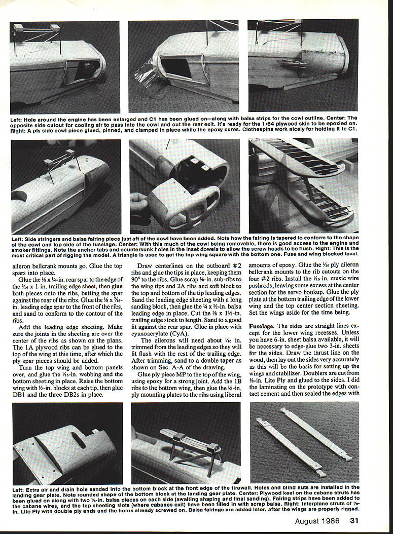
- Tape poly sheet across left half of F1 to prevent gluing the two F1s together on that half. Glue the second F1 to the right half that is glued to the fuselage. Rough-cut the balsa nose block and glue it into place. Glue former C1 in place and install 1/8 x 1/2-in. balsa cowl side strips. Cut fuselage sides in this area with a razor and fit the cowl. Glue cowl after final shaping.
- Cut the outside of the 1/4-in. top panels and install the second layer of the cowl. Spend extra time sanding and shaping the front end using plans and pictures as reference. Glue 1/4-in. fairing strip on fuselage side behind cowl and 1/8 x 1/4-in. side stringers. Make certain the cowl face is sanded to match reference photos.
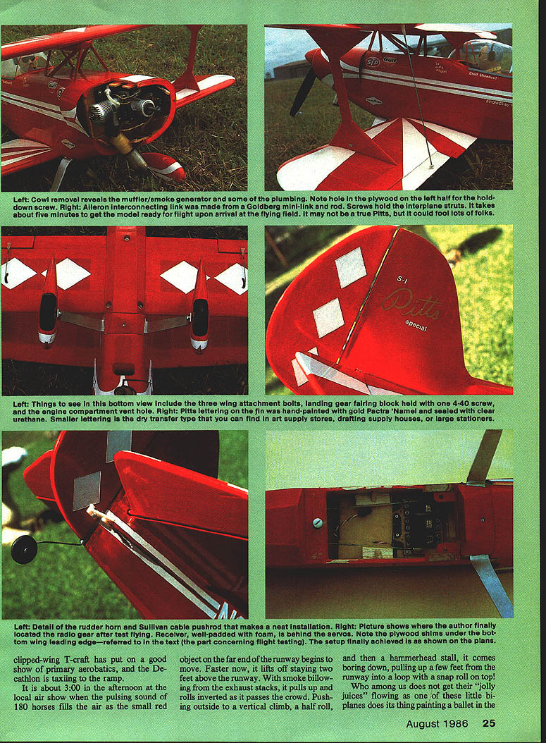
- Cut the cowl away from the fuselage but do not cut through the front F1. Install ply hold-down tabs and dowels in the cowl. Drill through dowels and tabs and install blind nuts on the tabs. Cover bolts and tank outlets with bits of fuel tubing to protect them while epoxying the inside of the engine compartment.
Joining Wings and Rigging
- Bolt the bottom wing in place and block up the fuselage until level. Set the top wing on the cabanes and, using a 90° triangle, ensure the top wing is square with the bottom wing. Drill and tap the front cabane block, screw the top wing on snugly, then recheck squareness. Drill and tap rear hole.
- Rock the top wing until the distance between #2 ribs at the interplane strut location is equal. Cut the interplane strut core to this length and add double ply pieces to the ends. Screw horns in place per picture and slot ribs to accept horn flanges. CYA glue horns to ribs, then unscrew interplane struts carefully and remove 1/4-in. mounting bolts.
- Drill pilot holes for the remaining sheet metal screws that hold maple blocks, install screws, then back off both screws on each block, smear epoxy between block and flange and screw them back down. Wipe excess epoxy off the top of the block.
- Glue the 3/8-in. cabane keel in the center of the maple blocks, then glue 1/4-in. side pieces to this and sand the cabane fairing to shape.
Landing Gear and Fairings
- Turn the model over and install landing gear and fairing block. Glue formers WF1 and WF2 to the bottom wing.
- Cut two 1/8-in. stringers and glue them to the wing. Install bolt fairing blocks (WF2) behind the wing and 1/8-in. stringers at the leading edge. Shape the landing-gear fairing block to conform to WF1 and the forward bottom block.
Tail and Controls
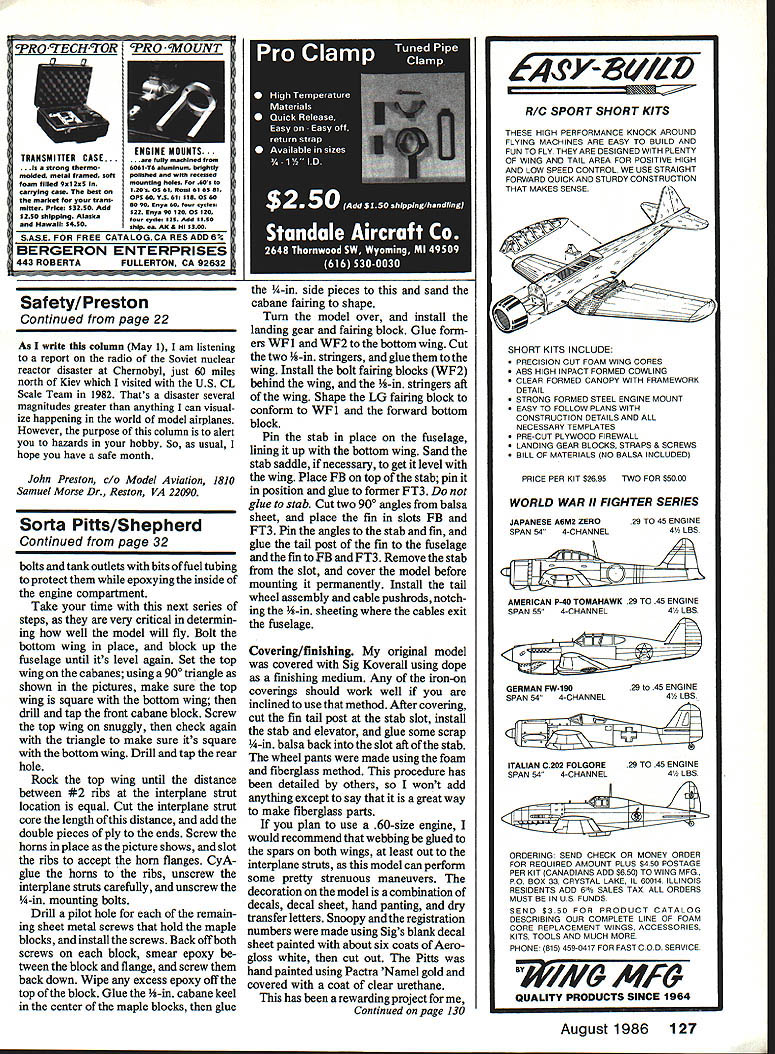
- Pin stab in place on the fuselage, lining it up with the bottom wing. Sand the stab saddle if necessary to get it level with the wing.
- Place FB on top of the stab, pin it in position and glue to former FT3 — do not glue to the stab itself.
- Cut two 90° angles from balsa sheet and place the fin in slots FB and FT3. Pin the fin, trim alignment, and glue the tail post of the fin to the fuselage and the fin to FB and FT3.
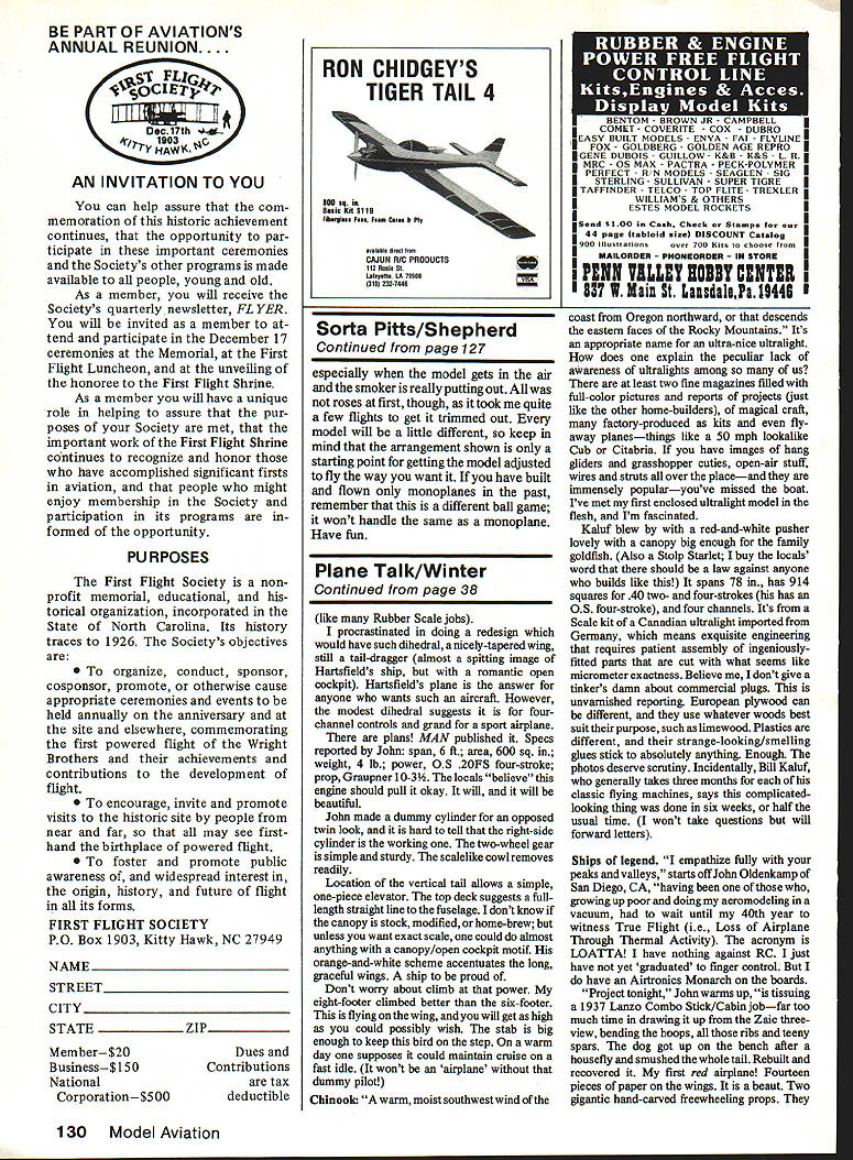
- Remove the stab from the slot and cover the model before mounting it permanently. Install the tail wheel assembly and cable pushrods, notching the 1/8-in. sheeting where the cables exit the fuselage.
Covering and Finishing
- The prototype was covered with Sig Koverall using dope as a finish; iron-on coverings will also work.
- After covering, reinstall the stab and elevator and glue scrap 1/8-in. balsa back into the slot aft of the stab.
- Wheel pants were made using foam and fiberglass — a good way to make fiberglass parts if you are familiar with the method.
- If you plan to use a .60-size engine, consider a wooden motor mount glued to the spars on both wings, at least out to the interplane struts, as the model can perform strenuous maneuvers.
- Decoration can be a combination of decals, decal sheet, hand painting, and dry transfer letters. On the prototype, "Snooky" and the registration numbers were made with Sig's blank decal sheet painted with about six coats of Aerobond white. The N number was hand-painted with Pactra 'Namel' gold and covered with clear urethane.
Flying, Trimming, and Notes
- The initial flights required trimming: CG location, aileron setup, and lower-wing incidence adjustments can all be necessary to eliminate unwanted tendencies.
- Every model will be a little different; the arrangements shown are a starting point for trimming to your flying style.
- If you have flown only monoplanes, remember a biplane handles differently — take time to trim and enjoy the learning curve.
This has been a rewarding project, especially when the model gets in the air and the smoker is really putting out. Have fun.
Transcribed from original scans by AI. Minor OCR errors may remain.

