
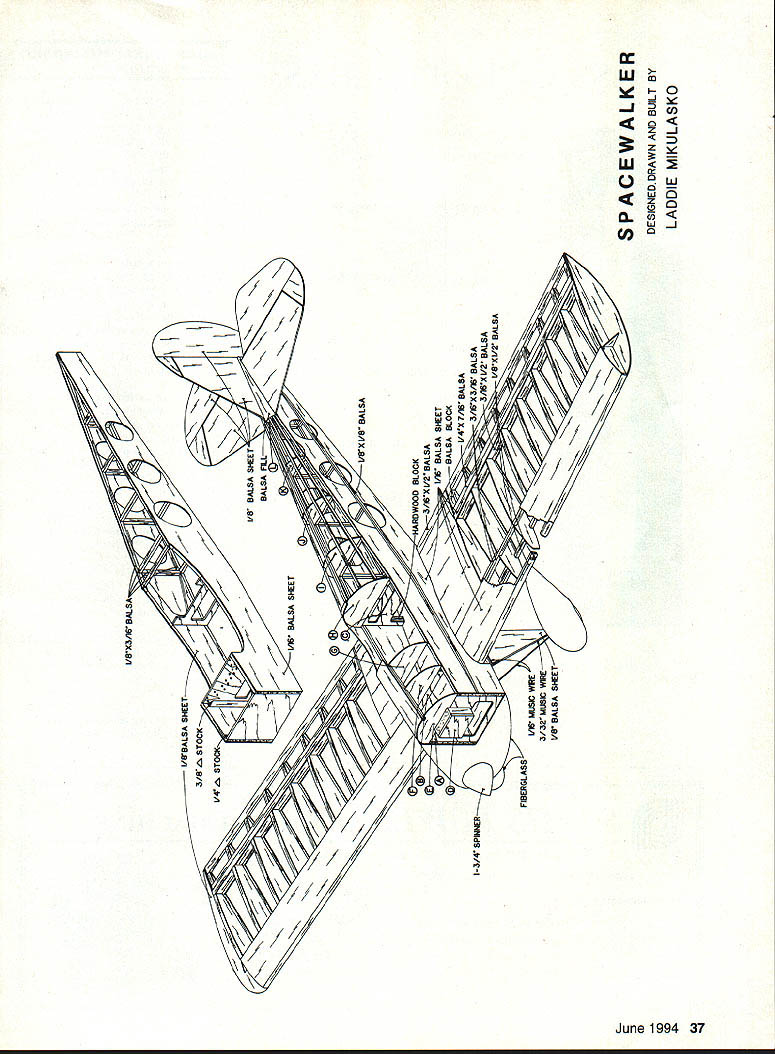
Spacewalker
Laddie Mikulasko
Since the early 1950s the Experimental Aircraft Association (EAA) has been a hotbed of home-built activity in the U.S. Many new designs have seen the light of day; each inspired someone else to come up with something better, faster, slower, safer, or just different. The movement began with more-or-less conventional designs, but by the 1980s had progressed to slick, fast composite aircraft.
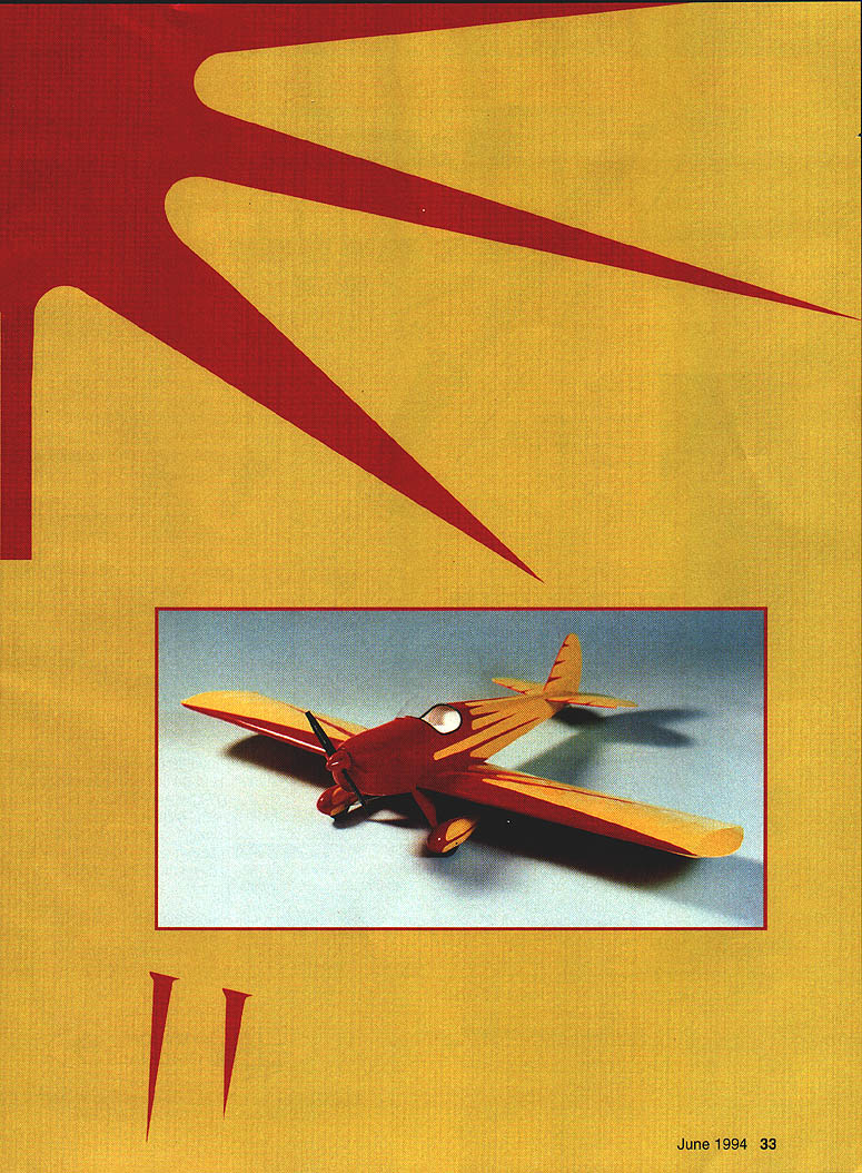
In the midst of this composite revolution, Jesse Anglin designed and built an extremely good-looking aircraft. Using wood and steel tubing as the primary building materials, Anglin created the Spacewalker, which became a popular choice in the home-building movement. In a few short years many have been built, and many more are in various stages of completion.
As soon as I saw a picture of the Spacewalker, I started to search for a good set of three-view drawings so I could create and build my own electric scale model. Shortly after obtaining the three-views, plans were drawn, and within two weeks the model was built and test-flown. The model did not disappoint: it flies as well as it looks. In the air it is stable, has good aerobatic capabilities, and is highly visible with its colorful covering. It is sized just right for the geared Astro 15 motor.
Construction
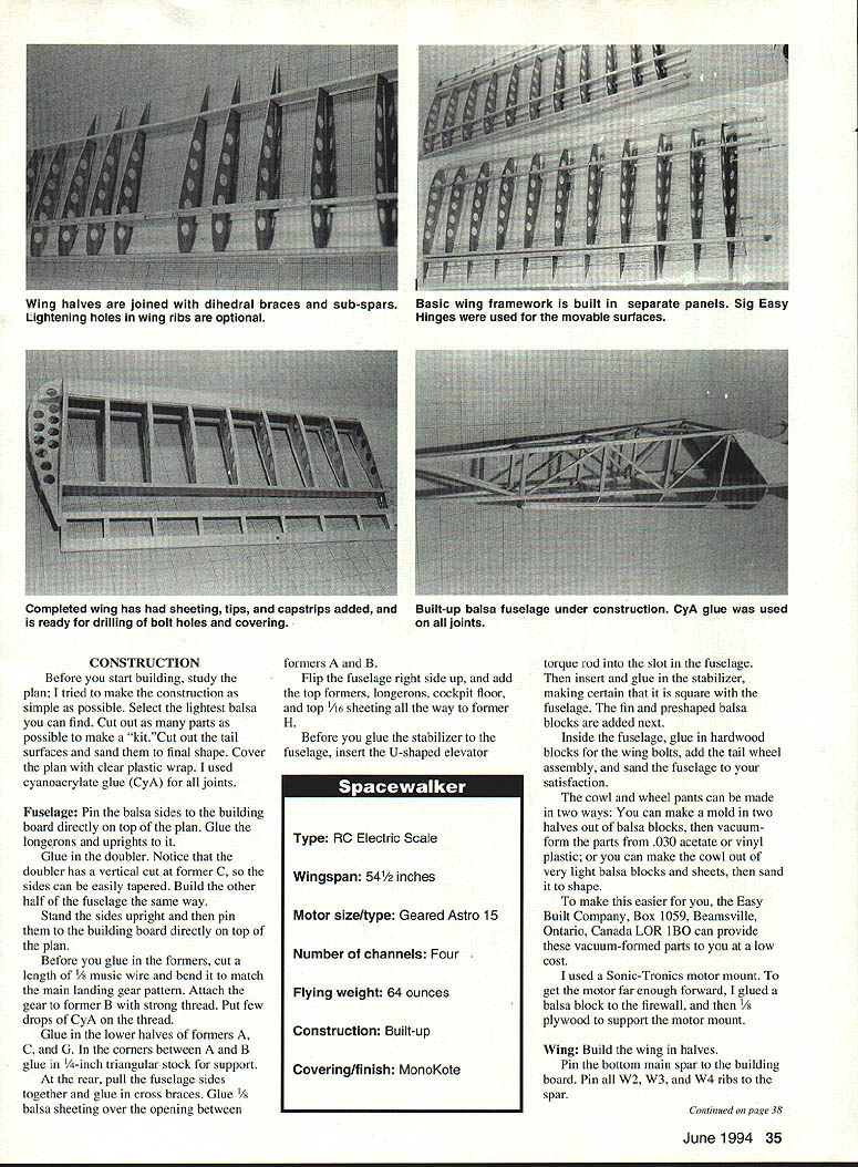
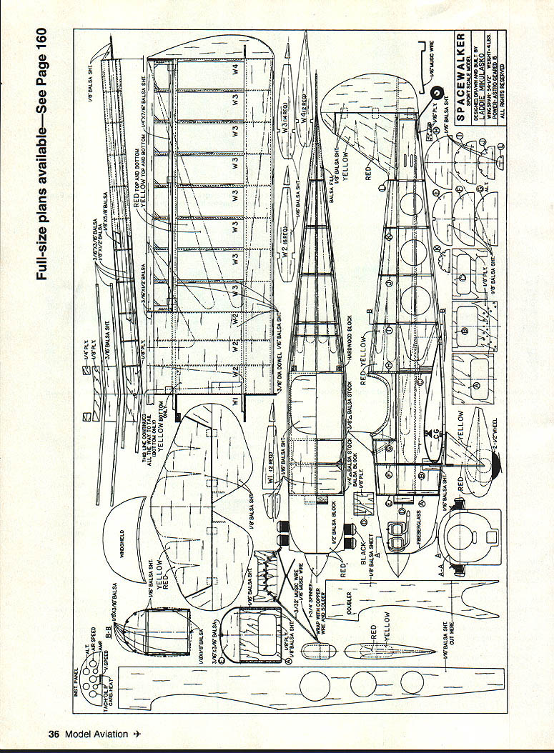
Before you start building, study the plan; construction has been kept as simple as possible. Select the lightest balsa you can find. Cut out as many parts as possible to make a "kit." Cut out the tail surfaces and sand them to final shape. Cover the plan with clear plastic wrap. I used cyanoacrylate glue (CyA) for all joints.
Fuselage
- Pin the balsa sides to the building board directly on top of the plan. Glue the longerons and uprights to the sides.
- Glue in the doubler. Note the doubler has a vertical cut at former C so the sides can be easily tapered. Build the other half of the fuselage the same way.
- Stand the sides upright and pin them to the building board on the plan.
- Before gluing in the formers, cut a length of 1/8" music wire and bend it to match the main landing gear pattern. Attach the gear to former B with strong thread and apply a few drops of CyA to the thread.
- Glue in the lower halves of formers A, C, and G. In the corners between A and B glue in 1/8" triangular stock for support.
- At the rear, pull the fuselage sides together and glue in cross braces. Glue 1/8" balsa sheeting over the opening between formers A and B.
- Flip the fuselage right side up and add the top formers, longerons, cockpit floor, and top 1/16" sheeting all the way to former H.
- Before gluing the stabilizer to the fuselage, insert the U-shaped elevator torque rod into the slot in the fuselage. Then insert and glue the stabilizer, making certain it is square with the fuselage. Add the fin and preshaped balsa blocks next.
- Inside the fuselage, glue in hardwood blocks for the wing bolts, add the tailwheel assembly, and sand the fuselage to satisfaction.
- The cowl and wheel pants can be made either by:
- making a two-half mold out of balsa blocks and vacuum-forming the parts from .030" acetate or vinyl, or
- building the cowl from very light balsa blocks and sheets, then sanding to shape.
The Easy Built Company (Box 1059, Beamsville, Ontario, Canada L0R 1B0) can provide vacuum-formed parts at low cost.
- I used a Sonic-Tronics motor mount. To get the motor far enough forward, glue a balsa block to the firewall and add 1/8" plywood to support the motor mount.
Specifications
- Type: RC Electric Scale
- Wingspan: 54-1/2"
- Motor size/type: Geared Astro 15
- Number of channels: Four
- Flying weight: 64 oz
- Construction: Built-up
- Covering/finish: MonoKote
Wing
Build the wing in halves.
- Pin the bottom main spar to the building board. Pin ribs W2, W3, and W4 to the spar. Place a 1/16" x 3/8" strip under the ribs at the rear to give rear spar support.
- Insert and pin the top spar ribs. Pin 3/16" x 1/2" rear spar ribs as well.
- Glue the ribs to the spars. Glue a 3/8" balsa leading edge strip and top 1/16" leading edge sheeting in individual sections to the W1 rib.
- Flip the half wing over and pin the spars to the building board. Again place support under the rear spar and glue the bottom 3/8" leading edge sheeting. Add capstrips and W3 ribs.
- Build the other half the same way.
- Prop up the wingtips to the correct height to obtain the proper dihedral angle. Between the top and bottom main spars glue a 1/8" plywood dihedral brace. Glue the aft brace and a second 3/16" dihedral brace.
- Glue in the top rear sub-spar; note the angle at which it is cut so the sub-spar from the other half will overlap it.
- Glue in the aileron torque rods and add the top center wing sheeting and balsa blocks that support the wing bolts.
- Flip the wing over and glue on the center-section sheeting. Attach the wingtips and build the ailerons.
- Place the wing into the fuselage saddle, check alignment, then drill holes for the wing bolts.
Lightening holes in the wing ribs are optional. Sig Easy Hinges work well on the movable surfaces.
Covering and Finishing
- The model is now ready to be covered. I used MonoKote.
- If you use the same color scheme I did, cover the whole model with yellow first. To make the trims:
- Copy the design onto a sheet of white paper.
- From a roll of MonoKote, cut two identical sheets slightly larger than the trim design. Peel the clear backing from both sheets and place them adhesive-side out so they won't stick together while you cut.
- Place the paper pattern on top and secure it to the cutting board with masking tape. With a sharp knife, cut through the paper and into the plastic. First cut the radii freehand, then use a straightedge for the straight lines. You will end up with mirror-image trims.
- To prevent bubbles under the trim sheets, puncture small pinholes in the covering only where the trims will sit. Mark the outline of the sunbursts with a soft felt-tip pen, remove the paper pattern, and make as many holes as necessary.
- Place the trims in position and iron them on with the iron set slightly lower than for full covering.
- Once covering is complete, glue on the windshield.
Assembly and Radio Installation
- Install the control horns and hinges (I used Sig Easy Hinges).
- Install the radio gear and connect the servos to the movable surfaces. Rudder and elevator pushrods are 1/8" x 1/16" hard balsa.
- Install the motor and batteries. Batteries are held to the fuselage sides with Velcro.
- Check the balance point — if not correct, reposition the batteries. Do not add ballast weight to balance an electric aircraft.
Flying
- Once all controls have been checked, taxi out and position the Spacewalker into the wind.
- The takeoff is straightforward. Do not yank it into the air; the model will pick up speed and lift off by itself.
- The model can perform most aerobatic maneuvers.
If you want more power, use a .15 to .19 glow engine — the model should fly even better, as the gas conversion would likely be lighter.
Good luck!
DESIGNED, DRAWN AND BUILT BY LADDIE MIKULASKO
Transcribed from original scans by AI. Minor OCR errors may remain.

