
Sparrow Hawk
By John O'Dwyer
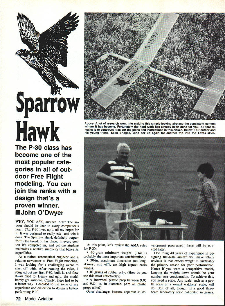
The P-30 class has become one of the most popular categories in outdoor Free Flight modeling. The Sparrow Hawk is a proven, contest-winning P-30 design that combines high performance with relative simplicity. It outperforms many rivals and has placed in every contest it's entered.
I came to P-30 as a retired aeronautical engineer and a newcomer to Free Flight modeling. After an initial heavy, poorly performing model, I used my background to design a better P-30. The following covers the design philosophy, construction details, and flying/trim tips that produced the Sparrow Hawk.
P-30 rules (AMA)
- 40-gram minimum weight (this is probably the most important consideration).
- 30 in. maximum dimension (no long, skinny, high-aspect-ratio wings).
- 10 grams of rubber only.
- A freewheel plastic prop between 9.05 and 9.84 in. in diameter.
Other practical constraints (prop type, rubber behavior, DT reliability) influence choices discussed below.
Design principles
- Minimize weight. Excess weight is the primary cause of poor performance. Use a scale (postal or three-beam laboratory scale calibrated in grams) to pick the lightest materials and to ensure you fly at the maximum legal weight (1 oz = 28.34 g).
- Span, aspect ratio, and wing loading. With a 30 in. wingspan limit, choose a low aspect ratio and low wing loading. An aspect ratio between about 6:1 and 7:1 is a practical lower limit to avoid excessive induced drag and structural problems.
- Airfoil selection. Small, slow models require airfoils optimized for low speeds (typical P-30 flight speeds 8–10 ft/s). Studies (e.g., Althaus, Stuttgart low-speed tunnel) and practical tests indicate certain cambered undercamber airfoils with a turbulator can give a substantially higher lift/drag ratio. The Clark Y-style flat-bottom can be used, but a properly chosen low-speed airfoil is preferable.
A good part of success comes from careful material selection, precise construction, and minimizing both structural and finishing weight.
Fuselage
Materials and selection
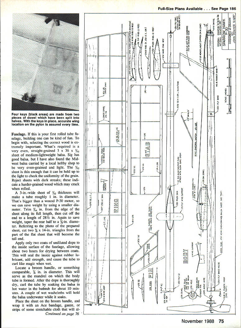
- Use a very even, straight-grained 3 x 36 x 1/2 in. sheet of medium-lightweight balsa for a rolled-tube fuselage. Reject sheets with dark streaks (harder grain that may crack when rolled).
- A 3 in.-wide sheet of 1/32 in. thickness makes a tube roughly 1 in. diameter—larger than needed for a P-30 motor. Trim 7/16 in. off one long edge to reduce diameter, then cut the length to 28-1/2 in.
- Taper the rear half to 3/8 in. diameter. From the tail end of the flat sheet, cut two 3/8 x 14 in. triangles for tail shaping.
Tube forming
- Apply two coats of undiluted dope to the inside surface, drying about two hours between coats. This seals against rubber lubricant, adds strength, and helps curling.
- Soak the sheet in hot water about 10 minutes. Use a 7/16 in. diameter mandrel (broom handle or dowel).
- Wrap the wet sheet on the mandrel with an Ace bandage, gauze, or stretchable cloth and let dry about 24 hours. The mandrel should be sized so the straight edges do not quite touch.
- After drying, slide the tube off the mandrel. Squeeze the straight section together and secure with cyanoacrylate (CyA). Then close the aft taper. Use CyA sparingly to save weight.
Nose and tail reinforcement
- Add 1/2-in.-wide strips of 1/4-in. plywood (about 3 in. long) as bands inside and outside the nose; soak and form them on the mandrel, hold with rubber bands until dry, then glue with CyA. The outside band supports the rear rubber post.
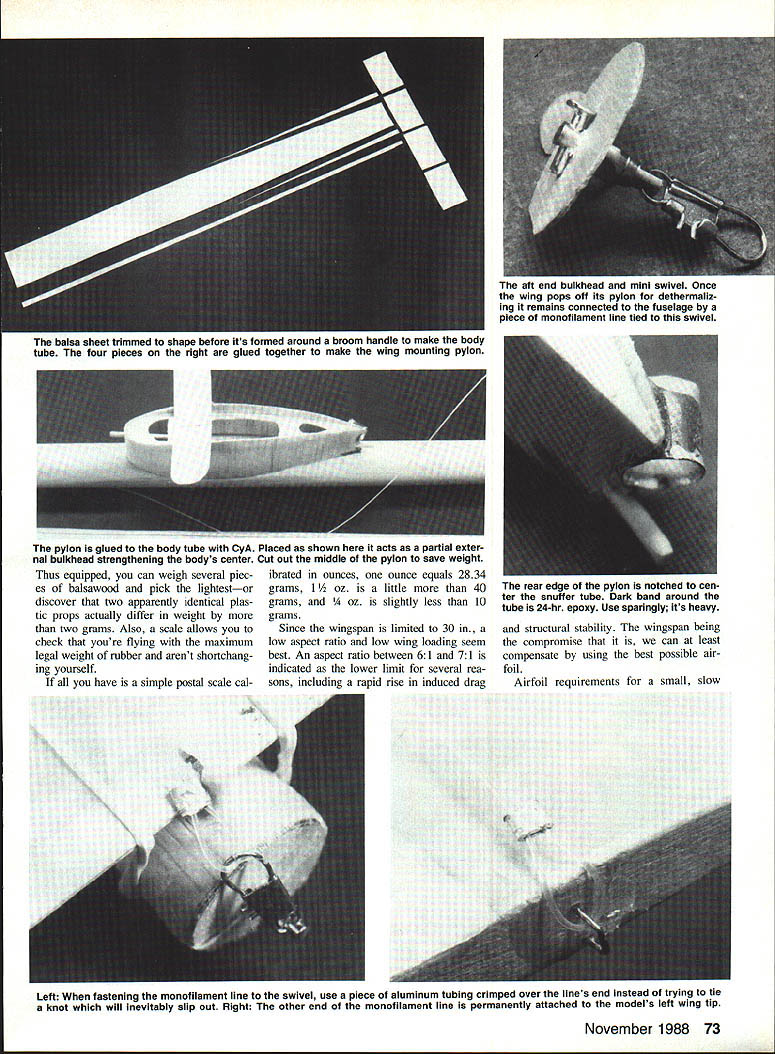
- Cut a 1/8-in. plywood disc to match the aft tube diameter, drill a 1/16-in. hole in the center, and install a small fishing swivel through it (secure with a pin and 5-minute epoxy). Glue and reinforce with silk or nylon strips.
- Wrap a single 1/2-in.-wide silk strip with 5-minute epoxy around the front end for reinforcement. After epoxy sets, cut three 3/8-in. notches into the forward edge: the upper one positions the nose plug; the two side notches keep the winding safety pin from turning during motor winding and prop installation.
Wing‑mount pylon
Making the pylon
- Cut a 7-1/2 in. piece off the sheet, then cross-grain it into four equal pieces. Glue edge-to-edge with CyA to make a 1-5/8 x 12 in. strip for forming the pylon.
- Use two symmetrical airfoil ribs from the plans as templates (make Xerox copies, transfer by ironing the copy face-down onto balsa, or trace).
- Glue the two ribs together with small spar-like rectangles, center on the 12-in. strip, and glue at the nose. Gradually wrap each side around to the trailing edge with CyA, trim excess, and rough-shape for sanding.
- Sand the pylon using 180-grit paper wrapped around the mandrel or fuselage. Cut out some rib material to save weight.
Mounting and fittings
- Notch the rear edge of the pylon to center the snuffer tube. Attach the aluminum snuffer tube at the shown angle with slow-dry metal-bond epoxy—use a thin band only, as the epoxy is heavy.
- Glue the pylon to the body tube 6-1/2 to 7 in. from the nose. Align the tube seam on the bottom centerline before attaching.
- The pylon acts as a partial external bulkhead. Cut out the middle to save weight where appropriate.
Snuffer and swivel details
- The rear snuffer tube is centered in the pylon; a dark band around the tube indicates a bead of epoxy—use sparingly.
- The aft fishing-swivel mounting and reinforcement are important for the dethermalizer system (see Assembly section).
Fin and tail
Making the fin
- Make Xerox copies of the fin and tail ribs to use as patterns.
- Build the fin on the plan (the fin is cambered for a left turn: cambered on the right, flat on the left). Use a spray-adhesive-covered workboard, cover with wax paper, and build directly on that surface.
- Sand lightly and paint outer edges with one coat of balsa sanding sealer.
Covering and alignment
- Cut Japanese tissue with the grain running in the longest dimension. Coat the structure with thin dope and lay on the tissue, stretching out wrinkles. For problem areas, dampen with a little thinner.
- The fin trailing edge is long enough to extend through the body tube for added attachment strength. Line the fin up on the vertical with the wing pylon; the flat side should be parallel to the body centerline.
- Water-shrink the fin tissue, then brush on one coat of very thin nitrate dope. Finish with two coats of thin sanding sealer to waterproof the outside of the body tube and pylon, sanding lightly between coats.
Stabilizer
- Construct the stabilizer using the lightest wood possible and as few coats of dope as practical (one coat is often sufficient in dry climates).
- There is a small notch in the trailing edge center. This mates with a short 1/16-in. dowel peg inserted at the rear of the fuselage to keep the stab aligned. The peg also keeps the stab hold-down rubber off the dethermalizer (DT) swivel.
- Glue the stabilizer rest with the left side about 1° high to aid the left-turn glide.
Wing
Ribs and airfoil
- Make a plywood or aluminum template from the main wing rib Xerox. Stack and cut all balsa ribs using the template. Place two pieces of 1/16‑sq. balsa in the center of the rib stack as spacers.
- Taper and sand the trailing edges to provide washout. Glue ribs to the spar and leading edge.
Sheeting and dihedral
- Install center sheeting and 1/32-in. top sheeting. Build dihedral and tip panels separately, join, and add tip dihedral braces.
- This design uses a fairly steep "V" dihedral (saves about 1.5 g over polyhedral). Use a triangular dihedral checker to set center ribs at the proper angle before gluing.
Undercamber and turbulator
- Pin down the trailing edge on the wax-paper-covered plan, blocking up the forward edge about 1/32 in. The 1/16-sq. rib jig strip should be about 3/8 in. forward of the trailing edge to assure an accurate undercamber—important for low-speed airfoil performance.
- Cover with Japanese tissue with the grain spanwise.
- The turbulator can be made from HO-gauge 2x4s (model railroad ties) and placed as shown on the plans; it improved glide performance in testing.
Finishing
- Dope and tissue the wing as with the tail. Cut wing tips from 1/32-in. sheet and sand to shape.
- Make sure the wing is mounted so the root incidence matches climb and glide settings shown on the plans.
- Finish the wing so it is free of warps, wash-in, and washout; a generous dihedral and correct pylon height reduce the need for intentional warps.
Propeller assembly
Propeller types
- Common suitable props: Japanese rounded-tip types (green, blue, or silver-gray), about 9-1/2 in. diameter, 7-1/2 in. pitch, and 6.8–7.1 g. A European-import square-tip prop is about 9-1/2 in. diameter with a nominal 9-in. pitch and weighs about 7 g (often available in yellow).
- By AMA rules, it is illegal to sand or shave a P-30 prop to balance or lighten it.
Performance testing
- Comparative glide tests from indoor bleachers showed the square-tip prop gave approximately 15% longer endurance than rounded-tip props, probably due to higher pitch and lower blade area. The higher pitch also helps by reducing initial acceleration and slightly lengthening the prop run.
Assembly tips
- Assemble the prop and nose block in the standard way. Bend the short outer end of the shaft first to about 95° with as small a bend radius as possible; the freewheel notch will work better and last longer. Bend the hooked part last.
Assembly and dethermalizer (DT) system
Why a different DT
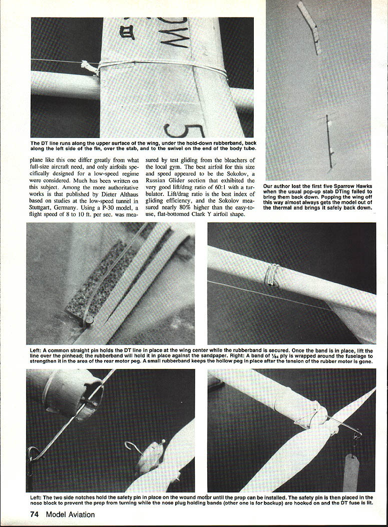
- The first five Sparrow Hawks were lost to thermals even with a conventional pop-up-tail DT. The very light wing loading of P-30s requires a more reliable system.
Monofilament line DT system
- The system used (variation attributed locally to Ken Wernicke / George Xenakis): a lightweight DT fuse (Peck's 3/16-in. diameter fuse is recommended) burns through the #32 rubberband wing hold-down. The wing pops off but is retained by 12-lb.-test monofilament fishing line attached from the wing tip to the tail swivel. The freewheel prop and spinning wing restrain the model during the descent.
- This system reliably breaks the model out of thermals and allows gentle landings; models have survived concrete runways without prop or nose breakage.
- A drawback: fishing line can wrap in trees; solution is to cut the line and replace as needed.
Attachment details
- Do not try to tie the monofilament. Use a short piece of 1/16-in. aluminum tubing squeezed with pliers to secure the line—easier to adjust and more reliable.
- A short piece of the head end of a straight pin protrudes from the top of the wing centerline. To assemble: pull the fishing line taut from the tail, over the stab, around the pin, and out to the wing tip. Monofilament has enough stretch to stay taut if cut to proper length.
- Put the wing hold-down rubber band over the line to hold it in place during flight.
- Glue four keys made from split halves of a 1/8-in. dowel onto the wing to help align it accurately when reattaching.
Wing hold-down and safety
- Put two small rubber bands on the front end of the body tube behind the little triangles. One serves as a backup since replacement is difficult when the motor is wound.
- Cut a short piece of DT fuse and slide it into the snuffer tube. Use tweezers to hold the wing mount rubber band back during insertion and ensure it is positioned against the fuse (not the snuffer tube).
Rubber motor and installation
Rubber specifics
- The Sparrow Hawk flies best on four strands of 3/64-in. rubber. Ten grams of FAI or Champion rubber will be about 78–80 in. long.
- Wash off the powdered preservative in soapy water before assembling.
Knotting method
- Tie a single overhand knot as close to each end as possible.
- Lay the two ends adjacent and tie another overhand knot of the two strands.
- Lubricate liberally (saliva recommended in the instructions) and pull the knot very tight; the small knots act as limit stops.
- Cut off excess.
Installation and lubrication
- Coat the rubber with a good-quality rubber lube and install it in the body tube using a push stick of adequate length.
- The rear rubber support tube is retained with a small rubber band as shown in the plans.
Trim, balance, and preflight checks
Center of gravity
- With the prop installed, check the center of gravity. It should balance on the rear spar of the bottom surface of the wing. If more than 1/4 in. off, add a little lead tape at the light end. To avoid last-minute balancing, consider waiting to glue the pylon until this step.
Warp control
- Check the wing and tail for warps and steam-out as necessary.
Identification
- For contest use, put your AMA number on the right wing and your name/address somewhere on the plane (address stickers work well).
Flying and trimming
Preflight
- Wait for a calm day to test fly. Lubricate the prop and shaft before each session with thin oil (sewing machine oil in a pencil dispenser is convenient).
- Test glide and shim or trim the rear stab support until you obtain the slowest possible glide without stalling.
First flights and adjustments
- Wind about 200 turns for an initial test flight (use a winder and the flagged safety pin notches).
- Light the DT fuse with another piece of fuse—never use a match or cigarette lighter on the airplane itself (nitrate dope on tissue is very flammable).
- Launch slightly nose-up and a little left of the wind.
Expected performance
- On correct thrust-line settings, the model should gently climb in a right spiral for ~10 seconds, then glide in a large left circle. A short DT fuse can cause premature disassembly in strong climb—be cautious.
Trim tips
- If it does not climb on 200 turns but flies much faster than glide speed, reduce downthrust.
- If flight speed is slow and there's no climb, try stronger rubber.
- If speed is up and the right turn is tight with very little climb, reduce right thrust and retest at 200 turns.
- Do not change thrust line if the plane flew well at 200 turns—adjust CG and elevator first.
Power curve and trimming persistence
- Gradually increase turns to 650–700 as trimming progresses. Around ~500 turns you will encounter the "knee-in-the-torque" region where available power rises rapidly. Persist with trimming through this zone—many give up here but contests are won by those who keep adjusting.
Prop gyro effect
- The freewheel prop out on the nose acts as a gyro and stabilizer. The slower the glide, the less effect the prop has on the glide path.
Practice
- There is no substitute for practice and experimentation. P-30 is a forgiving, inexpensive trainer for learning trim techniques.
Good luck—bring a Sparrow Hawk to the next contest and we'll both have winners.
Transcribed from original scans by AI. Minor OCR errors may remain.

