
Spectra
By Bob Kopski
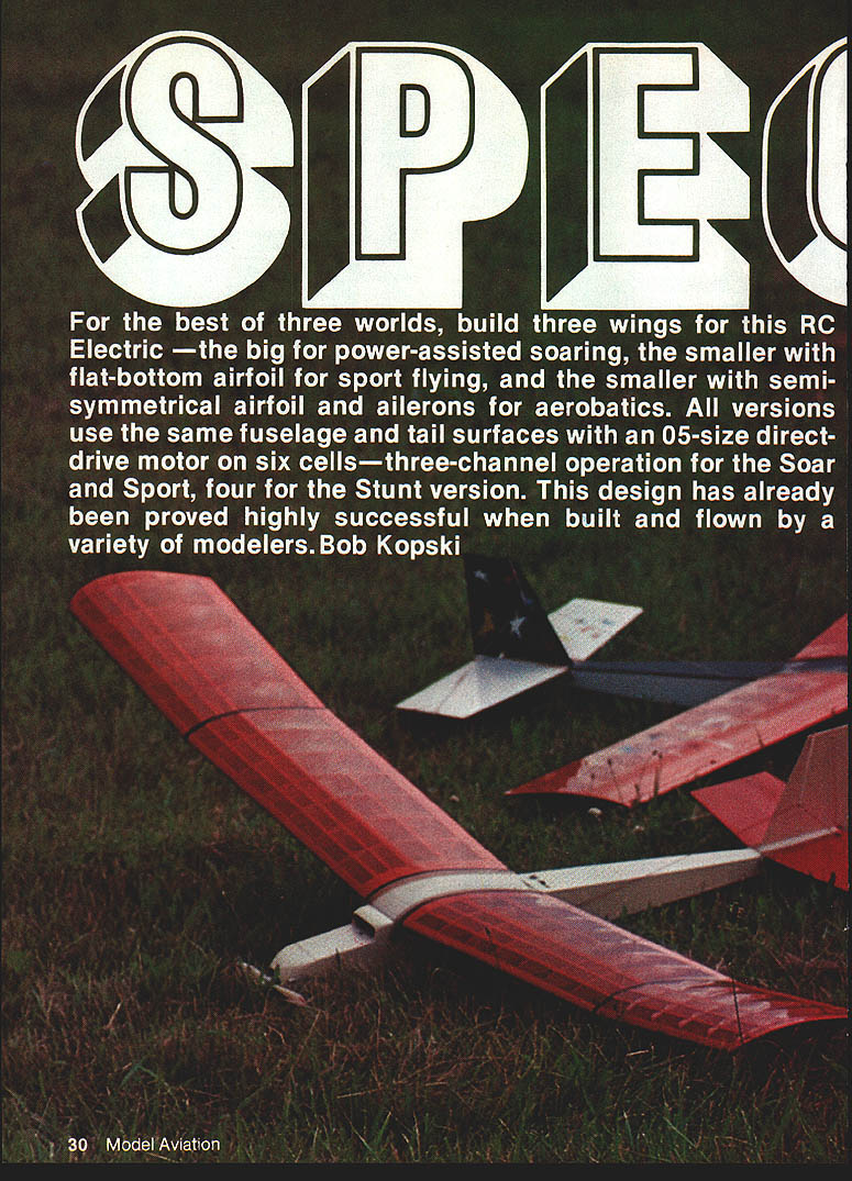
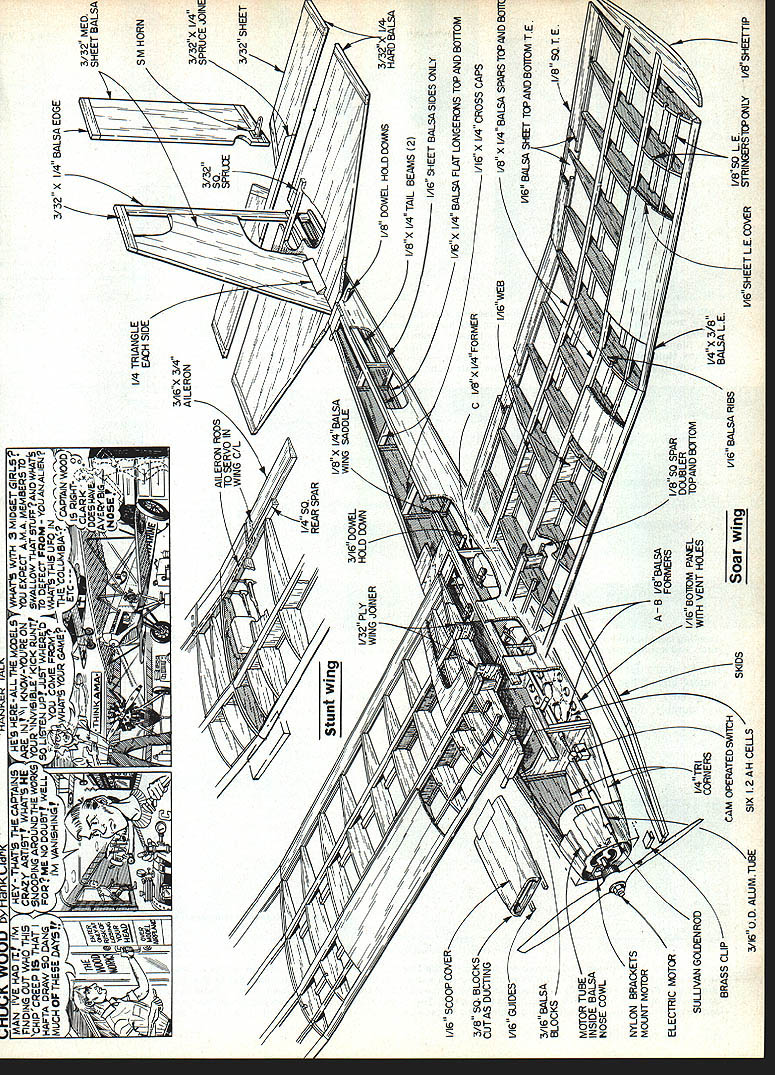
For the best of three worlds, build three wings for this RC electric: the big wing for power-assisted soaring, the Sport wing with a flat-bottom airfoil for general flying and windy days, and the Stunt wing with a semi-symmetrical airfoil and ailerons for mild aerobatics. All versions use the same fuselage and tail surfaces with an .05-size direct-drive motor on six cells — three-channel operation for the Soar and Sport, four for the Stunt version. This design has been proved highly successful when built and flown by a variety of modelers.
If you are new to electrics, consult the MA series on Electrics beginning September 1983 and the RC Electrics column that started in July (references in original MA issues). This article assumes you are a reasonably skilled builder; it discusses the design, construction techniques, and installation details rather than step-by-step assembly instructions.
Variants
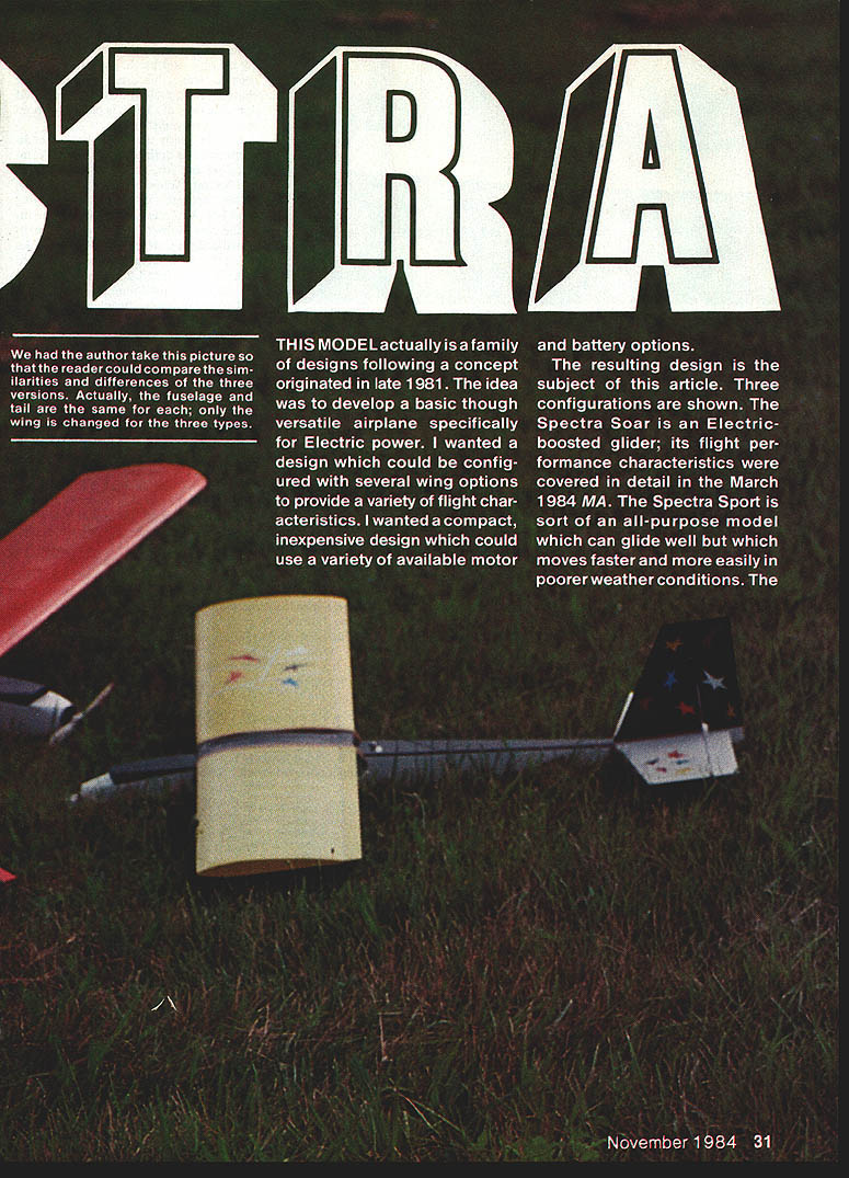
- Spectra Soar — Electric-boosted glider version; long-proven 12½% flat-bottom airfoil with turbulators, best for thermalling and long glide times.
- Spectra Sport — All-purpose wing: moderate span, flat-bottom 10% section, no ailerons, higher wing loading for better penetration in wind; a good trainer.
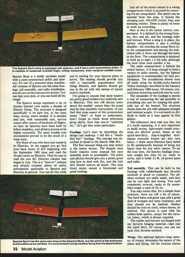
- Spectra Stunt — Same span as Sport but with a semi-symmetrical airfoil and ailerons for sustained inverted flight, rolls, and mild aerobatics; still fairly docile.
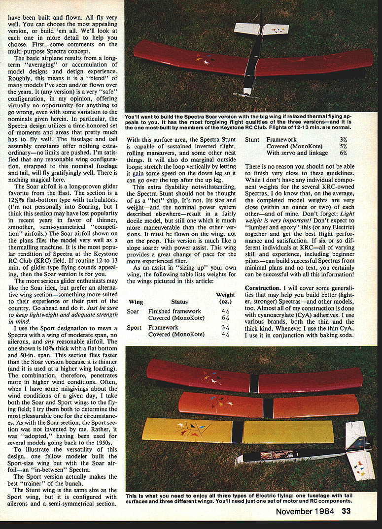
You can pick which wing to build or build all three and swap them on the same fuselage, tail assembly, and radio installation.
Fuselage
Concept and layout
The fuselage is a modified box-fuselage designed specifically for electric power: light, strong, and durable. The distinctive motor-mount is a shapely nose block that is functional and attractive. Just aft of the motor mount is an air-scoop hatch that gives access to a wiring compartment containing the charging jack, ON-OFF switch, fuse or damping resistor, and room for wiring and adjustments.
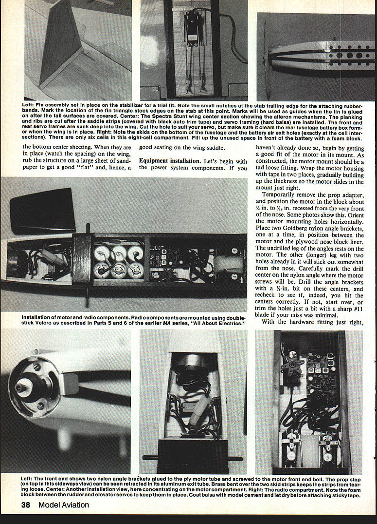
The motor/battery compartment is defined by strong fore and aft formers, the fuselage sides and bottom, and the wing when installed. The compartment doubles as a cooling chamber: air enters the scoop, flows among the individual cells, and exits through holes in the floor. The compartment is designed to hold up to eight 1.2‑Ah cells, although six is the more common installation.
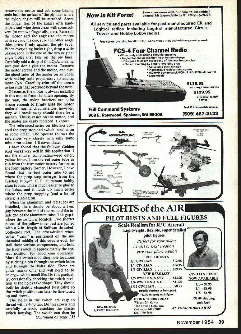
The radio compartment behind the battery is large enough for a variety of radio systems; light equipment is recommended. Installations can use double-sticky-backed Velcro (as described in the original MA series) or conventional mounting methods.
The remainder of the fuselage simply connects the tail assembly and keeps pushrods out of the airstream. Built carefully, the structure provides adequate strength at minimal weight: the fuselage structure weighs less than 2½ oz ready to cover and will hold roughly 1½ lb of power parts and radio gear.
Wiring and cooling
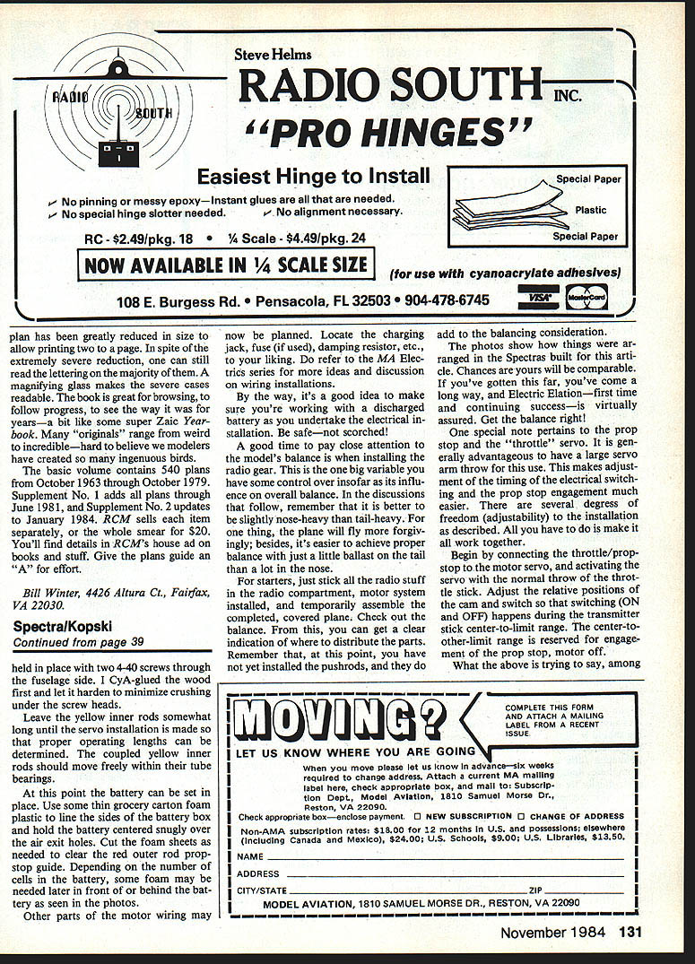
Keep wiring neat and secure. Plan servo and lead placement so pushrods are straight and free from binding. Use foam blocks or wood spacers glued in place for servo location before applying Velcro or tape. Make sure battery placement allows airflow around cells and clear air-exit holes.
Electric power
Many quick-and-dirty construction techniques are heavy; weight is critical for electric flight. Spectra’s structure is deliberately light so it flies well with reasonable power and battery weight. The design is intended to survive seasons of use with proper care.
Tail assembly
The tail assembly can be rubber-banded to the fuselage (author’s preference) or glued. All-sheet tail surfaces can be very light and strong; two covered, ready-to-fly tail surfaces weigh about 2½ oz total. Use hard balsa end-grain caps for strength and warp resistance and iron-on cloth where shown. Spruce reinforcements are used in the rubber-held option except for the elevator joiner, which is always required. Rudder and elevator hinges: tape hinging works well (see original MA reference), although other methods are acceptable.
Wings
General concept
The optional wing choices determine flight characteristics. The Spectra design is the result of long experience and uses conservative moments and areas that reliably fly well. Any reasonable wing configuration attached to this fuselage and tail should fly gratifyingly well as long as weight and strength are respected.
Airfoils and roles
- Soar — 12½% flat-bottom airfoil with turbulators; excellent thermalling and glider-type performance. Popular at the Keystone R/C Club; typical flights of 12–13 minutes are achievable.
- Sport — 10% flat-bottom airfoil, 50 in. span, no ailerons; higher wing loading and better penetration in wind. Good trainer and general-purpose wing.
- Stunt — Same span as Sport with a semi-symmetrical airfoil and ailerons; capable of sustained inverted flight, rolls, and marginal outside loops. More maneuverable but not a “hot” ship — should be flown on the wing, not on the prop.
A fellow modeler once built the Sport-size wing with the Soar airfoil for an “in-between” configuration.
Wing weights (guidelines)
- Soar — Finished framework: 4½ oz; Covered (MonoKote): 6½ oz.
- Sport — Framework: 3¾ oz; Covered (MonoKote): 4½ oz.
- Spectra Stunt — Framework: 3¾ oz; Covered (MonoKote): 5½ oz; With servo and linkage: 6¾ oz.
Aim to finish close to these guidelines. Light weight is essential — avoid heavy gluing and overdressing.
Construction
Adhesives and joints
Most assembly uses cyanoacrylate (CyA) adhesives:
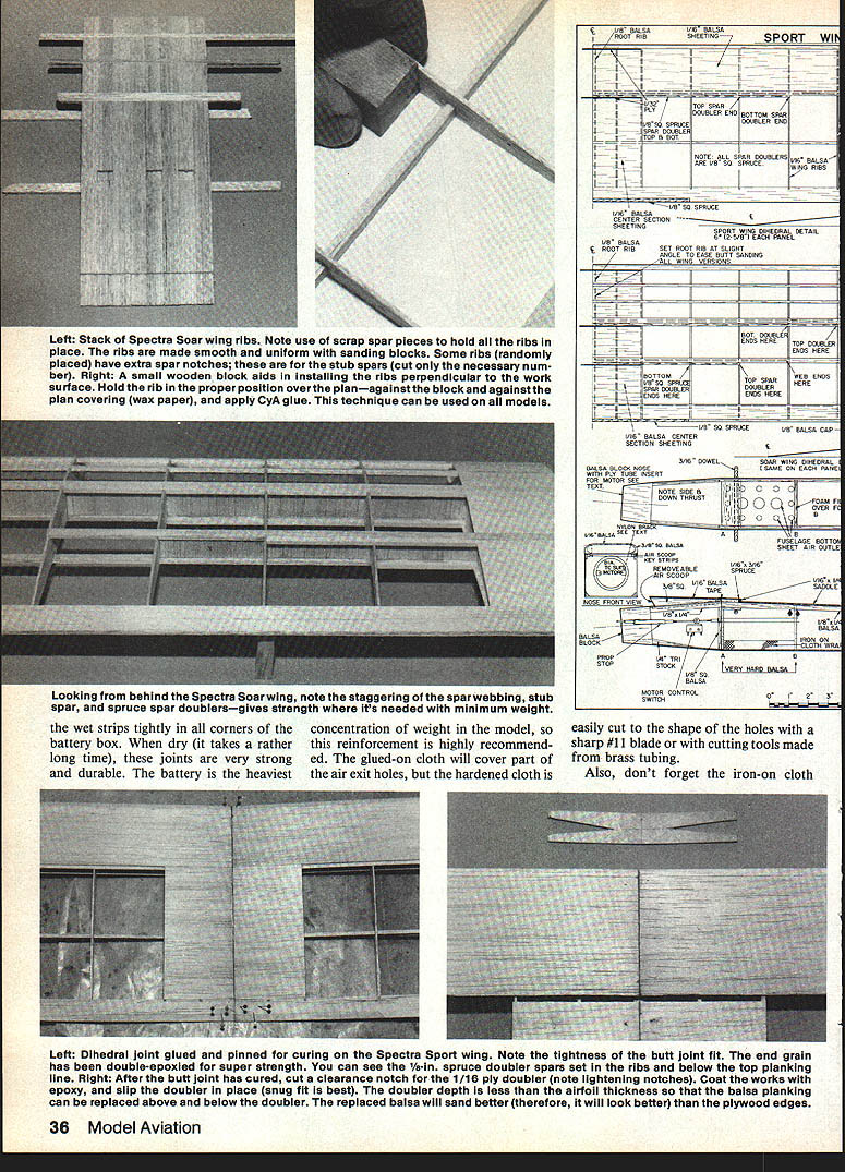
- Thin CyA with baking soda as an accelerator creates instant, rock-hard joints (useful for rib-to-LE/TE, center sheeting, formers, uprights, cap strips, etc.). Joint fit must be good.
- Thick CyA is used where extra working time is needed (edge-gluing stabilizer sheets, end-grain caps, spar webs, top spars, wing planking). Do not use baking soda with thick CyA.
- Epoxy is used only at the dihedral joints (slow-curing epoxy soak-and-fit technique gives super-strong joints) and in the nose block assembly where larger area bonding is required. The nose block itself is attached to the fuselage with CyA.
Always select wood by intended use: harder balsa floor under motor battery, lighter sheeting elsewhere; harder wood nearer wing center, lighter toward tips; LE and nose block wood should be light and carveable.
Battery-box reinforcement
Reinforce inside of the battery box with lightweight cloth strips about 1 in. wide coated with white or yellow glue and “plastered” around the inside. This adds shelf strength without much weight. The cloth will cover part of the air-exit holes; cut it out cleanly with a sharp blade if needed. The battery is then secured with a strap or Velcro.
Spar doublers and Stunt wing specifics
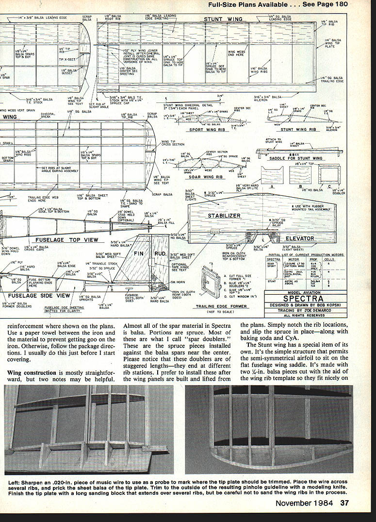
Most spar material is balsa with spruce “doublers” near the center. These doublers are staggered to end at different rib stations; install them after building the wing panels by notching ribs and slipping doublers in place with baking soda and CyA.
The Stunt wing has a simple structure to permit the semi-symmetrical airfoil to sit on the flat fuselage wing saddle; made from two 1/4 in. balsa pieces fitted with the rib template.
Equipment installation
Motor mount and fitting
- Wrap the motor housing with tape in two places to achieve a snug sliding fit in the mount.
- Temporarily remove the prop adapter and position the motor recessed about 1/4–3/8 in. from the nose front. Orient the motor mounting holes horizontally.
- Use two nylon angle brackets (Goldberg style) between motor and plywood nose-block liner. Mark and drill bracket holes carefully, bolt brackets to the motor, and trial-fit the assembly in the nose block.
- Remove motor, apply a generous fillet of epoxy to the plywood where the brackets seat, reinstall motor and brackets, tighten screws, and add small epoxy fillets outside the brackets after curing for added strength.
- To permanently secure angle brackets to the ply liner, score bracket legs, clean them, and use a drop of thin CyA with baking soda on mating surfaces — avoid gluing the motor to the mount. Trim excess nylon beyond the nose when done. The nylon brackets are strong but designed to shear away in severe mishaps to protect the motor.
Prop stop and switch
- The Sullivan Golden Rod prop-stop tubing works well: use the smaller combination (red outer, yellow inner). Use 3/16-in. O.D. aluminum tubing at the fuselage exit for strength where prop-stop stress occurs.
- Leave about a 3-in. gap between the red outer tube end and the inside of the aluminum tube; the switch is located in this gap.
- Join two short sections of yellow inner rod with a 2-in. length of Sullivan threaded rod. Place a cross-drilled wheel-collar cam on the unthreaded center. Adjust the lever switch position using pins through fuselage sides as guides and file holes gradually. Thread switch holes with a 4-40 tap slowly and carefully to avoid cracking the plastic; secure with 4-40 screws. CyA the wood first under screw heads to avoid crushing.
- Leave yellow inner rods long until servo installation is finalized so operating lengths can be set. The rod assembly should move freely.
Wiring and components
- Locate charging jack, fuse/damping resistor, and ON-OFF switch in the wiring compartment to suit your layout; refer to the MA Electrics series for additional wiring ideas.
- Make sure you work with a discharged battery during electrical installation for safety.
- Keep all wiring neat and secure.
Motor/servo and prop-stop coordination
- Use a large servo-arm throw for the throttle/prop-stop servo to ease adjustment of timing between electrical switching and prop-stop engagement.
- Adjust cam and switch so the motor is ON when the prop stop is retracted and OFF when the prop stop is engaged. There should be a comfortable range where the motor runs but the prop stop is not engaged. The motor must not be running when the prop stop engages.
Skid and coverings
- Many builders use the Ace R/C glider skid cut into two 1/4-in.-wide pieces arranged around the air-exit holes; anchor the skid securely at the nose with 1/8-in.-wide brass to prevent tearing off.
- If the field ground is harsh and bottom covering tears, scuff on auto trim tape stripes along the fuselage bottom for protection and appearance.
- When using iron-on cloth, follow package directions and use a paper towel between iron and cloth to avoid residue on the iron.
Balance, weights, and flying notes
- For initial balance checks, install radio gear and motor system, temporarily assemble the covered plane and check CG. Pushrods add weight and should be considered.
- It is better to be slightly nose-heavy than tail-heavy. A little tail ballast is easier than much nose ballast.
- Finished weight target with six 1.2‑Ah cells: about 35–39 oz. Over 40 oz will hurt flying ability; under 35 oz is exceptional.
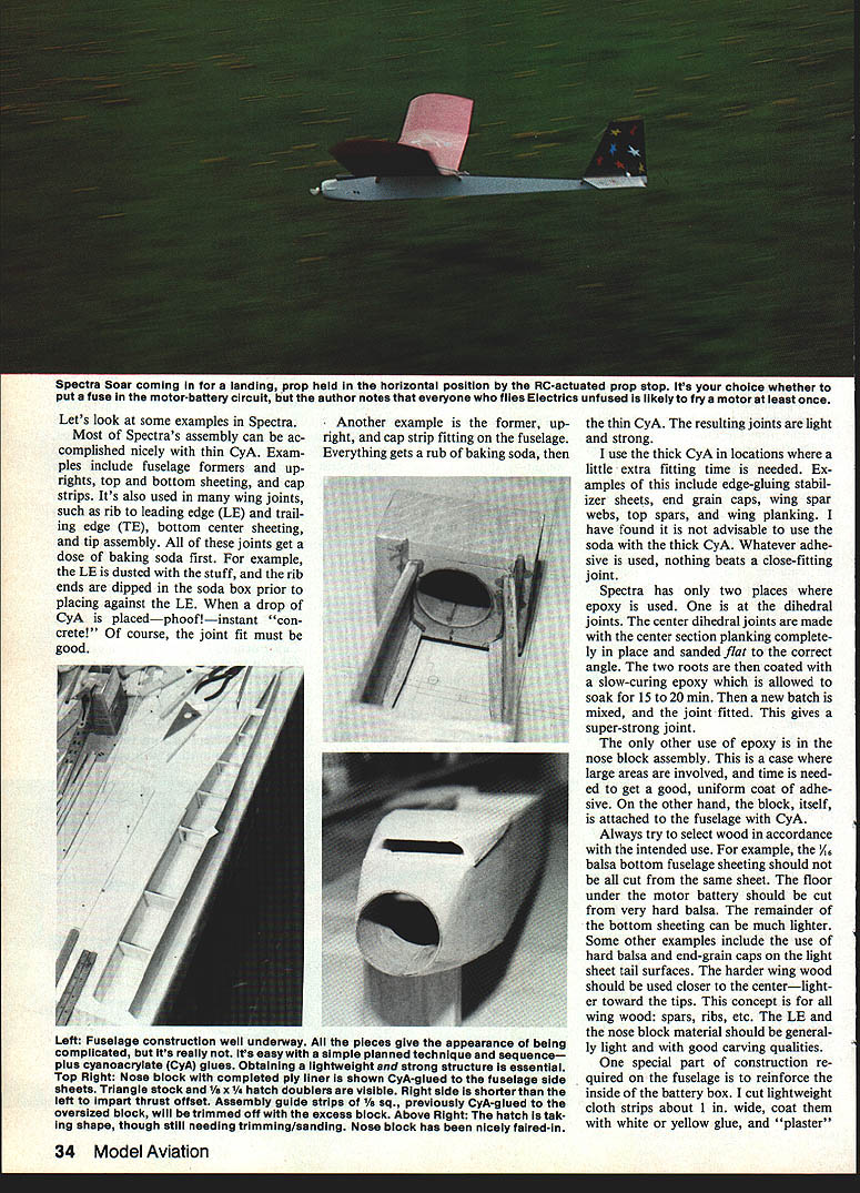
- Electrics fly on the wing, not on the prop — go easy on up-elevator and fly smoothly.
Final remarks
The Spectra design reflects years of experience and has been built successfully by several modelers. Keep weight down, build true and warp-free wings, and use the variant best suited to your flying preference. With reasonable care and correct setup, flying a Spectra should be a quiet, enjoyable experience.
Have a happy, quiet time — may Electric Elation be with you!
Transcribed from original scans by AI. Minor OCR errors may remain.

