
Spectre
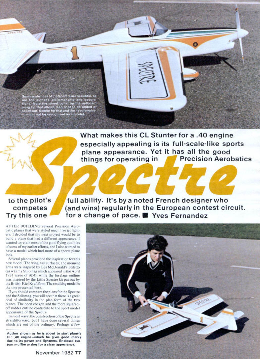
What makes this CL stunter for a .40 engine especially appealing is its full-scale-like sports-plane appearance, yet it retains all the qualities needed for Precision Aerobatics. It's by a noted French designer who competes (and wins) regularly on the European contest circuit. Try this one for a change of pace. — Yves Fernandez
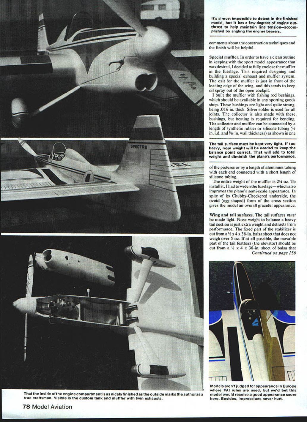
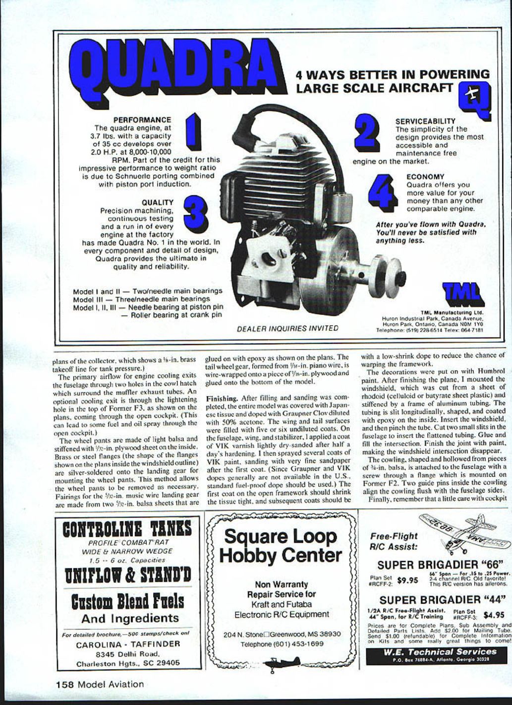
That the inside engine compartment is nicely finished on the outside marks the author as a true craftsman. The visible custom tank, muffler and twin exhausts show the care taken in the installation. Models aren't judged for appearance in Europe under FAI rules, but we'd bet this model would receive a good appearance score. Besides, impressions never hurt.
Background
After building several precision aerobatic planes styled much like jet fighters, I decided my next project would have a different appearance. I wanted to retain the good flying qualities of earlier efforts while giving the model more of a sports-plane look.
Several planes provided inspiration. The wing, tail surfaces, and moment arms were inspired by Les McDonald's Stiletto (as was my Stilomag which appeared in the April 1981 issue of MA), while the fuselage outline was inspired by the Little Spectre kit from the British Kiel-Kraft firm. If you compare the plans for the Spectre and the Stilomag, you will see a great deal of similarity in plan form. The open cockpit and the more squared-off rudder outline contribute to the sport-model appearance of the Spectre.
Construction is largely straightforward, but I used a few nonstandard techniques in the muffler, cooling, and finish that are worth noting.
Special muffler
To preserve the clean sport-model outline I fully enclosed the muffler in the fuselage. The muffler exit is just in front of the wing leading edge, which helps keep oil spray out of the open cockpit.
I built the muffler using fishing-rod bushings (available at sporting-goods shops). These bushings are light and strong, about .016 in. thick. All joints are silver-soldered. The collector is also formed from these bushings and requires heating to bend. The collector and muffler can be connected by:
- a length of synthetic rubber or silicone tubing (1/8 in. i.d., 1/16 in. wall thickness), or
- a length of aluminum tubing with each end joined to the muffler and collector using short lengths of silicone tubing.
(The plans include a drawing of the collector showing a 1/8-in. brass takeoff line for tank pressure.)
The entire muffler weighs 2-1/4 oz. Installing it required widening the fuselage slightly, which also improves the model's semi-scale appearance. In spite of its chubby-cheeked underside, the ovoid (egg-shaped) cross section gives the model a graceful appearance.
Note: the tail surfaces must be kept very light. If too heavy, nose weight will be required to correct the balance, which increases total weight and diminishes performance.
Wing and tail surfaces
Keep the tail surfaces very light. Nose weight to balance a heavy tail is simply extra, unproductive weight.
- The fixed stabilizer is cut from a 1/2 x 4 x 36-in. balsa sheet that does not weigh over 5 oz.
- If possible, the movable elevator should be cut from a 1/2 x 4 x 36-in. balsa sheet that weighs 3-1/2 to 4-1/2 oz, so that the stabilizer and elevator together will not weigh more than 2-1/4 oz with control horn and hinges installed.
- The rudder is fixed but could be made movable or adjustable if desired.
For the wings, choose 1/8-in. balsa sheets that do not weigh more than 1/4 oz. This allows enough thickness for sanding to obtain a very smooth surface. The outboard wing panel is one inch shorter than the inboard panel.
Cooling airflow for the engine primarily exits the fuselage through two holes in the cowl hatch that surround the muffler exhaust tubes. An optional cooling exit is through the lightening hole in the top of former F3 (as shown on the plans), venting through the open cockpit — note this can allow some fuel and oil spray into the cockpit.
Landing gear and wheel pants:
- Wheel pants are made of light balsa and stiffened with 1/32-in. plywood on the inside.
- Brass or steel flanges (as shown on the plans inside the windshield outline) are silver-soldered onto the landing gear for mounting the wheel pants. This allows the pants to be removed as necessary.
- Fairings for the 1/8-in. music-wire landing gear are formed from two 1/8-in. balsa sheets glued with epoxy (see plans).
- The tailwheel gear is formed from 1/16-in. piano wire, wire-wrapped onto a piece of 1/8-in. plywood and glued to the bottom of the model.
Finishing
After filling and sanding, cover the model with Japanese tissue and dope. I used Graupner Clear dope diluted with 50% acetone. The wing and tail surfaces were filled with five or six thinned coats. On the fuselage, wing and stabilizer I applied a coat of VIK varnish, lightly dry-sanded after about half a day's hardening, then sprayed several coats of VIK paint, sanding with very fine sandpaper after the first coat. (Since Graupner and VIK products are generally not available in the U.S., use a standard fuel-proof dope.)
- The first coat on the open framework should be a higher-shrink dope to tighten the tissue; subsequent coats should be low-shrink to reduce the chance of warping the framework.
- Decorations were applied with Humbrol paint.
Windshield: cut from a sheet of celluloid or butyrate plastic and stiffened with a frame of aluminum tubing. The tubing is slit longitudinally, shaped, and coated with epoxy on the inside. Insert the windshield, then pinch the tube. Cut two small slits in the fuselage to insert the flattened tubing, glue and fill the intersection, and finish the joint with paint so the windshield seam disappears.
Cowling: shaped and hollowed from pieces of 3/16-in. balsa and attached to the fuselage with a screw through a flange mounted on former F2. Two guide pins inside the cowling align it flush with the fuselage sides.
Finally, a little care with cockpit detailing adds immeasurably to the plane's appearance.
Flying
The finished model weighs about 56 oz. The lead-out position should be between 18% and 20% of the wing chord. I use an aluminum Veco or Fox spinner. To keep total weight down and avoid unproductive nose weight, take extra care to build the tail very light (stabilizer, elevator, and rudder).
The engine I use is an HP .40 — powerful and lighter than some engines of similar size. The custom muffler is lightweight and mounted well back in the fuselage, which tends to move the center of gravity rearward. With this cooling system and muffler the engine runs well without overheating or power loss. I use a 1/2-in. spraybar.
The Spectre has a very pleasing look. If you build it, I am sure it will give you as much pleasure as it has given me. Happy flying!
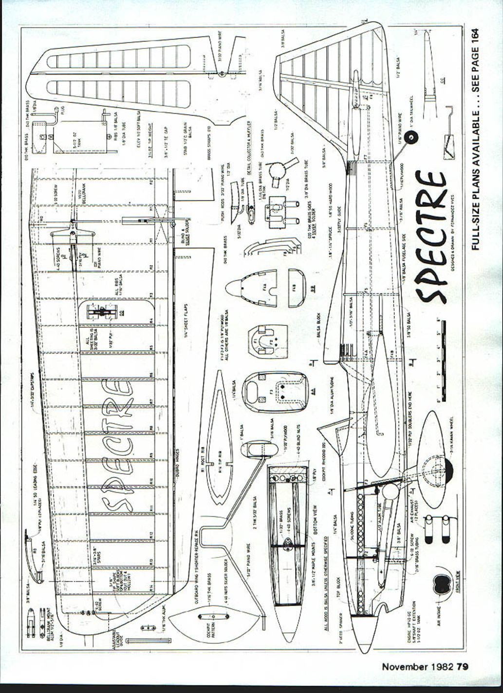
FULL-SIZE PLANS AVAILABLE — SEE PAGE 164
Transcribed from original scans by AI. Minor OCR errors may remain.

