
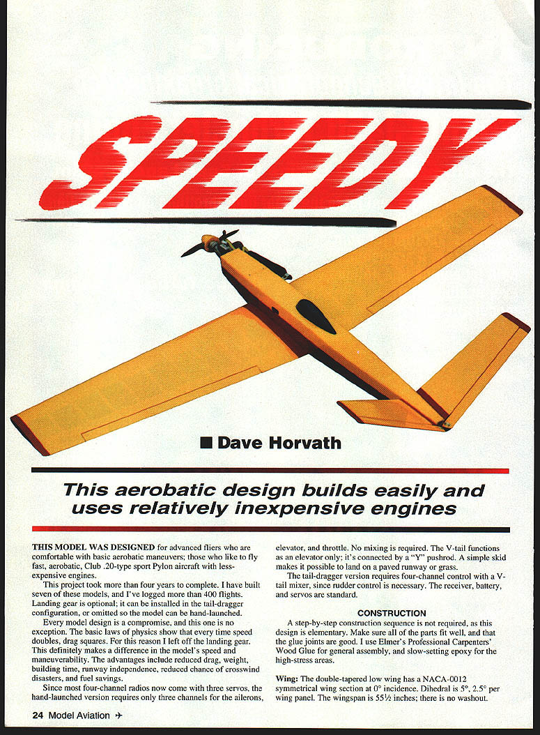
Speedy
Dave Horvath
This aerobatic design builds easily and uses relatively inexpensive engines.
This model was designed for advanced fliers who are comfortable with basic aerobatic maneuvers and who like to fly fast, Club 20–type sport pylon aircraft with less-expensive engines.
I developed this project over more than four years, building seven examples and logging over 400 flights. Landing gear is optional; the model can be built as a tail-dragger (with gear) or as a hand-launched version (without gear). Every design is a compromise: since drag increases with the square of speed, leaving off the landing gear noticeably improves speed and maneuverability. Advantages of the gearless (hand-launch) version include reduced drag and weight, shorter build time, runway independence, reduced crosswind problems, and fuel savings.
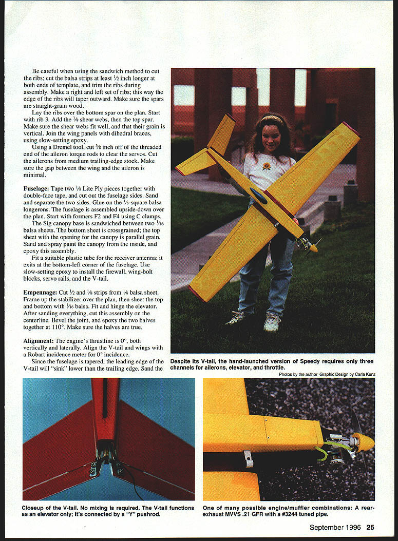
Hand-launched version:
- Requires only three channels (ailerons, elevator, throttle) on most modern radios.
- V-tail functions as elevator only, driven by a "Y" pushrod; no mixing required.
- A simple skid allows landings on paved runways or grass.
Tail-dragger (landing-gear) version:
- Requires four-channel control and a V-tail mixer to provide rudder function.
- Receiver, battery, and servos are standard.
Construction
A step-by-step sequence is not required; the design is elementary. Ensure all parts fit well and glue joints are solid. Recommended adhesives:
- Elmer's Professional Carpenter's Wood Glue for general assembly.
- Slow-setting epoxy for high-stress areas (firewall, wing-bolt blocks, dihedral braces, etc.).
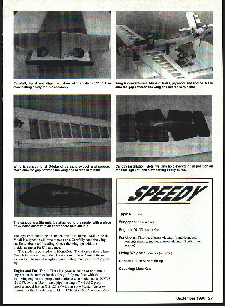
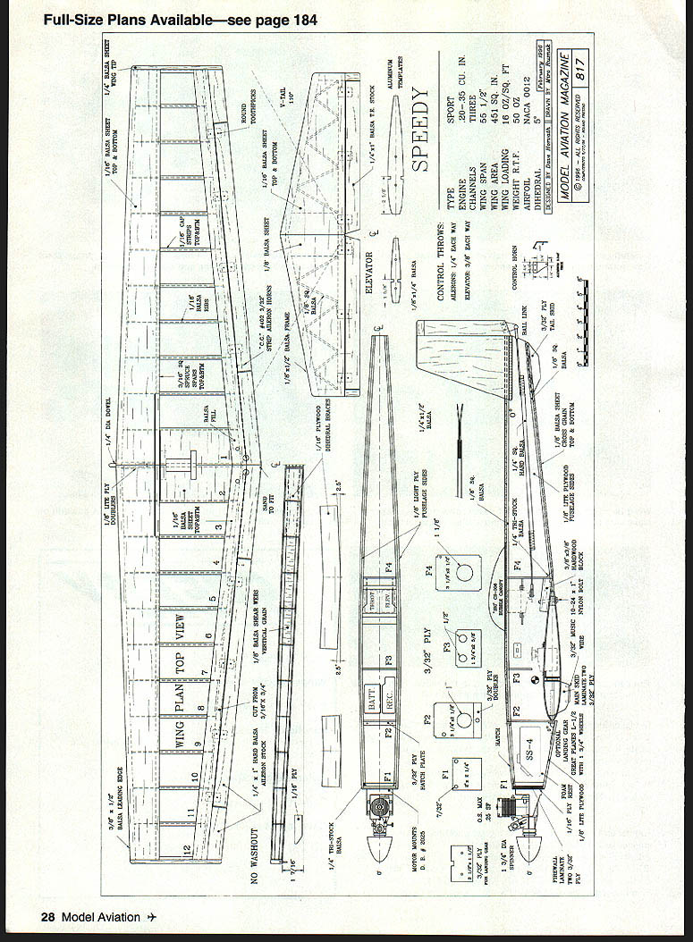
Wing
- Section: NACA 0012 symmetrical.
- Incidence: 0°.
- Dihedral: 5° total (2.5° per panel).
- Wingspan: 55½ inches.
- No washout.
Build using the sandwich method:
- Cut ribs from balsa; cut balsa strips at least 1/2 inch longer than the template and trim ribs during assembly.
- Make right and left sets of ribs so the edge ribs taper outward.
- Use straight-grain spars.
- Lay ribs over the bottom spar on the plan, beginning with rib 3.
- Add shear webs to the top spar (fit with grain vertical).
- Join wing panels and dihedral braces with slow-setting epoxy.
- Using a Dremel tool, cut 3/8 inch off the threaded end of the aileron torque rods to clear the servos.
- Cut ailerons from medium trailing-edge stock and minimize the gap between aileron and wing.
Fuselage
- Tape two 1/8-inch Lite Ply pieces together with double-face tape and cut out the fuselage sides. Sand and separate the two sides.
- Glue 3/16-inch square balsa longerons.
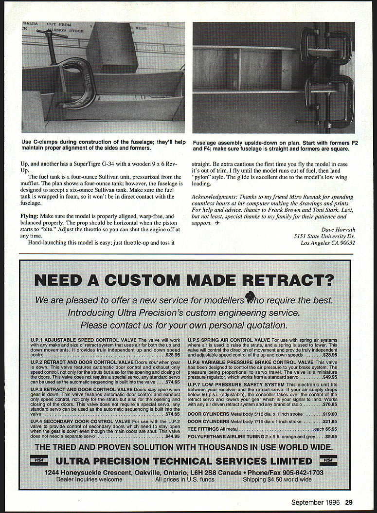
- Assemble the fuselage upside-down over the plan, starting with formers F2 and F4 and using C-clamps as needed.
- Fit the canopy: sandwich the Sig canopy between two 1/16-inch balsa sheets (bottom sheet cross-grained; top sheet with the canopy opening parallel-grained). Sand and spray-paint the canopy from the inside, then epoxy the assembly into place.
- Fit a plastic tube for the receiver antenna to exit the bottom-left corner of the fuselage.
- Install firewall, wing-bolt blocks, and servo rails with slow-setting epoxy.
V-tail Empennage
- Cut strips and frame the stabilizer over the plan; sheet top and bottom with 1/16-inch balsa.
- Fit hinges and the elevator.
- After sanding, cut the assembly on the centerline, bevel the joint, and epoxy the two halves together at approximately 110°. Ensure the halves are true.
Alignment
- Engine thrustline: 0° vertically and laterally.
- Use an incidence meter set to 0° to align the V-tail and wings.
- Because the fuselage tapers at the leading edge, the V-tail leading edge may sit lower than the trailing edge; sand the fuselage sides under the tail until the V-tail reads 0° incidence.
- Ensure the V-tail is aligned in three dimensions.
- Carefully sand the wing saddle for a 0° reading and check wing tips for 0° incidence.
- Covering: MonoKote.
- Recommended control throws (starting point; adjust as needed):
- Ailerons: 3/4-inch each way.
- Elevator: 3/8-inch each way.
- Ready-to-fly weight: approximately 3 pounds (about 50 ounces).
Engine / Fuel Tank
There is a good selection of two-stroke engines suitable for this design. Typical engine/prop combinations I've used:
- MVVS .21 GFR (with #3244 tuned pipe) — 7 x 6 APC prop.
- O.S. .25 SF — 8 x 6 Master Airscrew Scimitar prop.
- O.S. .32 F — 9 x 6 wooden prop.
- SuperTiger G-34 — 9 x 6 Rev-Up wooden prop.
Fuel tank:
- Typical: 4-ounce Sullivan tank pressurized from the muffler (plan shows 4 oz).
- Fuselage will accept a 6-ounce Sullivan tank if desired.
- Wrap the tank in foam so it does not contact the fuselage directly.
Flying
- Before flight, confirm the model is true, warp-free, and properly balanced.
- The prop should be horizontal when the piston begins to "bite."
- Set the throttle so you can shut the engine off reliably.
- Hand-launching: throttle up and toss straight. Be cautious on the first flight in case the model is out of trim.
- I typically fly until the model runs out of fuel, then land "pylon" style. The glide is excellent due to low wing loading.
Specifications
- Type: RC Sport
- Wingspan: 55½ inches
- Engine: .20–.35 two-stroke
- Functions:
- Hand-launched: throttle, aileron, elevator
- Landing-gear version: throttle, rudder, aileron, elevator
- Flying weight: approximately 50 ounces (about 3 pounds)
- Construction: sheet / built-up
- Covering: MonoKote
- Full-size plans available — see page 184
Acknowledgments
Thanks to Miro Rusnak for producing the drawings and prints; to Frank Brown and Toni Stark for help and advice; and to my family for their patience and support.
Dave Horvath 5151 State University Dr. Los Angeles, CA 90032
Transcribed from original scans by AI. Minor OCR errors may remain.

