
SPIRAL STABILITY AND THE BOWL EFFECT
INTRODUCTION
This two-part article addresses spiral stability. The first part describes what is required of an aircraft design to achieve full spiral stability. The conclusion (next month) describes how the bowl-shaped flight path of a circling airplane affects flight behavior. This work is an outgrowth of the four-part series "Dihedral" (August–November 1988, Model Aviation).
Spiral stability refers to a plane's natural ability to hold a trimmed course. This characteristic is crucial to the performance of Free Flight models and to the handling and performance of radio-controlled (RC) sailplanes.
The three key measures that control spiral stability are:
- Equivalent dihedral angle (EDA)
- Vertical stabilizer moment-arm-to-wingspan ratio (lv/b)
- Lift coefficient (Cl)
Define SS ("spiral stability") as: SS = (EDA × lv/b) / Cl
When SS is about 5.7 or greater the plane is almost certain to be spirally stable. Experiments with a typical RC sailplane showed this threshold can be as small as about 4.3 and still preserve spiral stability in some cases.
A simple flight test method to determine spiral stability of RC sailplanes is described below, with test results of a typical two-meter sailplane reported.
Other means of achieving and enhancing spiral stability exist. Common methods employed with Free Flight models incorporate asymmetric wing twist and balance schemes. Mechanical and electromechanical systems may also be used. A successful and possibly novel scheme to stabilize aileron-controlled RC sailplanes is described, including flight tests. This system uses an inexpensive rate gyro to drive the ailerons from a yaw-rate input.
The flight path of circling airplanes is curved. This curvature causes the craft to yaw outboard and pitch down. The amount of yaw and the change in pitch trim are calculated and plotted in Part Two. For Free Flight models the change in pitch trim increases circling speed, reducing Cl and increasing spiral stability. That means unstable models will naturally become stable at some smaller circle radius and higher speed.
What is spiral stability? One of the most important handling and performance criteria for Free Flight models and RC thermal sailplanes, spiral stability describes the ability of an airplane to fly straight and level or to circle without pilot input. A plane with adequate spiral stability will fly indefinitely in a straight line, and when trimmed for a circle will fly that circle without a tendency to tighten up. A plane with little spiral stability will depart from straight flight into a circle and from a circle to a tighter circle — it will "spiral in," hence the term "spiral stability."
Few full-size airplanes are spirally stable at typical lift coefficients. Instead, designers set up the airplane so that the rate of decay from straight flight into a circle is slow enough to be easily prevented by the pilot. Since Free Flight models and good RC sailplanes must be fully spirally stable, Part One (this article) discusses what it takes to achieve this. Part Two will describe what happens when a plane has inadequate spiral stability.
ANALYSIS
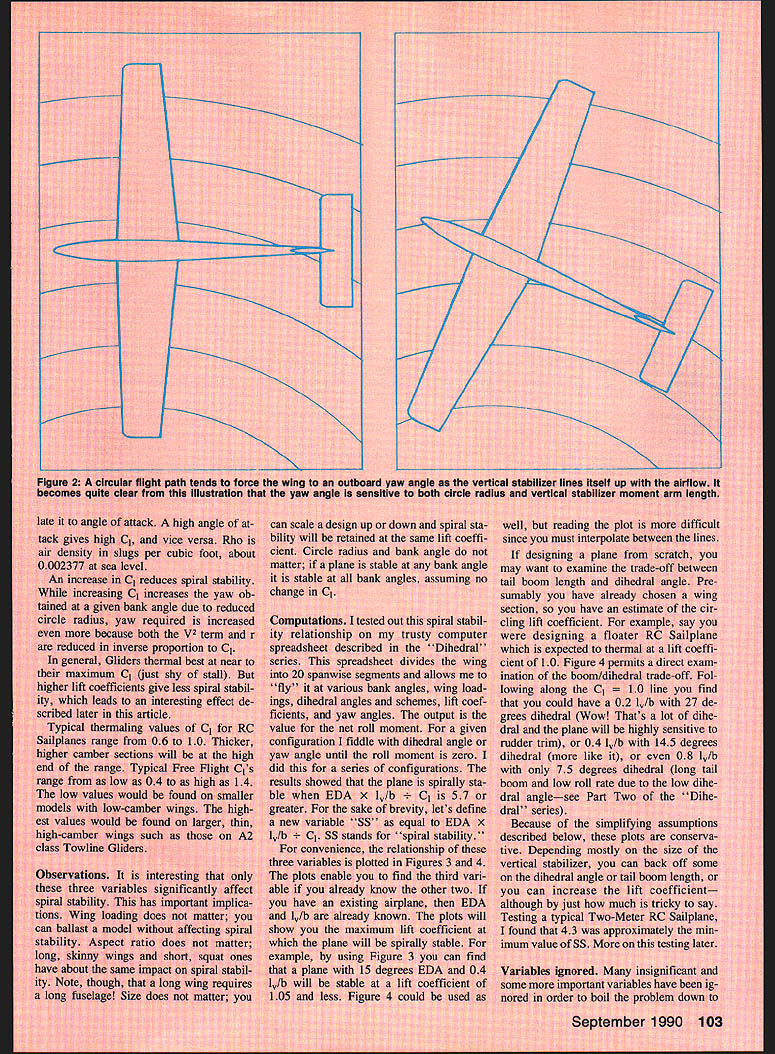
Spiral stability is the result of a balance of rolling moments. While the plane is circling, the extra airspeed on the outboard wing tends to make the craft roll in. Countering this is a natural outboard yaw coupled to dihedral which tends to make the plane roll out. When the airplane is spirally stable, the tendency to roll outboard is greater than or equal to the tendency to roll in.
From the "Dihedral" series we know:
- The yaw angle required to cancel the rolling-in moment at lower bank angles is proportional to (b × W/S) ÷ (V^2 × EDA × r).
- The yaw angle achieved at lower bank angles is proportional to (lv × Cl × sin(bank angle)) ÷ (W/S).
Keeping in mind that circle radius r is proportional to (W/S) ÷ (Cl × sin(bank angle)) and that V^2 is proportional to (W/S) ÷ Cl, the ratio of yaw obtained to yaw required (for lower bank angles) reduces to: yaw obtained / yaw required ∝ (lv/b) × EDA ÷ Cl
Thus the simple crux of this article: SS = (EDA × lv/b) / Cl. The yaw obtained must be equal to or greater than the yaw required for spiral stability. If yaw obtained = yaw required, the plane is neutrally spirally stable. If yaw obtained > yaw required, the plane will roll out of the circle unless bottom rudder is held. If yaw obtained < yaw required, the plane will tighten into the circle unless active top rudder is used.
Anything that increases SS increases spiral stability. The rest of this section examines the three variables in SS.
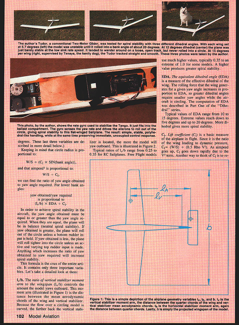
lv/b (vertical stabilizer moment arm / wingspan)
- lv is the distance between the mean aerodynamic chords of the wing and the vertical stabilizer (the vertical stabilizer moment arm).
- The lv/b ratio controls the amount the model yaws outboard while circling. Because the flow over a circling model is curved, the farther back the vertical stabilizer is located, the more the model will yaw outboard.
- Typical lv/b values:
- RC sailplanes: 0.25 to 0.35
- Free Flight models: typically 0.35 up to 1.0 in extreme cases
- A higher lv/b produces greater spiral stability.
EDA (equivalent dihedral angle)
- EDA measures the effective dihedral of the wing; the rolling force generated for a given yaw angle increases in proportion to EDA.
- Typical EDA values:
- Common range: 10° to 15°
- Extreme range: as low as 5° to as high as 20°
- More dihedral (higher EDA) gives more spiral stability.
- The computation of EDA was described in the "Dihedral" series.
Cl (lift coefficient)
- Cl is the lift coefficient, Cl = (W/S) ÷ (0.5 × rho × V^2), where rho is air density (≈ 0.002377 slugs/ft^3 at sea level).
- As airspeed increases, Cl decreases (because of the V^2 term); higher Cl corresponds to higher wing angle-of-attack.
- Higher Cl reduces spiral stability: although it increases the yaw obtained at a given bank angle (via reduced circle radius), it increases the yaw required even more because both V^2 and r change inversely with Cl.
- Typical Cl (thermaling) for RC sailplanes: 0.6 to 1.0. Thicker, high-camber sections use higher values.
- Typical Free Flight Cl: about 0.4 up to 1.4.
- In general, gliders thermal best near maximum Cl (just shy of stall), but higher Cl tends to give less spiral stability.
Observations
- Only three primary variables significantly affect spiral stability: EDA, lv/b, and Cl.
- Important implications:
- Wing loading (W/S) does not directly matter in SS; you can ballast a model without affecting SS if Cl remains the same.
- Aspect ratio does not directly matter to SS.
- Scale (size) does not matter if Cl is retained.
- If a plane is stable at one bank angle (for a given Cl), it will be stable at other bank angles (assuming Cl does not change).
COMPUTATIONS
- A spreadsheet (from the "Dihedral" series) was used to divide the wing into spanwise segments and compute net roll moments for various configurations.
- The spreadsheet results showed that a plane tends to be spirally stable when:
SS = (EDA × lv/b) / Cl ≈ 5.7 or greater.
- For brevity, SS denotes the spiral-stability number.
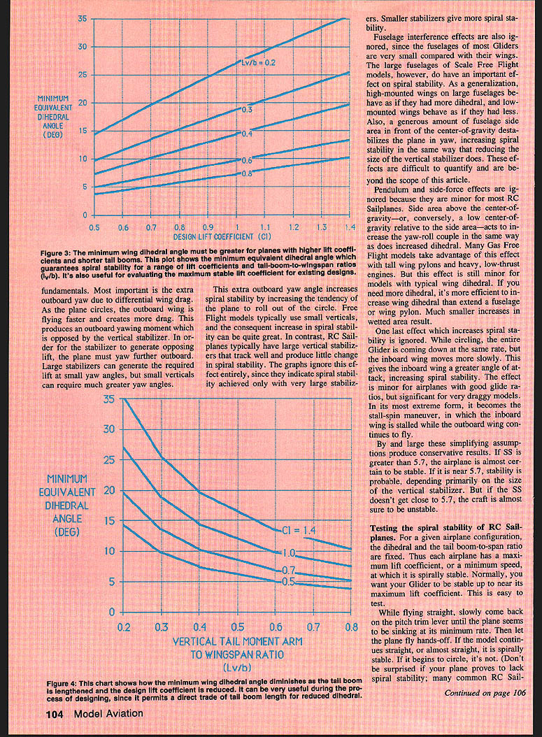
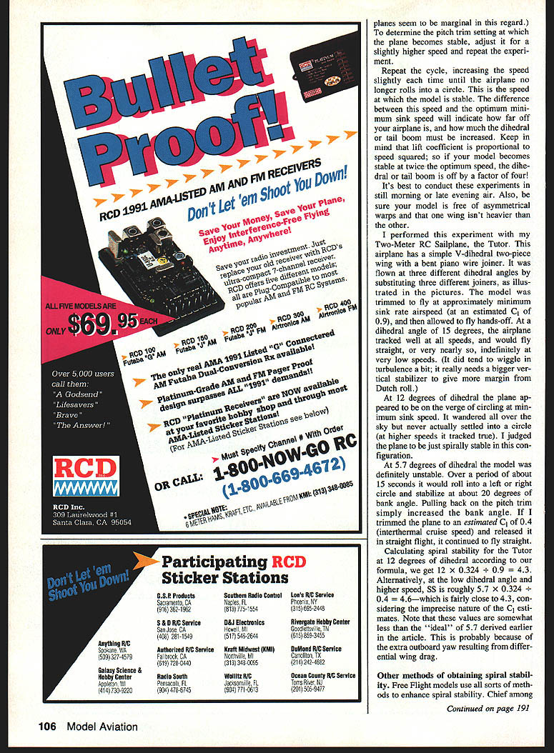
- Plots (Figures 3 and 4 in the original article) show the relation of the three variables and let you determine the third variable if the other two are known. For example:
- A plane with EDA = 15° and lv/b = 0.4 is stable at Cl ≈ 1.05 or less.
- The plots and formula are conservative because several effects (discussed below) were ignored. Depending on vertical stabilizer size and fuselage effects, required dihedral or tail boom length can often be reduced somewhat. Testing of a typical two-meter sailplane indicated SS ≈ 4.3 was approximately the minimum that still produced acceptable spiral stability in that case.
Example calculation (Tutor two-meter sailplane)
- Tutor: lv/b = 0.324
- At EDA = 12°, Cl ≈ 0.9:
SS = (12 × 0.324) / 0.9 ≈ 4.3 (matching flight tests)
- At EDA = 5.7°, Cl ≈ 0.4:
SS = (5.7 × 0.324) / 0.4 ≈ 4.6
- These values are somewhat less than the ideal 5.7 threshold, likely because of additional outboard yaw due to differential drag or aileron trim in actual flight.
VARIABLES IGNORED (simplifying assumptions)
To boil the problem down to fundamentals, several effects were ignored. In general the assumptions produce conservative results (i.e., the calculated SS needed is slightly higher than reality). Key ignored effects:
- Differential wing drag (extra outboard yaw): As the outboard wing flies faster it creates more drag, producing an outboard yawing moment. Small verticals require larger yaw to generate the necessary sideforce, so differential drag can increase spiral stability. Free Flight models often have small verticals and thus can be more stabilized by this effect. The graphs assume large verticals and therefore ignore this added stability; smaller verticals increase SS in practice.
- Fuselage interference: Most glider fuselages are small compared with wings and have minor effect; large fuselages (scale Free Flight models) can be significant. High-mounted wings on large fuselages behave as if they had more dihedral; low-mounted wings behave as if they had less. A lot of fuselage side area forward of the CG destabilizes yaw and increases spiral stability similarly to reducing vertical size. These effects are difficult to quantify here.
- Pendulum and side-force effects: Minor for most RC sailplanes. Side area above the CG or a low CG relative to side area can increase the yaw-roll coupling, similar to increased dihedral. Some gas Free Flight models exploit this via tall pylons and heavy engines, but increasing wing dihedral is usually more efficient.
- Partial stalling of the inboard wing during tight circling can increase spiral stability in some cases.
Overall, if SS > 5.7 the airplane is almost certain to be stable. If SS is near 5.7, stability is probable depending primarily on vertical stabilizer size. If SS is well below 5.7, the craft is almost sure to be unstable.
TESTING SPIRAL STABILITY (flight test procedure)
For a given airplane, EDA and lv/b are fixed; thus each airplane has a maximum Cl (or a minimum speed) at which it is spirally stable. The usual goal is stability up to near maximum Cl (thermaling speed).
Simple flight test procedure:
- Fly straight and slowly come back on the pitch-trim until the plane is sinking at near-minimum rate (near maximum Cl).
- Let the plane fly hands-off.
- If the model continues straight (or almost straight), it is spirally stable at that trim/Cl.
- If it begins to circle, it is not spirally stable.
- To find the trim/speed at which the plane becomes stable, repeat the experiment at slightly higher speeds (less pitch trim) until the airplane no longer rolls into a circle. That is the minimum speed for spiral stability.
- The difference between this speed and the optimum minimum-sink speed indicates how far off your airplane is and how much dihedral or tail boom must be increased. Remember, Cl ∝ 1/V^2, so if your model becomes stable at twice the optimum speed, dihedral or tail boom is off by a factor of four.
Tips:
- Conduct tests in calm conditions (still morning or late-evening air).
- Ensure the model has no asymmetric warps and neither wing is heavier than the other.
- Repeat tests to ensure reliable results.
Tutor flight-test results (author's two-meter sailplane)
- Wing: V-dihedral two-piece wing
- Tested at three dihedral settings and three trim settings
- Trimmed for minimum-sink airspeed (estimated Cl ≈ 0.9)
- Results:
- EDA = 15°: tracked well at all speeds; flew straight (or nearly so) indefinitely at very low speeds. Slight Dutch-roll tendency suggested a larger vertical stabilizer would help.
- EDA = 12°: on the verge of circling at minimum-sink speed; wandered but did not settle into a circle. Judged just spirally stable in that configuration.
- EDA = 5.7°: definitely unstable at minimum-sink Cl ≈ 0.9; over ~15 seconds it would roll into a left or right circle and stabilize at ~20° bank. When trimmed to Cl ≈ 0.4 (interthermal cruise speed) and released, it flew straight.
OTHER METHODS OF OBTAINING SPIRAL STABILITY
Free Flight and RC modelers use various methods beyond dihedral and tail-boom geometry:
- Asymmetric wing twist (washout/washin): Usually inboard wing is washed in and outboard washed out. This is approximately equivalent to yawing a dihedraled wing outboard with rudder trim and can enhance spiral stability (often effective for only one direction of circle).
- Ballast and rudder trim: Adding weight to an inboard wingtip and using outboard rudder trim creates a constant inboard roll and a yaw-roll coupling that can stabilize a single direction of circle. This relies on the bowl effect to increase airspeed and rudder power as the model tightens into the circle.
- Mechanical linkages: Direct mechanical coupling between yaw vanes and ailerons could provide an artificial yaw-roll couple, but such mechanisms can be delicate and require precision.
- Yaw-rate gyro driving ailerons: A rate gyro sensing yaw rate can be used to drive the ailerons to roll the plane out of the circle proportionally to yaw rate. This introduces an artificial yaw-roll couple and can provide spiral stability for low-dihedral aileron-controlled sailplanes. Care must be taken for possible phase issues causing yaw-roll oscillations (Dutch-roll-like).
A caution on low dihedral aileron ships
- Low-dihedral airplanes (e.g., 3°) cannot be spirally stable at reasonable Cl unless they have very long tail-booms (lv/b can have to be > 1.0) or use artificial stabilization.
- For such aircraft, a yaw-roll coupling (mechanical, sensor-driven, or gyro-based) is often the practical solution.
A SUCCESSFUL EXPERIMENT (gyro installation)
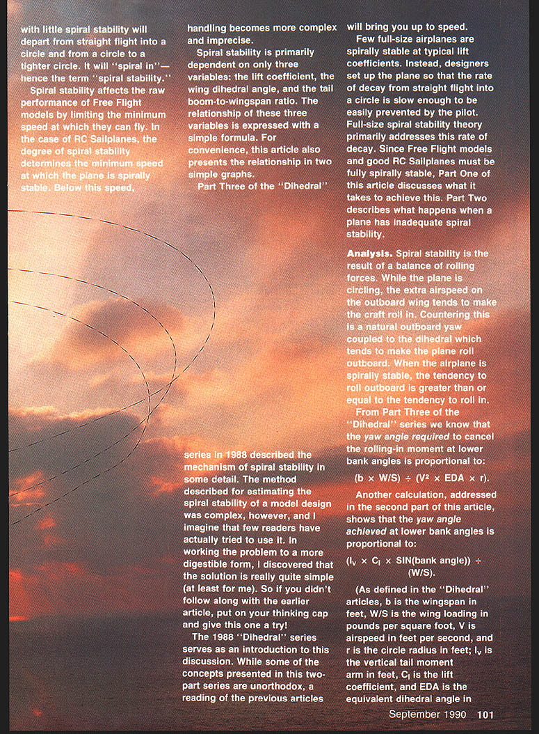
The author tested a rate gyro fix on a large, slow aileron sailplane (the Tango), originally flown with zero dihedral and poor spiral stability.
- Device: Futaba rate-sensitive gyro, model FP-G134 (inexpensive)
- Installation:
- Gyro module placed in-line between the receiver and the aileron servo.
- Rudder servo connected directly to the receiver via a Y-lead so rudder remains unaffected.
- The gyro electronics box has an adjustment screw to vary gyro authority from 0% to 100%.
- The gyro senses yaw rate and commands aileron deflection opposite to yaw rate (to roll the plane out of the turn).
- Results:
- With about 50% sensitivity the Tango flew extremely well: it flew straight indefinitely and straightened out of circles by itself.
- The feel in a circle was similar to a good polyhedral ship but retained immediate aileron roll response.
- No adverse effects were noted through the flight envelope.
- At 100% setting a 1-Hz flat yaw oscillation of about ±15° developed (ascribed to adverse-yaw coupling with the gyro). The model remained flyable but starting at full authority is not recommended—work up to the optimum setting.
This shows that simple, inexpensive rate gyros can provide practical spiral stability for otherwise marginal low-dihedral aileron ships. The gyro does not change aerodynamics but provides closed-loop stabilization.
SUMMARY AND CONCLUSIONS
- Spiral stability measures the tendency of an airplane to "spiral in" from straight or circling flight.
- Primary controlling variables: Equivalent Dihedral Angle (EDA), tail-boom-to-wingspan ratio (lv/b), and lift coefficient (Cl).
- Define SS = (EDA × lv/b) / Cl. In practice:
- SS ≳ 5.7: plane almost certain to be spirally stable.
- SS near 5.7: stability probable, depending on vertical-stabilizer size and fuselage effects.
- SS substantially below 5.7: plane likely unstable.
- Secondary variables: yaw stability due to fuselage proportions and vertical stabilizer sizing; differential drag; partial wing stall; pendulum effects.
- A practical flight test was described to find the minimum speed / maximum Cl for spiral stability.
- Free Flight models often use structural or trim tricks to bias spiral stability for one circle direction.
- Mechanical or electromechanical methods (notably yaw-rate gyros driving ailerons) can provide effective spiral stabilization for aileron-controlled, low-dihedral sailplanes. The author demonstrated a successful gyro installation (Futaba FP-G134) on a slow Tango sailplane.
Next month (Part Two): the effect of circling flight on spiral stability, pitch trim, and yaw angle — including calculations and plots showing how the bowl-shaped flight path changes speed, trim, and stability.
Transcribed from original scans by AI. Minor OCR errors may remain.

