

Spiral Stability and the Bowl Effect
Introduction
Part One of this article described the characteristics required for an airplane to achieve full spiral stability. Part Two explores flight dynamics during circling flight and, in particular, how spiral stability is affected in spirally unstable aircraft.
The principal conclusion of Part One is that an airplane's spiral-stability discriminator, SS — defined as (equivalent dihedral angle) × (vertical-stabilizer moment-arm-to-wingspan ratio) ÷ (lift coefficient) — must be greater than or equal to 5.7 for the craft to be certain of spiral stability. Depending on other variables (especially yaw stability), SS may be reduced to as low as about 4.0 for some configurations.
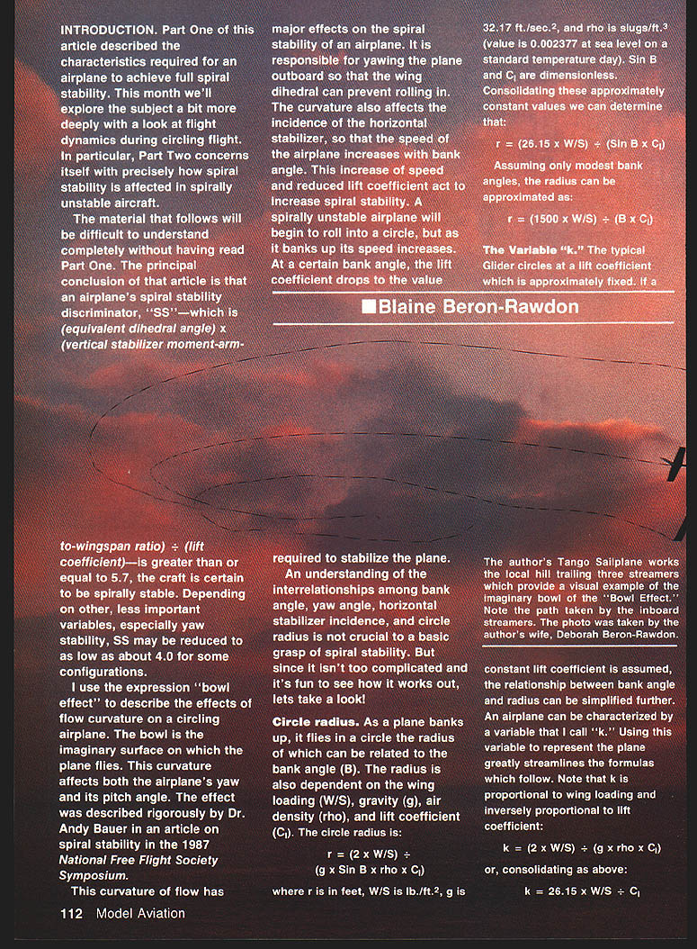
I use the expression "bowl effect" to describe the effects of flow curvature on a circling airplane. The "bowl" is the imaginary surface on which the plane flies; this curvature affects both airplane yaw and pitch. The effect was described rigorously by Dr. Andy Bauer in the 1987 National Free Flight Society Symposium.
Flow curvature yaws the vertical tail outboard (allowing dihedral to prevent rolling in) and changes the incidence of the horizontal stabilizer (causing speed to increase with bank). This speed increase reduces the wing lift coefficient and tends to increase spiral stability. A spirally unstable airplane will begin to roll into a circle; as it banks, speed increases and at some bank the reduced lift coefficient can produce enough stability to stop the spiral.
An understanding of the interrelationships among bank angle, yaw angle, horizontal-stabilizer incidence, and circle radius is not essential for a basic grasp of spiral stability. Still, it is instructive and enjoyable to work through the relationships.
Circle radius
As a plane banks, it flies in a circle whose radius depends on bank angle B, wing loading W/S, gravity g, air density ρ, and lift coefficient C_L. The exact relationship:
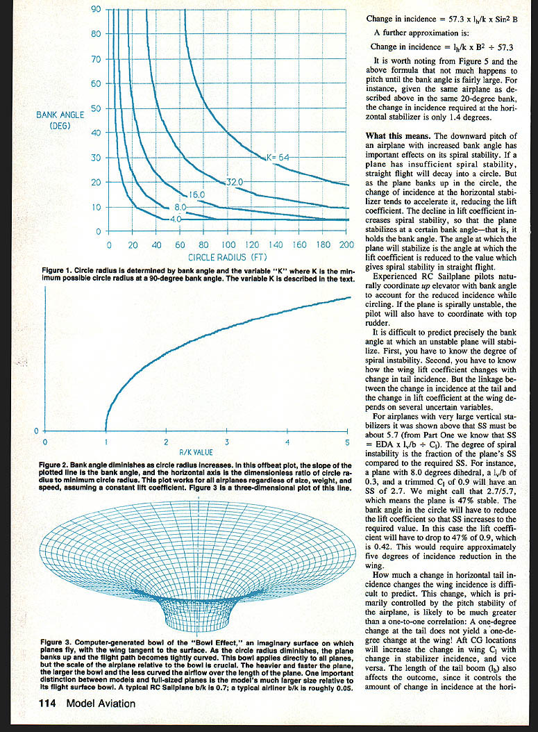
r = (2 × W/S) ÷ (g × sin B × ρ × C_L)
where r is in feet, W/S in lb/ft², g = 32.17 ft/s², and ρ = 0.002377 slugs/ft³ (sea level, standard day). Consolidating constants gives:
r ≈ (26.15 × W/S) ÷ (sin B × C_L)
For modest bank angles an approximate form (using small-angle approximations) is:
r ≈ (1500 × W/S) ÷ (B × C_L)
(Use consistency: B in degrees for this last approximation as presented here.)
The variable k
Define k to simplify formulas; k is proportional to wing loading and inversely proportional to lift coefficient:
k = (2 × W/S) ÷ (g × ρ × C_L)
or, consolidated:
k ≈ 26.15 × (W/S) ÷ C_L
In terms of k:
r = k ÷ sin B
and equivalently:
B = arcsin(k / r)
Typical k values (examples):
- Outdoor rubber free-flight model: k ≈ 4
- Typical RC sailplane: k ≈ 15
- Heavy RC powered model: k ≈ 50
Note: k is also the minimum possible circle radius (when B = 90°), so r_min = k.
The "bowl"
Plotting Y = - ln tan(0.5 × arcsin(k/r)) (where Y is vertical, k/r horizontal) produces a surface which, when revolved about the glide-circle center, represents the bowl — the surface on which the airplane effectively flies. The tangent to this curve at each r/k corresponds to the required airplane bank angle. Alan Sewell derived the formula for this article; direct inquiries about the derivation should be made to him.
As the plane turns in smaller circles (smaller r), bank angle increases rapidly. At B = 90° the minimum radius is r = k.
Outboard yaw
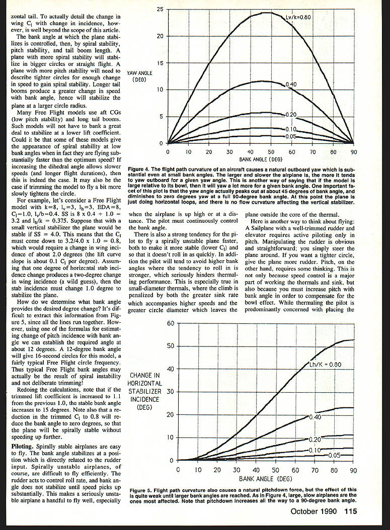
Flow curvature causes the vertical stabilizer to align with the airflow and yaw the wing outboard. Ignoring yaw from differential wing drag, yaw angle can be expressed (with tail moment arm l in feet):
Yaw = arcsin((l / k) × sin B) × cos B
For small bank angles and small l/k:
- Approximation (degrees): Yaw ≈ 57.3 × (l / k) × sin B (converts radians to degrees)
- Further simple approximation for modest banks: Yaw ≈ (l / k) × B (B and Yaw in degrees)
Example: RC sailplane with k = 15 and tail boom l = 3 ft — at B = 20°:
Yaw ≈ (3 / 15) × 20 = 4° (approximate).
Yaw increases with bank angle up to roughly 45°, then decreases to zero at 90° (horizontal loops).
Change in horizontal-stabilizer incidence (pitch effect)
Flow curvature also changes the incidence at the horizontal stabilizer, causing the nose to pitch down as bank increases. With horizontal-stabilizer moment arm l_h in feet:
Change in incidence = arcsin((l_h / k) × sin B) × sin B
Simplified approximations:
- Change ≈ (l_h / k) × sin² B
- For small angles in radians: Change ≈ (l_h / k) × B² (B in radians)
- If B is in degrees, convert: Change ≈ (l_h / k) × (B_deg / 57.3)²
Note: Ensure units (radians vs degrees) are consistent when using the approximations.
Example: Using the earlier RC sailplane (k = 15, l_h = 3 ft), at B = 20° the change in incidence at the horizontal stabilizer is about 1.4° (as illustrated in Figure 5). This downward pitch reduces wing lift coefficient, accelerating the tendency to spiral but also increasing spiral stability via speed-up.
What this means for stabilization
If an airplane has insufficient spiral stability, straight flight will decay into a circle. As the plane banks, the horizontal-stabilizer incidence change tends to reduce wing lift coefficient and increase speed; the reduced C_L increases spiral stability. The airplane will stabilize at the bank angle where the reduced C_L results in the SS required for straight-flight stability.
Predicting the exact stabilizing bank angle is difficult because it depends on:
- Degree of spiral instability (how far SS is below the required value).
- How wing C_L changes with tail incidence, which is governed by pitch stability, center of gravity location, and tail-boom length.
- Change in stabilizer incidence with bank angle (depends on l_h and k).
Typical behavior:
- Longer tail booms produce greater change in stabilizer incidence for a given bank, so they tend to stabilize the plane at larger circle radii.
- Planes with more spiral stability will stabilize in larger circles or fly straight.
- Planes with higher pitch stability require tighter circles (larger bank) before speedup yields sufficient spiral stability.
Example (Free Flight model): Given k = 0.8, l_v = 0.3, l_h = 0.3, equivalent dihedral angle (EDA) = 8°, C_L_trim = 1.0, l_v/b = 0.4:
- SS = EDA × (l_v/b) ÷ C_L = 8 × 0.4 ÷ 1.0 = 3.2
- If required SS = 4.0, then C_L must reduce to (3.2 / 4.0) × 1.0 = 0.8
- With a lift-curve slope ≈ 0.1 C_L per degree, this implies a wing incidence change ≈ 2°
- If 1° change at the horizontal tail produces a 2° wing incidence change (assumption), the tail incidence must change ≈ 1°
- Using the change-of-incidence vs bank-angle relation, this corresponds roughly to B ≈ 12° — giving a typical Free Flight circle frequency
This suggests that some Free Flight bank angles may be the consequence of spiral-instability stabilization (speeding up and reducing C_L), not deliberate trimming.
Piloting implications
- Spirally stable airplanes are easy to fly: bank angle stabilizes relative to rudder input.
- Spirally unstable airplanes are harder to fly efficiently: rudder controls roll rate but bank angle does not stabilize until speed increases. The pilot must continuously control bank angle.
- Pilots tend to fly unstable planes faster (to reduce C_L and slow the roll-in), which impairs thermalling performance: higher speeds increase sink and widen circle diameter, making it harder to stay in the thermal core.
- For sailplanes: rudder is used to steer (circle tighter or looser); elevator must be coordinated with bank angle to offset the bowl effect. The best elevator setting varies with bank angle, so speed control while thermaling requires attention.
If your aircraft has poor spiral stability, you must manage:
- Choosing the best air (thermals, lift)
- Accurate speed control
- Continuous bank-angle control (aileron inputs control roll rate, not steady bank)
Sailplanes with ailerons are especially demanding since ailerons primarily control roll rate; zero aileron does not guarantee zero roll rate in a banked condition.
Future developments (gyro assistance)
The success of gyros in controlling roll for aileron-equipped sailplanes suggests possible extensions:
- A gyro-driven elevator compensation (automatic up-elevator with bank) could counteract the bowl effect. A naive single-direction linear output would produce undesirable down-elevator in the opposite turning direction, but two mitigations are possible:
- A gyro could drive a cam-mixer that provides up-elevator for both turn directions.
- A gyro manufacturer could offer two outputs: a linear one for ailerons and a V-shaped (absolute) one for elevator.
Practical considerations:
- A cam mixer should be prototyped to evaluate effects — yaw excursions or strong required yaw may make the scheme impractical, especially on rudder-and-elevator models.
- On spirally unstable airplanes, gyro elevator input might inhibit the natural speedup that prevents inward spiraling, causing problems.
- Gyro mixing into multiple independent trailing-edge servos could provide spiral stability for complex aileron ships; this is likely achievable by electronics experts.
Further experiments
SS is the primary determinant of spiral stability. For most gliders and RC sailplanes, the other major variable is vertical-tail volume/geometry. A useful experiment would be to test several airplanes and plot required SS against vertical-tail volume, also recording wing section and fuselage proportions. Such data would help designers identify the major determinants of spiral stability and could make a good thesis or science project. I encourage enterprising modelers to pursue this.
Summary and conclusions
- The curved airflow in circling flight (the "bowl effect") causes a model to yaw outboard and pitch down as bank increases. These effects are quantified by the formulas and illustrated in Figures 2–5.
- Pitch-down and consequent speedup while circling reduce wing C_L and increase spiral stability. Spirally unstable airplanes can therefore stabilize at a finite bank angle where the reduced C_L yields the required SS.
- Spirally stable airplanes can be trimmed to fly slowly at any bank angle; spirally unstable airplanes impose an extra piloting task that degrades performance, especially in tight thermals.
- Key parameters affecting stabilization are spiral stability (SS), pitch stability, tail-boom length, and CG location. Longer tail booms and aft CGs (low pitch stability) tend to stabilize at lower bank angles and higher speeds; increased dihedral allows slower, longer flights.
- Practical pilot techniques and possible gyro-based automatic compensation systems can mitigate the bowl effect, but implementation details and trade-offs must be explored experimentally.
Transcribed from original scans by AI. Minor OCR errors may remain.

