
Spirit of the Springs
Evolved over years of flying, this simple-to-build, functional airplane is extremely popular in the Rocky Mountain area, with two local clubs selecting it as a standard design for sport and a special quarter‑midget event. — Jack Aycock
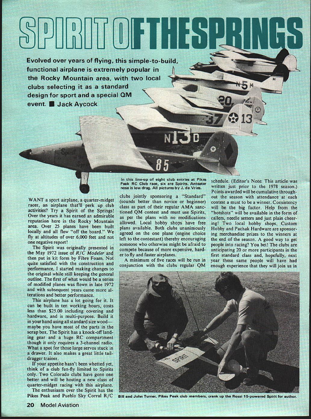
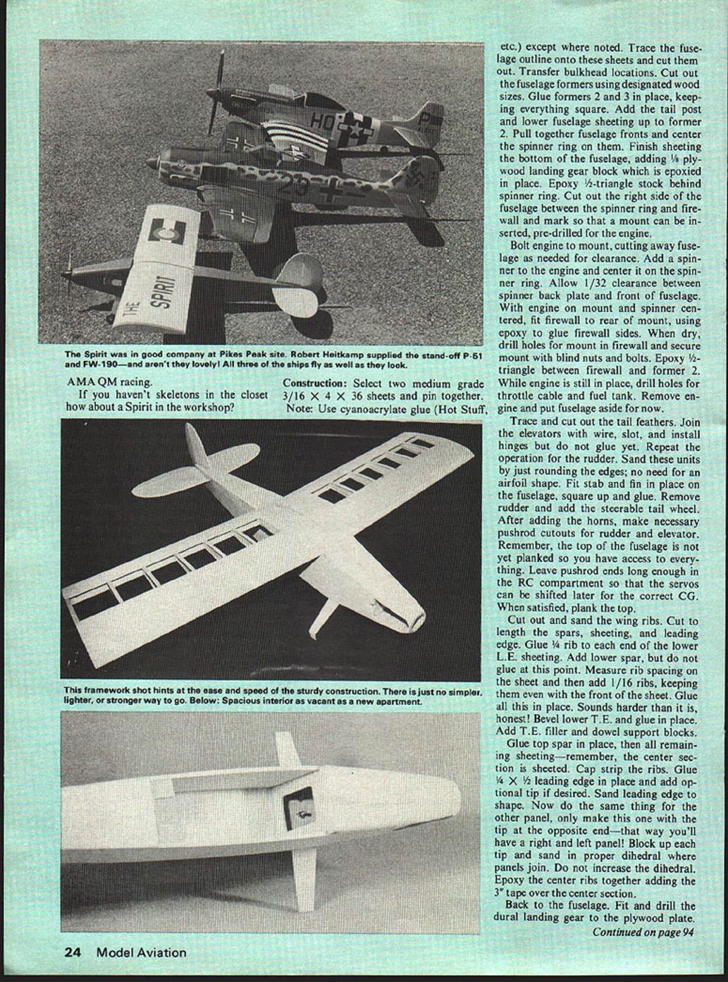
Want a sport airplane, a quarter‑midget racer, an airplane that'll perk up club activities? Try a Spirit of the Springs! Over the years it has earned an admirable reputation here in the Rocky Mountain area. Over 25 planes have been built locally and all flew "off the board." We fly at altitudes of over 6,000 feet and not one negative report.
The Spirit was originally presented in the May 1972 issue of R/C Modeler and then put in kit form by Fibre Foam. Not quite satisfied with the construction and performance, I started making changes to the original while still keeping the general outline. The first of what would be a series of modified planes was flown in late 1972 and with subsequent years came more alterations and better performance.
This airplane has a lot going for it. It can be built in ten working hours, costs less than $25.00 including covering and hardware, and is multi‑purpose. Build it in your hands using all standard size wood—maybe you have most of the parts in the scrap box. The Spirit has a knock‑off landing gear and a huge R/C compartment though it only requires a 3‑channel radio. What a spot for those large servos stuck in a drawer. It also makes a great little tail‑dragger trainer.
Club racing and the "Standard" class
If your appetite hasn't been whetted yet, think of a club fun‑fly limited to Spirits only. Two Colorado clubs have gone one better and will be hosting a new class of quarter‑midget racing with this airplane.
The enthusiasm over the Spirit has the Pikes Peak and Pueblo Sky Corral R/C clubs jointly sponsoring a "Standard" (sounds better than novice or beginner) class as part of their regular AMA‑sanctioned QM contest. Entrants must use Spirits as per the plans with no modifications allowed. Local hobby shops have free plans available. Both clubs unanimously agreed on one plane (engine choice left to the contestant), thereby encouraging someone who otherwise might be afraid to compete because of more expensive, harder‑to‑fly and faster airplanes.
A minimum of five races will be run in conjunction with the clubs' regular QM schedule. (Editor's note: this article was written just prior to the 1978 season.) Points awarded will be cumulative throughout the season with attendance at each contest a must to be a winner. Consistency will be the big factor. Help from the "hotshots" will be available in the form of callers, needle setters and just plain cheering! Two local hobby shops, Custom Hobby and Pachak Hardware, are sponsoring merchandise prizes to the winners at the end of the season. A good way to get people into racing? You bet! The clubs are anticipating 20 or more participants in the first Standard class and, hopefully, next year these same people will have had enough experience that they will join us in other classes.
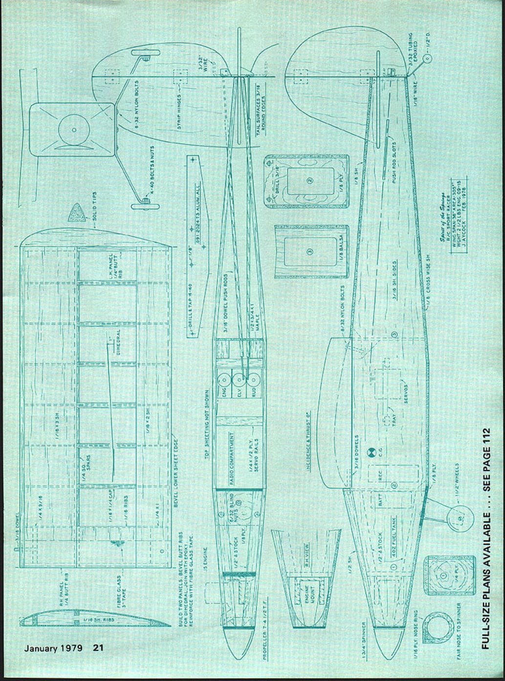
Specifications
- Wing span: 56 in.
- Area: 505 sq. in.
- Type: R/C sport racer
- Weight: 2 1/2 lbs (completed)
- Suggested engine: .09 series (also flown with .15 engines)
- Propeller: 7-1/4 to 7-1/2 in. noted
- Spinner: approx. 1 3/4 in.
- Author/date: Jack Aycock — Feb 1978
Full‑size plans available — see page 112.
Plan callouts / diagram notes
- Top sheeting not shown
- Radio compartment
- Servo rails
- Battery
- Fuel tank
- Blind nuts
- Propeller 7-1/4 in.
- Spinner
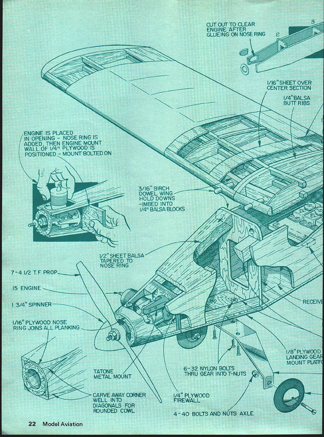
- 1/16" ply nose ring — cut out to clear engine after gluing on nose ring
- 1/16" sheet over center section
- 1/4" balsa butt ribs
- Engine is placed in opening — nose ring is added, then engine mount wall of 1/4" plywood is positioned — mount bolted on
- 3/16" birch dowel wing hold downs — embed into 1/4" balsa blocks
- 1/2" balsa sheet tapered to nose ring
- 7-1/2 in. T.F. prop (noted)
- .15 engine (noted)
- 1 3/4" spinner (noted)
- Tatone metal mount
- Carve away corner well into diagonals for rounded cowl
- 1/4" plywood firewall
- 6-32 nylon bolts thru gear into T‑nuts
- 1/8" plywood landing gear mount plate
- 4-40 bolts and nut axle
- Receiver
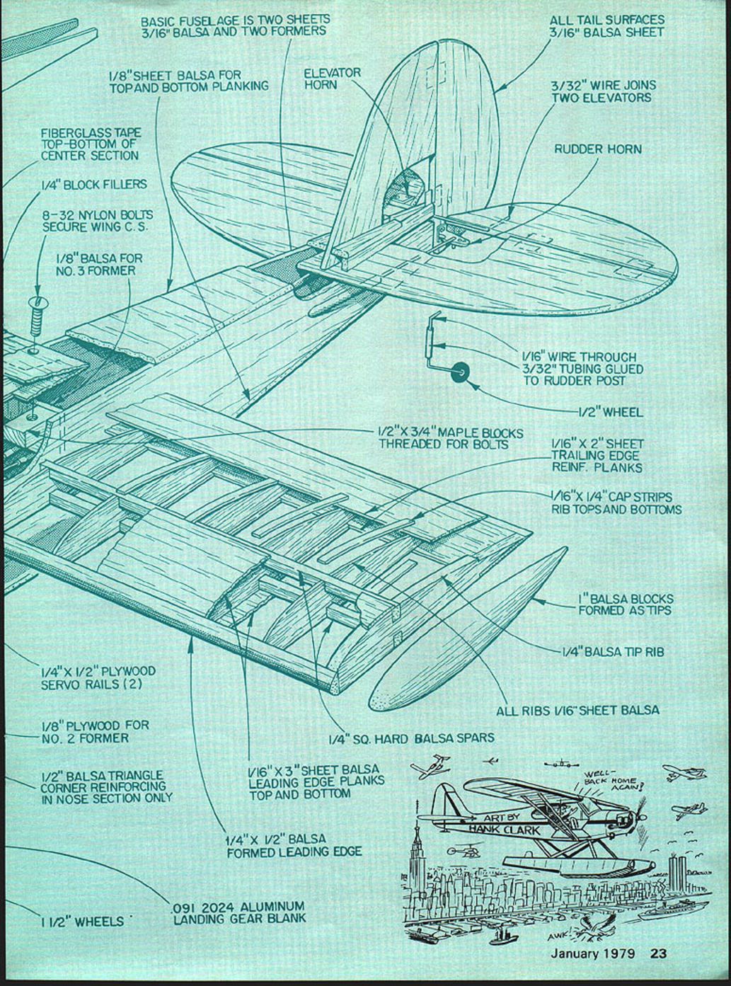
Materials and structural notes
- Basic fuselage: two sheets 3/16" balsa and two formers
- 1/8" sheet balsa for top and bottom planking
- Fiberglass tape top and bottom of center section
- 1/4" block fillers
- 8-32 nylon bolts secure wing center section
- 1/8" balsa for No. 3 former
- 1/4" x 1/2" plywood servo rails (2)
- 1/8" plywood for No. 2 former
- 1/2" balsa triangle corner reinforcing in nose section only
- .091" 2024 aluminum landing gear blank
- 1 1/2" wheels (noted) and 1/2" wheel (also noted for tail)
- Elevator horn; rudder horn
- All tail surfaces: 3/16" balsa sheet
- 3/32" wire joins two elevators
- 1/16" wire through 3/32" tubing glued to rudder post
- 1/2" x 3/4" maple blocks threaded for bolts
- 1/16" x 2" sheet trailing edge reinforcing planks
- 1/16" x 1/4" cap strips for rib tops and bottoms
- 1" balsa blocks formed as tips
- 1/4" balsa tip rib
- All ribs: 1/16" sheet balsa
- 1/4" sq. hard balsa spars
- 1/16" x 3" sheet balsa leading edge planks top and bottom
- 1/4" x 1/2" balsa formed leading edge
Construction
- Select two medium‑grade 3/16" x 4" x 36" sheets and pin them together. Note: use cyanoacrylate glue (Hot Stuff, etc.) except where epoxy is specified.
- Trace the fuselage outline onto these sheets and cut them out. Transfer bulkhead locations. Cut out the fuselage formers using the designated wood sizes.
- Glue formers 2 and 3 in place, keeping everything square. Add the tail post and lower fuselage sheeting up to former 2.
- Pull together the fuselage fronts and center the spinner ring on them. Finish sheeting the bottom of the fuselage, adding the 1/8" plywood landing gear block which is epoxied in place. Epoxy 1/2" triangle stock behind the spinner ring.
- Cut out the right side of the fuselage between the spinner ring and firewall and mark so that a mount can be inserted, pre‑drilled for the engine.
- Bolt engine to mount, cutting away fuselage as needed for clearance. Add a spinner to the engine and center it on the spinner ring. Allow 1/32" clearance between spinner back plate and front of fuselage.
- With the engine on the mount and spinner centered, fit the firewall to the rear of the mount, using epoxy to glue firewall sides. When dry, drill holes for the mount in the firewall and secure the mount with blind nuts and bolts. Epoxy 1/2" triangle between firewall and former 2.
- While the engine is still in place, drill holes for the throttle cable and fuel tank. Remove the engine and set the fuselage aside.
- Trace and cut out the tail feathers. Join the elevators with wire, slot and install hinges but do not glue yet. Repeat for the rudder. Sand these units by just rounding the edges; there is no need for an airfoil shape.
- Fit the stabilizer and fin in place on the fuselage, square up and glue. Remove the rudder and add the steerable tail wheel. After adding the horns, make necessary pushrod cutouts for rudder and elevator. Note: the top of the fuselage is not yet planked so you have access to everything. Leave pushrod ends long enough in the RC compartment so servos can be shifted later for correct CG. When satisfied, plank the top.
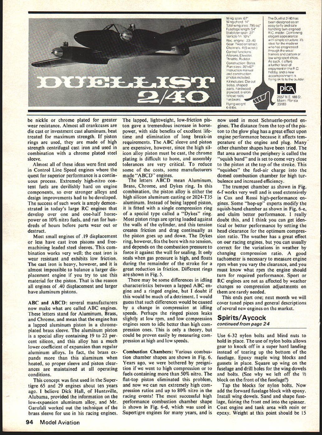
- Cut out and sand the wing ribs. Cut to length the spars, sheeting, and leading edge. Glue a 1/4" rib to each end of the lower leading edge sheeting. Add the lower spar, but do not glue at this point.
- Measure rib spacing on the sheet and then add 1/16" ribs, keeping them even with the front of the sheet. Glue all in place. Bevel the lower trailing edge and glue in place. Add trailing edge filler and dowel support blocks.
- Glue the top spar in place, then all remaining sheeting—remember, the center section is sheeted. Cap‑strip the ribs. Glue 1/4" x 1/2" leading edge in place and add optional tips if desired. Sand the leading edge to shape.
- Repeat for the other panel, making the tip at the opposite end so you'll have a right and left panel. Block up each tip and sand in proper dihedral where panels join. Do not increase the dihedral. Epoxy the center ribs together and add the 3" fiberglass tape over the center section.
- Fit and drill the dural landing gear to the plywood plate. Use 6‑32 nylon bolts and blind nuts to hold it in place—the use of nylon bolts allows the gear to knock off in a hard landing instead of tearing up the bottom of the fuselage.
- Epoxy maple wing blocks and gussets in place. Square up the wing on the fuselage and drill holes for the wing dowels and bolts. Tap the blocks for nylon bolts. Add the forward fuselage block with epoxy and install wing dowels.
- Sand and shape the fuselage, fairing the front end into the spinner. Coat the engine and tank area with resin or epoxy.
- Weight at this point should be about 15 oz.
- Install engine, tank, and spinner. Add R/C gear to locate the CG as shown on the plans. Use 3/8" throw on all surfaces for the first flights. Finish with your favorite iron‑on covering. Don't forget the elevator connecting wire and hinges.
Flying
Flying is a piece of cake. The airplane can be driven down the runway on takeoff like a car. In the air it is very honest and will not do anything you don't ask it to do. Rudder rolls are a snap. In fact, people will want to know where you hid the ailerons! Landing is a dream: just set it up on final and bring it home.
Hope that you too will get as much enjoyment out of the Spirit of the Springs as we have.
Transcribed from original scans by AI. Minor OCR errors may remain.

