
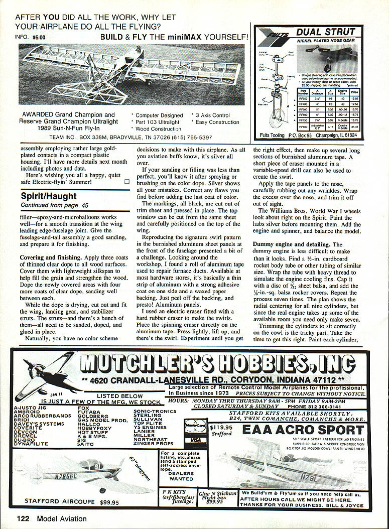
The Spirit of St. Louis
Dave and Michael Haught
For aviation aficionados, the Spirit of St. Louis is one of those airplanes that seems to embody the wonders of flight. Whatever the source of our interest in aviation—airliners, jets, or warbirds of World War I or II—nearly all of us have been touched at one time or another by the Lindbergh legend.
Almost everyone has been attracted to the tall, quiet Lindbergh and his clean, high-wing monoplane, marveling over the man and then the machine. Many of us were fascinated enough to read the book We, maybe even to build a plastic model of the Spirit of St. Louis.
The Lindbergh legend is timeless. The elements of conquest, adventure, and success against great odds bring it alive for each new generation. I fell under the spell of We at the ripe old age of 10, and it has never let me go.
Now my 10-year-old son Michael has been visited by the same spirit. Like his father, and his father's father, he was smitten by airplanes at a very young age.
When Michael was required to read a nonfiction book of his choice recently for school, it was the perfect opportunity to mix learning and fun. Of course he picked We. After he'd read it, we held onto the magic by renting the movie The Spirit of St. Louis, with Jimmy Stewart as Charles Lindbergh. It brought the book so completely to life that by the time we'd finished watching it we were both excited about a possible building project.
Not long afterward we dug out the needed three-view drawings of the airplane that Lindbergh made famous. The Spirit would make a good transition for Michael from 1/2A models to medium-size scale.
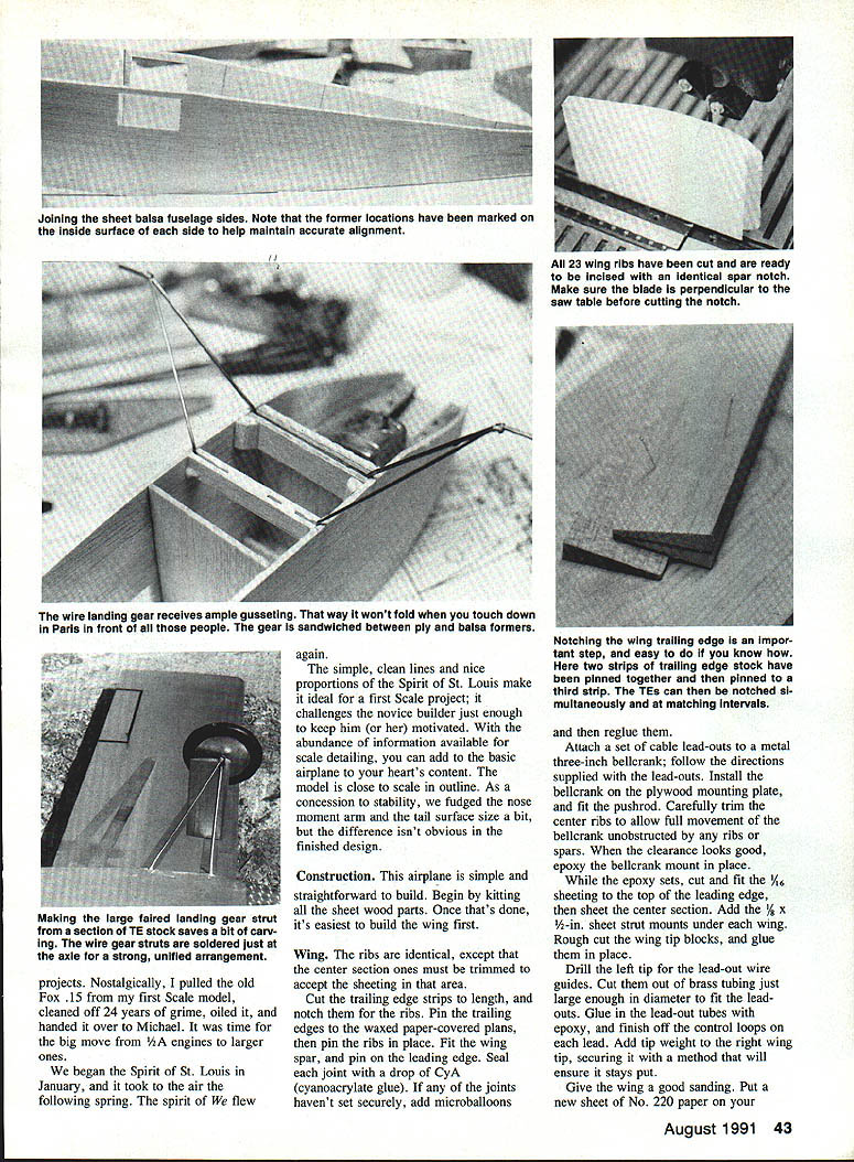
The simple, clean lines and nice proportions of the Spirit of St. Louis make it ideal for a first scale project; it challenges the novice builder just enough to keep him (or her) motivated. With the abundance of information available for scale detailing, you can add to the basic airplane to your heart's content. The model is close to scale in outline. As a concession to stability, we fudged the nose moment arm and the tail surface size a bit, but the difference isn't obvious in the finished design.
Construction
This airplane is simple and straightforward to build. Begin by kitting all the sheet-wood parts. Once that's done, it's easiest to build the wing first.
Wing
The ribs are identical, except that the center-section ones must be trimmed to accept the sheeting in that area.
- Cut the trailing-edge strips to length, and notch them for the ribs. Pin the trailing edges to the waxed-paper-covered plans, then pin the ribs in place.
- Fit the wing spar, and pin on the leading edge. Seal each joint with a drop of CyA (cyanoacrylate) glue. If any joints haven't set securely, add microballoons and reglue.
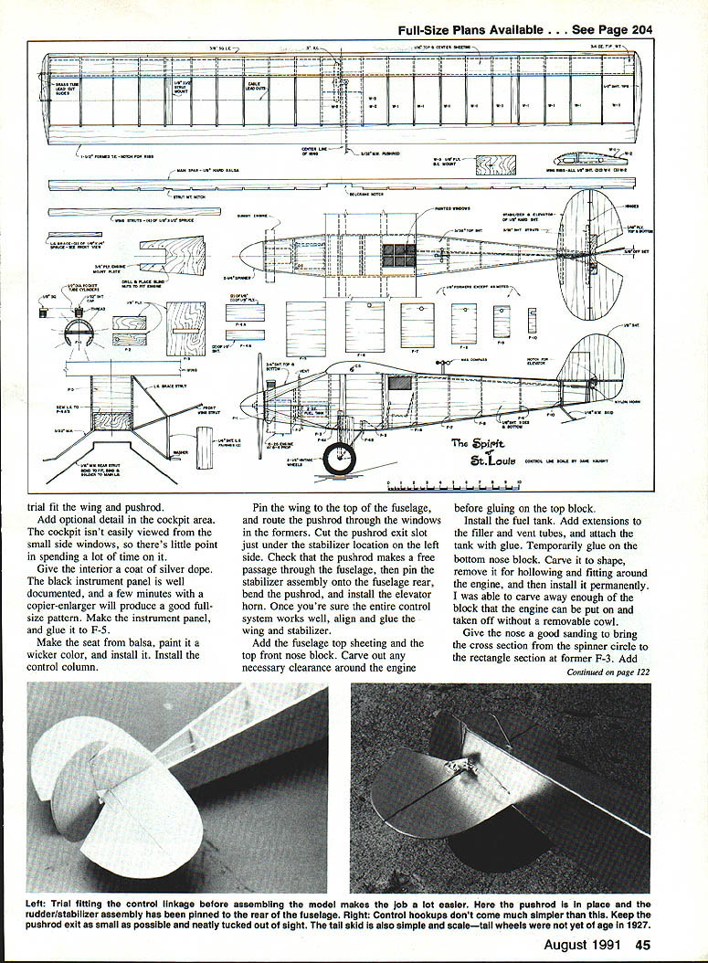
- Attach a set of cable lead-outs to a metal 3-inch bellcrank; follow the directions supplied with the lead-outs. Install the bellcrank on the plywood mounting plate and fit the pushrod. Carefully trim the center ribs to allow full movement of the bellcrank unobstructed by any ribs or spars. When the clearance looks good, epoxy the bellcrank mount in place.
- While the epoxy sets, cut and fit 1/16-in. sheeting to the top of the leading edge, then sheet the center section. Add 1/8 x 1/2-in. sheet strut mounts under each wing. Rough-cut the wingtip blocks and glue them in place.
- Drill the left tip for the lead-out wire guides. Cut the guides from brass tubing just large enough in diameter to fit the lead-outs. Glue the lead-out tubes with epoxy and finish off the control loops in each end.
- Add tip weight to the right wingtip, securing it with a method that will ensure it stays put.
Give the wing a good sanding with No. 220 paper on your sanding block until it's perfect. Blend the leading edge and top sheeting nicely together, and blend in the wingtip blocks.
Finish the wing with three coats of clear dope, sanding well between each. Cover the structure with lightweight silkspan, shrink the silkspan with water, and add four coats of thinned clear dope to fill the pores. Sand the wing lightly between coats with No. 600 paper, and set it aside.
Trial-fit the wing and pushrod.
Empennage
Make the tail surfaces from medium-stiff 3/32-in. sheet balsa. Sand all the edges to a rounded cross section. Glue the rudder and fin together with 3/8-in. of rudder offset to keep the Spirit stable at the end of its lines in flight.
Strengthen the elevator with a plywood sandwich at the center. When the glue has set, hinge the elevator to the stabilizer with your favorite hinges. Lay the stabilizer over the plans, transfer the centerline to its upper surface, and glue on the rudder. Make sure it's congruent with the centerline and perpendicular to the stabilizer when viewed from the front.
Fuselage
The two sheets of 1/8 x 4-in. balsa for the sides may be purchased, or they can be made by edge-laminating two smaller sheets together. Cut the sides to shape and cut out the windows.
If you haven't already done so, this is a good time to cut out all the fuselage formers and parts.
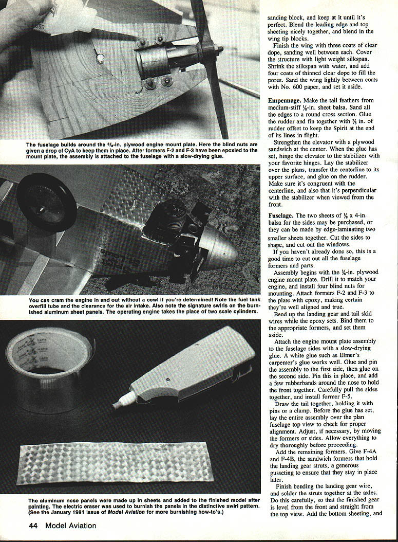
- Assembly begins with the 3/16-in. plywood engine mount plate. Drill it to match your engine and install four blind nuts for mounting. Attach formers F-2 and F-3 to the plate with epoxy, making certain they're well aligned and true.
- Bend up the landing-gear and tail-skid wires while the epoxy sets. Bind them to the appropriate formers and set them aside.
- Attach the engine-mount-plate assembly to the fuselage sides with a slow-drying glue (a white glue such as Elmer's carpenter's glue works well). Glue and pin the assembly to the first side, then glue on the second side. Pin this in place and add a few rubber bands around the nose to hold the front together. Carefully pull the sides together and install former F-5.
- Draw the tail together, holding it with pins or a clamp. Before the glue has set, lay the entire assembly over the plan fuselage top view to check for proper alignment. Adjust if necessary by moving the formers or sides. Allow everything to dry thoroughly before proceeding.
- Add the remaining formers. Give F-4A and F-4B, the sandwich formers that hold the landing gear struts, generous gusseting to ensure they stay in place later.
- Finish bending the landing-gear wire and solder the struts together at the axles. Do this carefully so the finished gear is level from the front and straight from the top view.
- Add the bottom sheeting and sand it with a sanding block until smooth.
Trial-fit the wing and pushrod again.
Add optional detail in the cockpit area. The cockpit isn't easily viewed from the small side windows, so there's little point in spending excessive time on it. Give the interior a coat of silver dope. The black instrument panel is well documented; a few minutes with a copier-enlarger will produce a good full-size pattern. Make the instrument panel and glue it to F-5.
Make the seat from balsa, paint it a wicker color, and install it. Install the control column.
Pin the wing to the top of the fuselage and route the pushrod through the windows in the formers. Cut the pushrod exit slot just under the stabilizer location on the left side. Check that the pushrod makes a free passage through the fuselage, then pin the stabilizer assembly onto the fuselage rear, bend the pushrod, and install the elevator horn. Once you're sure the entire control system works well, align and glue the wing and stabilizer.
Add the fuselage top sheeting and the top front nose block. Carve out any necessary clearance around the engine before gluing on the top block.
Install the fuel tank. Add extensions to the filler and vent tubes and attach the tank with glue. Temporarily glue on the bottom nose block. Carve it to shape, remove it for hollowing and fitting around the engine, then install it permanently. You may be able to carve away enough of the block so the engine can be put on and taken off without a removable cowl.
Give the nose a good sanding to bring the cross section from the spinner circle to the rectangular section at former F-3. Add filler—epoxy and microballoons work well—for a smooth transition at the wing-leading-edge to fuselage joint. Give the fuselage-and-tail assembly a good sanding and prepare it for finishing.
Covering and finishing
Apply three coats of thinned clear dope to all wood surfaces. Cover them with lightweight silkspan to help fill the grain and strengthen the wood. Dope the newly covered areas with four more coats of clear dope, sanding well between each.
While the dope is drying, cut out and fit the wing, landing-gear, and stabilizer struts. The struts all need to be sanded, doped, and glued in place.
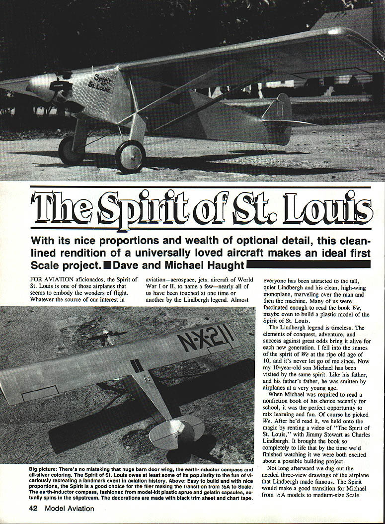
Naturally, you have no color-scheme decisions to make with this airplane: as all you aviation buffs know, it’s silver all over.
If your sanding or filling was less than perfect, you’ll know it after spraying or brushing on the color dope. Silver shows all your mistakes. Correct any flaws you find before adding the last coat of color.
The markings, all black, are cut out of trim sheet and pressed in place. The top window can be cut from the same sheet and carefully positioned on the top of the wing.
Reproducing the signature swirl pattern in the burnished-aluminum panels at the front of the fuselage presented a bit of a challenge. A roll of aluminum tape used to repair furnace ducts works well. Available at most hardware stores, it’s a thin strip of aluminum with a strong adhesive on one side and a waxed-paper backing. Peel off the backing and you have aluminum panels.
I used an electric eraser fitted with a hard rubber eraser to make the swirls. Place the spinning eraser directly on the aluminum tape, press lightly, lift up, and there’s the swirl. Experiment until you get the right effect, then make several long sections of burnished aluminum tape. A short piece of eraser mounted in a variable-speed drill can also be used to create the swirl.
Apply the tape panels to the nose, carefully rubbing out any wrinkles. Wrap the excess over the nose and trim it off out of sight.
The Williams Bros. World War I wheels look about right on the Spirit. Paint the hubs silver before mounting them. Add the engine and spinner, and balance the model.
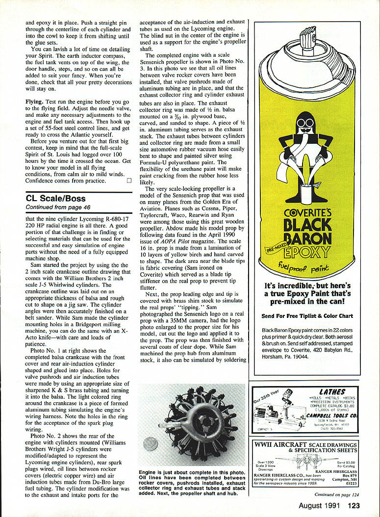
Dummy engine and detailing
The dummy engine is less difficult to make than it looks. Find a 1/2-in. cardboard rocket-body tube or other tubing of similar size. Wrap the tube with heavy thread to simulate the engine cooling fins. Cap it with a disc of 3/32-in. sheet balsa, and add 1/8-in.-sq. balsa rocker covers. Repeat the process seven times. The plan shows the radial centering for all nine cylinders, but since the real engine takes up some of the available room you need only make seven.
Trimming the cylinders to sit correctly on the cowl is the tricky part. Take the time to get this right. Paint each cylinder and epoxy it in place. Push a straight pin through the centerline of each cylinder and into the cowl to keep it from shifting until the glue sets.
You can lavish a lot of time on detailing your Spirit. The earth-inductor compass, the fuel-tank vents on top of the wing, the door handle, knobs, steps, and so on can all be added to suit your fancy. When you're done, check that all your pretty decorations will stay on.
Flying
Test-run the engine before you go to the flying field. Adjust the needle valve and make any necessary adjustments to the engine and fuel-tank access. Then hook up a set of 55-foot steel control lines and get ready to cross the Atlantic yourself.
Before you venture out for that first big contest, keep in mind that the full-scale Spirit of St. Louis had logged over 100 hours by the time it crossed the ocean. Get to know your model in all flying conditions, from calm air to mild winds. Confidence comes from practice.
Transcribed from original scans by AI. Minor OCR errors may remain.

