
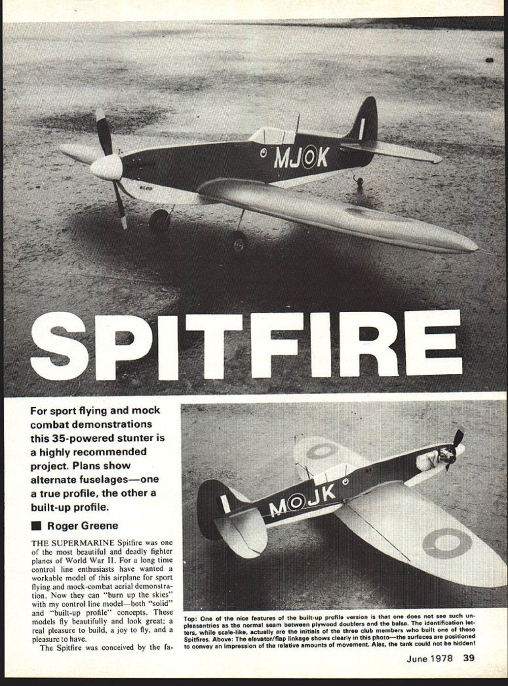
Spitfire
For sport flying and mock combat demonstrations this 35-powered stunter is a highly recommended project. Plans show alternate fuselages—one a true profile, the other a built-up profile.
Roger Greene
THE SUPERMARINE Spitfire was one of the most beautiful and deadly fighter planes of World War II. For a long time control line enthusiasts have wanted a workable model of this airplane for sport flying and mock-combat aerial demonstration. Now they can "burn up the skies" with my control line model—both "solid" and "built-up profile" concepts. These models fly beautifully and look great; a real pleasure to build, a joy to fly, and a pleasure to have.
The Spitfire was conceived by the fa- mous British designer R. J. Mitchell in the mid-1930s. It first flew in 1936. The last Spitfire was made in 1947, closing out the more than 20,300 "Spits" which dominated the skies of Britain during World War II.
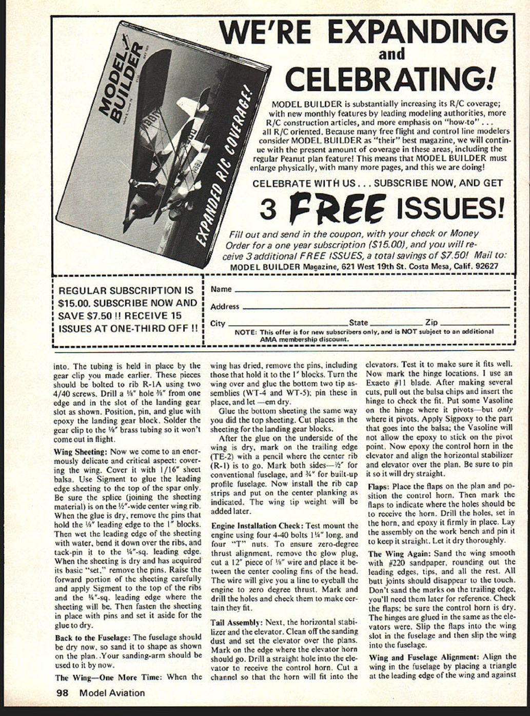
I designed the Spitfires described in this article to fill what I saw as a need—both as a builder and as a stunt flier. In the past, members of the Sky Lancers of Washington, known as the "S.L.O.W. Club," have staged mock aerial combat using various airplanes built from Midwest World War II kits. These are good-sized, with a wingspan of 48 inches, and are usually powered by a Fox .35 engine. The Messerschmitt Me-109 and the P-51 Mustang dominated the mock aerial combat field, and some club members wanted a British model to help "fight" the Me-109.
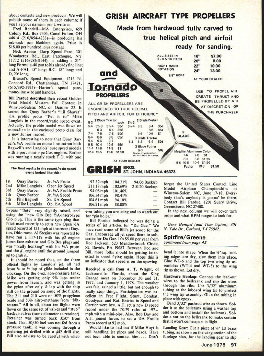
This article describes two Spitfires which can be built on a 50-inch wingspan plan to provide first-class, and historically accurate, competition for the flying Me-109 models. They are a "solid profile fuselage" and a "built-up profile fuselage"—both fly the complete AMA Precision Aerobatic Pattern.
Construction
Study the plans thoroughly before you put your knife to wood. Cut patterns for the individual parts out of the plan, taking care not to cut the spar pattern in half. Use a felt tip pen to trace the patterns on the wood. However, if the Spitfire is to be built by several members of your club you can mount the patterns on some type of sturdy backing. The method I use is to glue the patterns on "gift box" cardboard; it is just about the right strength and weight. Get a large box with handles from a department store.
In studying the building sequence it may seem that we are jumping around a bit, but it has been designed to get the most work done in the least amount of time. By working on one assembly while the glue is drying on another you can get the Spitfire built and on the field sooner.
Begin with the wing spar. Use two sheets of 3/32" balsa as shown on the plan. You'll have to make a splice in the middle, so cut your wood accordingly. Then cut the 1/16" plywood spar doubler which will be glued in front of the full-depth spar. A piece of 3/32" balsa is the rear spar doubler. These doublers are necessary for added strength. Align these pieces over the cardboard-mounted plans, glue, and clamp them for drying.
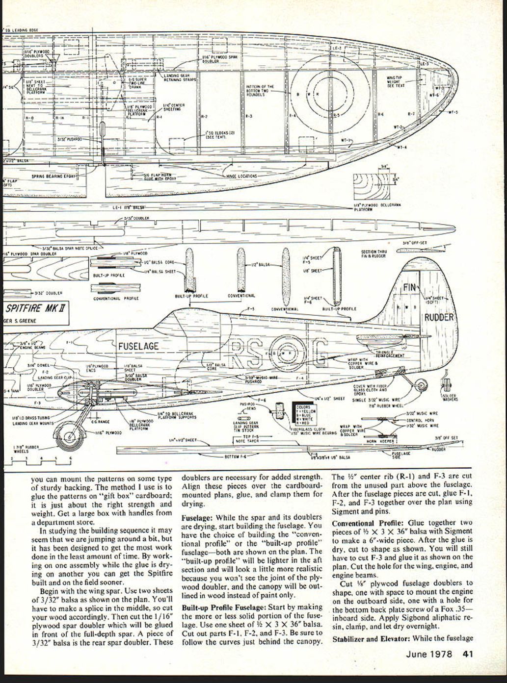
Fuselage:
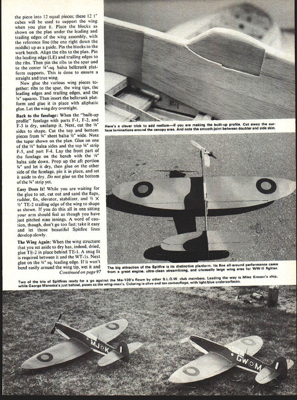
While the spar and its doublers are drying, start building the fuselage. You have the choice of building the "conventional profile" or the "built-up profile" fuselage—both are shown on the plan. The "built-up profile" will be lighter in the aft section and will look a little more realistic because you won't see the joint of the plywood doubler, and the canopy will be outlined in wood instead of paint only.
Built-up Profile Fuselage:
Start by making the more or less solid portion of the fuselage. Use one sheet of 1/2" x 3" x 36" balsa. Cut out parts F-1, F-2, and F-3. Be sure to follow the curves just behind the canopy. The 1/2" center rib (R-1) and F-3 are cut from the unused part above the fuselage. After the fuselage pieces are cut, glue F-1, F-2, and F-3 together over the plan using Sigment and pins.
Conventional Profile:
Glue together two pieces of 1/2" x 3" x 36" balsa with Sigment to make a 6"-wide piece. After the glue is dry, cut to shape as shown. You will still have to cut F-3 and glue it as shown on the plan. Cut the hole for the wing, engine, and engine beams. Cut 1/8" plywood fuselage doublers to shape, one with space to mount the engine on the outboard side, one with a hole for the bottom back plate screw of a Fox .35 inboard side. Apply Sigbond aliphatic resin, clamp, and let dry overnight.
Stabilizer and Elevator:
While the fuselage is drying, cut the horizontal stabilizer and elevator out of 5/16" balsa sheet if available, otherwise use 1/4" balsa sheet (firm). Cut the fin and rudder out of 1/4" balsa (medium). The flaps are cut from 1/4" balsa (soft).
Wing Tips:
The wing tip pieces (WT-1 through WT-6) are cut out of 1/8" balsa sheet. Glue WT-1, WT-2, and WT-3 together; make two assemblies. Glue WT-4 and WT-5 together; make four assemblies.
The wing leading edge (LE-1, LE-2, and LE-3) is cut from 3/8" balsa sheet. LE-1 can be a 3/8" x 1/2" x 36" piece cut to fit. Cut two each of LE-2 and LE-3. Glue LE-1, LE-2, and LE-3 together over the plan.
Cut the trailing edge (TE-1) from 1/8" balsa sheet. TE-2 is sanded from a 1/2" x 1/2" x 36" strip; use a piece that is as straight as possible.
Wing Ribs:
Carve the ribs out of 3/32" balsa. Be sure you make the right number of each rib, and that the cut-outs are correct on each rib. Also make holes for the lead-out wires on the inboard wing panel. Glue the 1/16" plywood doublers on R-1A (see plan).
Built-Up Profile:
After the 1/2"-thick fuselage is dry, you can lighten it by cutting out unneeded portions of the wood. Use a metal lipstick cap or a 1/2" piece of brass tubing as you would a cookie-cutter to cut out the useless balsa weight. Sharpen one end, put a 3/32" x 4" piece of music wire through the side and solder it in place; the wire will act as a handle to help you twist it. With this tool, cut holes 3/4" behind the engine mounts, 1" above the wing, 1/8" below the top of the fuselage, and so forth. Leave at least 1/8" at the rear of the 1/2" sheet.
Glue the 1/8" plywood doublers to the 1/2" balsa fuselage; Sigbond Aliphatic Resin works very well. Be sure that the cut-outs for the engine are on the proper sides of the airplane. Let the fuselage dry overnight. Make a simple wood clamp to glue the doublers: two pieces of 1/4" plywood, and six 2" 6-32 bolts with a washer on each end and a butterfly nut for easy tightening.
The Wing:
Find rib R-1A and drill two 1/8" holes in it for either a Veco landing gear clip, or one of your own making; if you don't have a Veco, make a landing gear clip out of a piece of tin as shown on the plan. The location of the clip is shown in the wing section on the fuselage plan. Hold the spar with the slots up, place R-1 in the center, place R-1A next, and then R-1B. Insert the two 1/4"-sq. bellcrank supports, then place all of the other ribs on the spar in order.
Insert TE-1 and the leading edge assembly (LE-1, LE-2, and LE-3) into the slots in the ribs, then insert both wing tip assemblies (WT-1, WT-2, and WT-3).
A simple wing jig will be necessary to make sure your wing doesn't warp or twist while the glue is setting. Take a piece of balsa 1" square and 12" long. With your felt-tipped marker draw a line along its length, right down the middle. Now cut the piece into 12 equal pieces; these 12 1" cubes will be used to support the wing when you glue it. Place the blocks as shown on the plan under the leading and trailing edges of the wing assembly, with the reference line (the one right down the middle) up as a guide. Pin the blocks to the work bench. Align the ribs to the plan. Pin the leading edge (LE) and trailing edges to the ribs. Then pin the ribs to the spar and to the center 1/4"-sq. balsa bellcrank platform supports. This is done to ensure a straight and true wing.
Now glue the various wing pieces together: ribs to the spar, the wing tips, the leading edges and trailing edges, and the 1/4" squares. Then insert the bellcrank platform and glue it in place with aliphatic glue. Let the wing dry overnight.
Back to the fuselage:
When the "built-up profile" fuselage with parts F-1, F-2, and F-3 is dry, unclamp it. Next, cut the 1/8" sides to shape. Cut the top and bottom pieces from 1/4" sheet balsa 1/2" wide. Note the taper shown on the plan. Glue on one of the 1/8" balsa sides and the top 1/4" strip F-5, and part F-4. Lay the front part of the fuselage on the bench with the 1/4" balsa side down. Prop up the aft portion 1/4" and let it dry, then glue on the other side of the fuselage, pin it in place, and set it aside to dry. Do not glue on the bottom of the 1/4" strip yet.
Easy Does It!
While you are waiting for the glue to set, cut out and sand the flaps, rudder, fin, elevator, stabilizer, and 1/2" x 1/2" TE-2 trailing edge of the wing to shape as shown. If you do this all in one sitting your arm should feel as though you have just pitched nine innings. A word of caution, though, don't go too fast; take it easy and let those beautiful Spitfire lines develop slowly.
The Wing Again:
When the wing structure that you set aside to dry has, indeed, dried, glue TE-2 in place behind TE-1. A snug fit is required between it and the WT-1s. Next glue on the 1/4" sq. leading edge. If it won't bend easily around the wing tip, wet it and bend it into shape. When the 1/4" sq. leading edges are dry, glue them into place. Glue WT-6 and the top two wing tip assemblies (WT-4 and WT-5) to the wing as shown. Let dry.
Hardware Hookup:
Connect the lead-out wires to the bellcrank and slip the wires through the ribs. Use 3/32" aluminum tubing at the inboard wing to protect the wing lead-out assembly. Glue the tubing in place with epoxy.
Bend 3/32" pushrod wire as shown. Solder it to the bellcrank using a washer top and bottom and install the bellcrank. Solder a nut on the bellcrank to make certain that it won't come apart in flight.
Landing Gear:
Cut a piece of 1/8" ID brass tubing, as shown on the wing section of the fuselage plan, for the landing gear to slip into. The tubing is held in place by the gear clip you made earlier. These pieces should be bolted to rib R-1A using two 4/40 screws. Drill a 1/8" hole 3/4" from one edge and in the slot of the landing gear slot as shown. Position, pin, and glue with epoxy the landing gear block. Solder the gear clip to the 1/8" brass tubing so it won't come out in flight.
Wing Sheeting:
Now we come to an enormously delicate and critical aspect: covering the wing. Cover it with 1/16" sheet balsa. Use Sigment to glue the leading edge sheeting to the top of the spar only. Be sure the splice (joining the sheeting material) is on the 1/2"-wide center wing rib. When the glue is dry, remove the pins that hold the 1/4" leading edge to the 1/2" blocks. Then wet the leading edge of the sheeting, bend it down over the ribs, and tack-pin it to the 1/4"-sq. leading edge. When the sheeting is dry and has acquired its basic "set," remove the pins. Raise the forward portion of the sheeting carefully and apply Sigment to the top of the ribs and the 1/4"-sq. leading edge where the sheeting will be. Then fasten the sheeting in place with pins and set it aside for the glue to dry.
Back to the Fuselage:
The fuselage should be dry now, so sand it to shape as shown on the plan. Your sanding-arm should be used to it by now.
The Wing—One More Time:
When the wing has dried, remove the pins, including those that hold it to the 1/2" blocks. Turn the wing over and glue the bottom two tip assemblies (WT-4 and WT-5); pin these in place, and let them dry.
Glue the bottom sheeting the same way you did the top sheeting. Cut places in the sheeting for the landing gear blocks.
After the glue on the underside of the wing is dry, mark on the trailing edge (TE-2) with a pencil where the center rib (R-1) is to go. Mark both sides—1/2" for conventional fuselage, and 3/4" for built-up profile fuselage. Now install the rib cap strips and put on the center planking as indicated. The wing tip weight will be added later.
Engine Installation Check:
Test mount the engine using four 4-40 bolts 1-1/4" long, and four "T" nuts. To ensure zero-degree thrust alignment, remove the glow plug, cut a 12" piece of #8 wire and place it between the center cooling fins of the head. The wire will give you a line to eyeball the engine to zero degree thrust. Mark and drill the holes and check them to make certain they fit.
Tail Assembly:
Next, the horizontal stabilizer and the elevator. Clean off the sanding dust and set the elevator over the plans. Mark on the edge where the elevator horn should go. Drill a straight hole into the elevator to receive the control horn. Cut a channel so that the horn will fit into the elevator. Test it to make sure it fits well. Now mark the hinge locations. I use an Exacto #11 blade. After making several cuts, pull out the balsa chips and insert the hinge to check the fit. Put some Vaseline on the hinge where it pivots—but only where it pivots. Apply Sigpoxy to the part that goes into the balsa; the Vasoline will not allow the epoxy to stick on the pivot point. Now epoxy the control horn in the elevator and align the horizontal stabilizer and elevator over the plan. Be sure to pin it so it will dry straight.
Flaps:
Place the flaps on the plan and position the control horn. Then mark the flaps to indicate where the holes should be to receive the horn. Drill the holes, set in the horn, and epoxy it firmly in place. Lay the assembly on the work bench and pin it to keep it straight. Let it dry thoroughly.
The Wing Again:
Sand the wing smooth with #220 sandpaper, rounding out the leading edges, tips, and all the rest. All butt joints should disappear to the touch. Don't sand the marks on the trailing edge; you'll need them later for reference. Check the flaps; be sure the control horn is dry. The hinges are glued in the same manner as the elevators were. Slip the flaps into the wing slot in the fuselage and then slip the wing into the fuselage.
Wing and Fuselage Alignment:
Align the wing in the fuselage by placing a triangle at the leading edge of the wing and against the fuselage. Place a straightedge on the trailing edge and adjust the wing until it is in line with the fuselage. When it is perfectly positioned, glue the wing hold-down blocks in place and pin until dry. Install the bellcrank in the fuselage and connect the pushrod to the elevator. Check to see that the elevator moves equally up and down. If not, adjust the linkage until it does.
Rigging the Controls:
Run the lead-out wires through the wing and attach to the bellcrank. Use 3/32" aluminum tubing at the inboard wing to protect the lead-out assembly. Glue the tubing in place with epoxy. Bend 3/32" pushrod wire as shown. Solder it to the bellcrank using a washer top and bottom and install the bellcrank. Solder a nut on the bellcrank to make certain that it won't come apart in flight.
Final hook-ups for throttle and other linkages should be made, checked for free movement, and secured. Balance the model to the recommended center of gravity and make any final adjustments to control throws before finishing and flying. the fuselage—the wing is straight there. Make sure that the trailing edge marks on the wing are still seen on both sides of the fuselage. Also with the triangle make sure the fuselage is 90° to the airfoil opposite the canopy. Epoxy and let it dry overnight.
Drill and insert two 3/16" dowels as shown. Glue with epoxy or Sigbond. Now put on the bottom fuselage cap (F-6). Glue it into place with Sigbond. Glue the flap hinges on the trailing edge (TE-2) of the wing in the same way as you handled the stabilizer and elevator.
Tail Alignment:
Horizontal stabilizer and elevator are next to be glued into the fuselage. Mark the fuselage width on the center of the leading edge of the stabilizer and insert it into the fuselage, using the marks to make certain it is exactly centered. Glue it with Sigbond. Use the 1/2" triangular piece glued under each side of the stabilizer for extra strength. The horizontal stabilizer should be parallel with the wing. Stand a couple of feet away and eyeball it from the front: align the top of the wing with the bottom of the stabilizer.
Be sure the horizontal stabilizer hinge line is exactly parallel with the wing hinge line. Measure this distance from the hinge line at the tip of the stabilizer to the trailing edge of the wing hinge line on both sides. These distances must be equal or the airplane won't track properly or fly at the proper horizontal altitude.
After the surfaces are straight and true, let the whole thing dry thoroughly. Every hour or so check to make sure that the surfaces are still aligned properly, but give it plenty of time to set.
The fin and rudder are glued on next. Use rudder offset as shown on the plan.
Landing Gear:
Bend the landing gear shape as shown on the plan, making sure to make a left and a right. Be sure, also, to match the sweep-forward shown on the plan. To fasten the wheels on, slip the wheel over the axle, then a washer, and then take a couple of turns of copper wire around the axle, and solder the wire and the washer to the axle.
Place the main landing gear in the mounts in the wing, using Sig landing gear straps to secure it in place. Bend and epoxy the tail wheel strut on as shown. Secure the wheel the same way as the main gear.
Connecting Flaps and Elevator:
The easy way to connect the flaps and elevator is with two pieces of 3/32" music wire long enough to overlap each other, about 1" or 1-1/2", as shown. Wrap with copper wire. When pushrods are bent and installed with keepers, flaps and elevators should be set at zero degrees. Solder the pushrod. Put a pushrod bearing about halfway between the elevator and the flaps (see plan).
Fuel Tank:
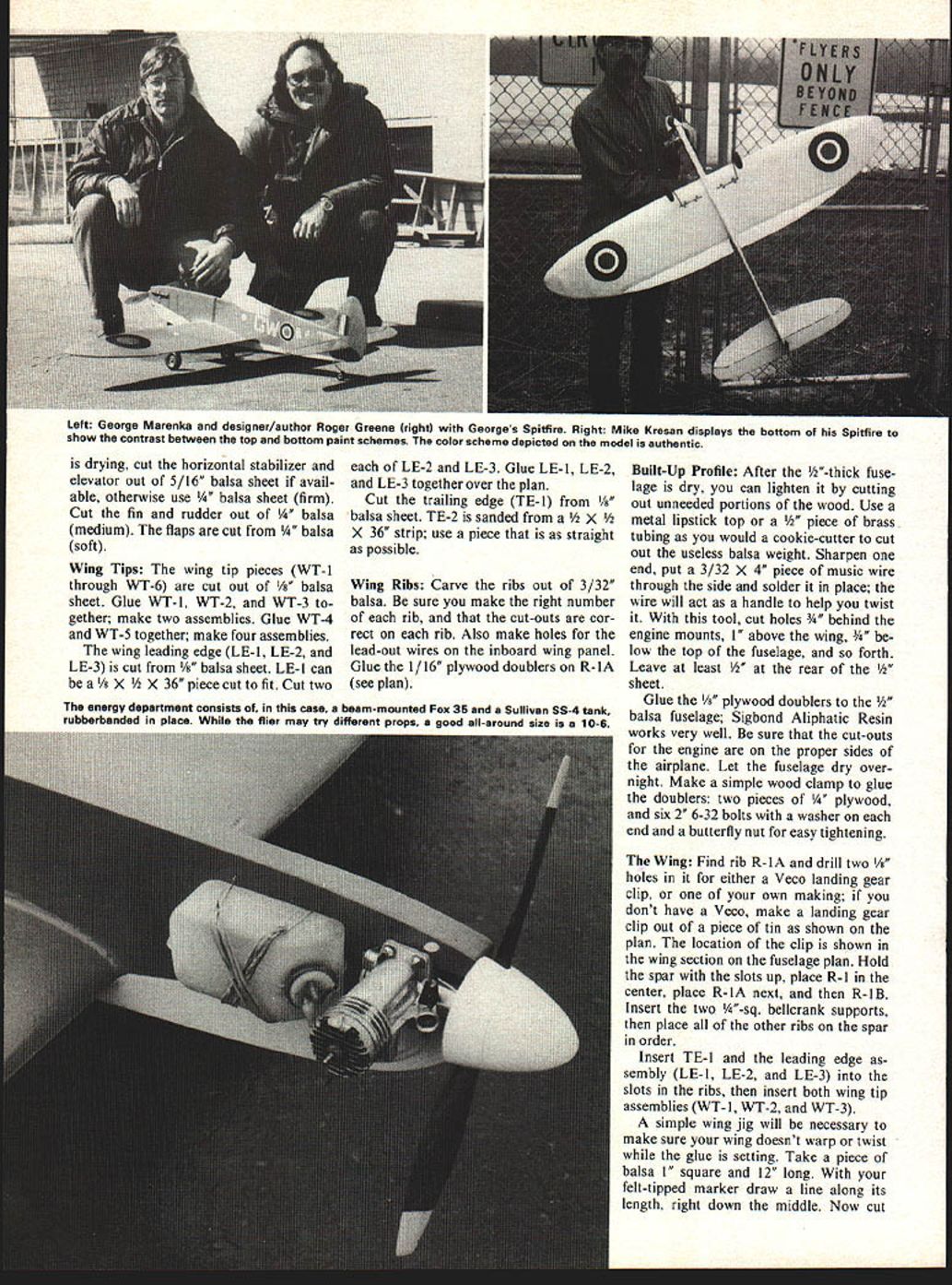
Mount the fuel tank on the fuselage using music wire and rubber-bands. Use a Sullivan 4 oz. tank (see picture).
Wing Tip Weight:
With the engine installed, turn the airplane over on its rudder and nose. The inboard wing should touch the table. Apply enough weight to allow the outboard tip to flop down on the workbench; the inboard tip will be up. This is enough weight. Lead or solder wrapped with light string makes a good weight; epoxy it to the wood.
Leadouts:
If you haven't done so already (some people like to get ahead of the plan), wrap the leadouts (see plan).
Finishing:
After test-fitting the fuel tank and engine—and with the wing tip weight installed—fine-sand the entire airplane to a "baby's bottom" smoothness. Paint it with two coats of clear dope. When both coats are dry and hard, sand the whole airplane again with fine sandpaper—but lightly. The clear dope over the whole model will keep the wood grain from rising under the covering.
Cut Silkspon to shape over the wing and wet it with water using a mist sprayer. Pull the Silkspon around the leading edges to remove wrinkles. Cement the Silkspon to the wing by applying clear dope to the center planking, leading edges, trailing edges, and wing tips, continually pulling the entire wing to keep wrinkles out. When the Silkspon is dry, paint the entire wing with six (6) coats of clear dope, sanding very lightly after each even-numbered coat. Use two coats of sanding sealer over the entire airplane to fill the wood grain, then apply the final color coats as desired.
Markings:
The roundels on each wing are placed as shown on the plan; the top ones are shown on the inboard side, the bottom ones are shown on the outboard side.
Here's a good, easy way to make them turn out right: using a compass, draw the proper circles on contact paper and cut them out. Starting with the center, paint the area of each roundel on the wing—a little more than the actual area will be on the finished airplane. Then cover the area with the contact paper mask for the center circle. Seal the edges with clear paint. Paint the next color, again a little larger than the actual roundel will be, and cover it with the proper mask and seal the edges with clear paint. Continue this until the roundel is complete. Leave the paper on until the rest of the Spitfire is painted. Then peel off the contact paper and, presto, you've got a professional job. It may seem faster to do all of them at the same time, but just make sure you put the right color on the right circles.
Paint the canopy a light blue. Add your AMA numbers. Your initials can go on the fuselage.
Paint the bottom of the airplane light blue; paint the top with olive and tan camouflage colors.
Conclusion: Both of our Spitfires needed the back plate of the engine filled with solder to be trimmed to fly. In the May, June and July 1976 issues of Model Aviation, Chris Lella tells a lot about your airplane's actions and problems in the articles on balancing for roll, yaw and pitch on control line stunt ships. These are quite good and should be read by every control line flyer.
The models described in this article are both capable of doing the complete AMA pattern without any problems. With either of them you have a worthy addition to your stable of acrobatic and mock-combat champions.
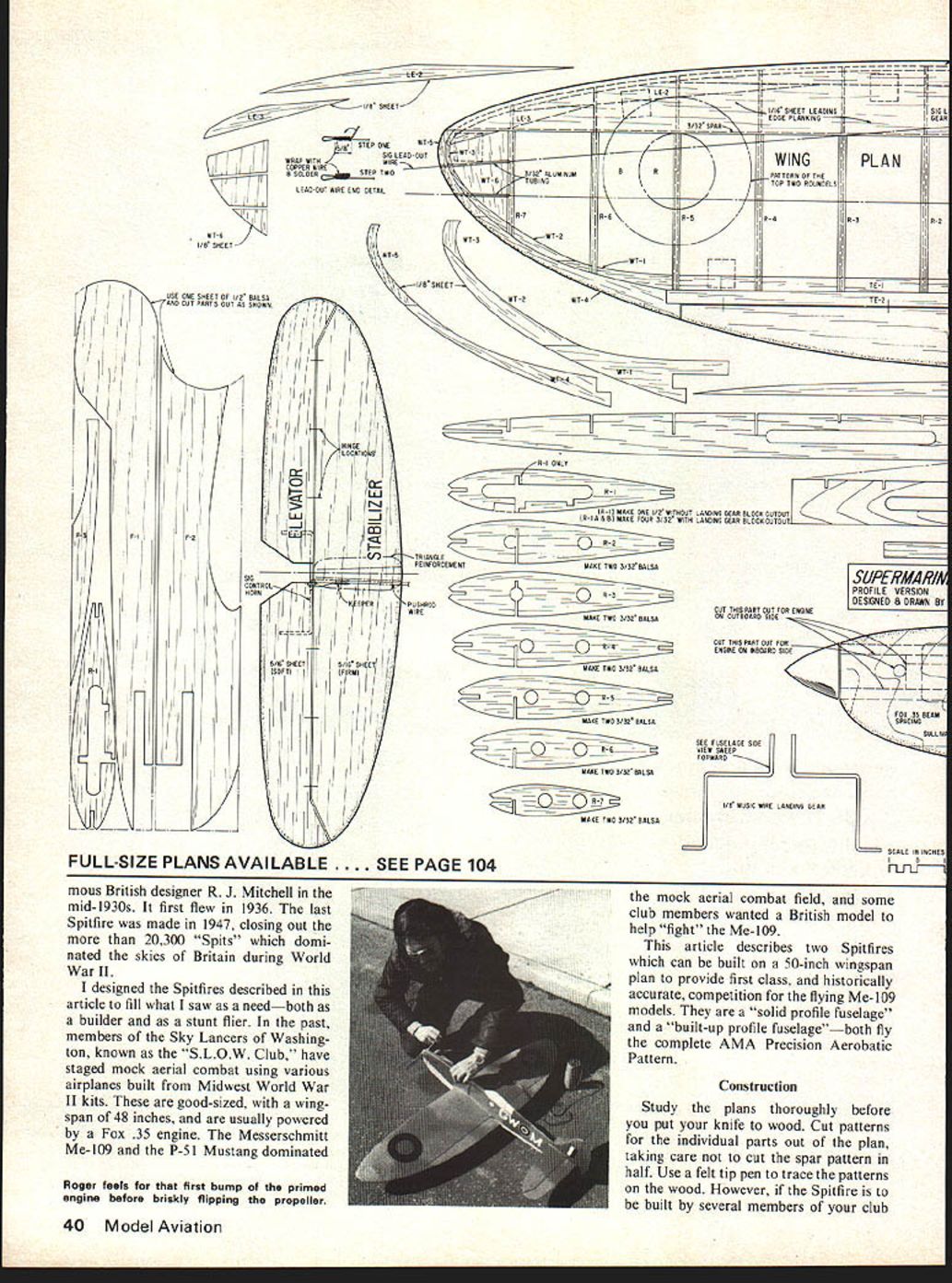
Transcribed from original scans by AI. Minor OCR errors may remain.

