
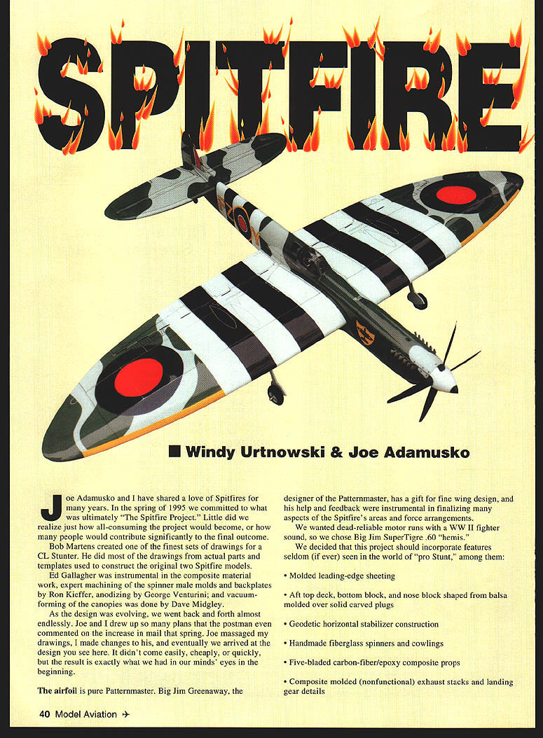
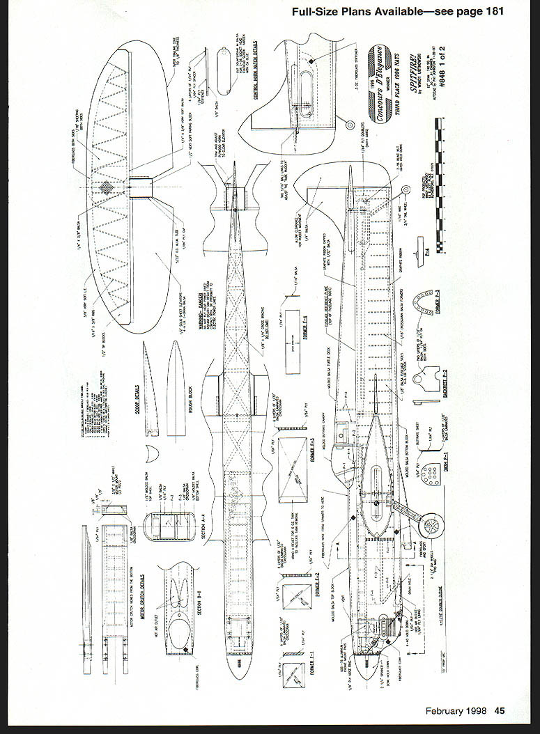
Spitfire
Windy Urtnowski & Joe Adamusko
Joe Adamusko and I have shared a love of Spitfires for many years. In the spring of 1995 we committed to what was ultimately "The Spitfire Project." Little did we realize just how all-consuming the project would become, or how many people would contribute significantly to the final outcome.
Bob Martens created one of the finest sets of drawings for a CL Stunter, working from actual parts and templates used to construct the original two Spitfire models. Ed Gallagher was instrumental in the composite material work; expert machining of the spinner male molds and backplates was by Ron Kieffer; anodizing was done by George Venturini; and vacuum-forming of the canopies was done by Dave Midgley.
As the design evolved, Joe and I went back and forth nearly endlessly. We drew so many plans that the postman commented on the increase in mail that spring. Joe massaged my drawings, I made changes to his, and eventually we arrived at the design you see here. It didn't come easily, cheaply, or quickly, but the result matched what we envisioned from the start.
The airfoil is pure Patternmaster—Big Jim Greenaway, the Patternmaster designer, has a gift for fine wing design. His help and feedback were instrumental in finalizing many aspects of the Spitfire's areas and force arrangements.
We wanted dead-reliable motor runs with a WWII fighter sound, so we chose Big Jim Super Tigre .60 "hemi."
We decided the project should incorporate features seldom seen in the world of "pro Stunt," including:
- Molded leading-edge sheeting
- Aft top deck, bottom block, and nose block shaped from balsa molded over solid carved plugs
- Geodetic horizontal stabilizer construction
- Handmade fiberglass spinners and cowlings
- Five-bladed carbon-fiber/epoxy composite props
- Composite molded (nonfunctional) exhaust stacks and landing-gear details
CONSTRUCTION
Wing
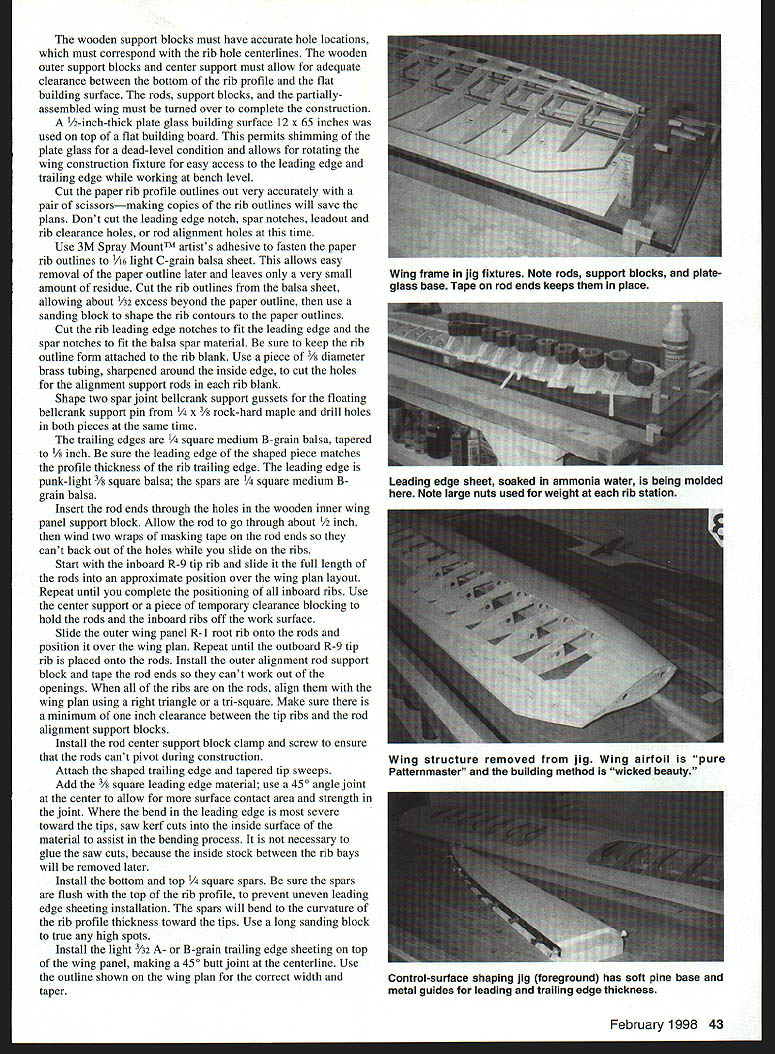
One reason Spitfires haven't been modeled often is the wing can be a complex build. Using the method Joe devised, it isn't really very difficult, and the results are what Joe calls "wicked beauty"—a straight, rigid, warp-free wing, a prerequisite for a Stunt model. We used the proven rib-alignment rod and support-block method, which also lends itself to molding balsa leading-edge sheeting.
Important materials and dimensions (typical):
- Rods: type 303 stainless steel, 3/16" dia. × 60" length (obtain random lengths from an industrial supplier)
- Rod end support blocks & center support: 3/4" soft pine; end support blocks 3 × 7"
- Holes in support blocks: 3/16" drilled on centerline, spaced 2-1/4" apart
- Building surface: 1/2"-thick plate glass, 12 × 65" (placed on a flat building board for shimming)
- Ribs: cut from 1/8" light C-grain balsa (fasten paper outlines with 3M Spray Mount)
- Trailing edge: 1/4" square medium B-grain balsa, tapered to 1/8"
- Leading edge stock: punk-light 3/8" square balsa
- Spars: 1/4" square medium B-grain balsa
- Spar joint & bellcrank gussets: rock-hard maple as specified
Step-by-step highlights:
- Prepare building surface and support blocks; drill holes accurately so they correspond to rib hole centerlines. Allow clearance between bottom rib profile and building surface.
- Make accurate paper rib-profile outlines; do not cut leading-edge notches, spar notches, leadout holes, or rod-alignment holes yet. Use 3M Spray Mount to adhere paper to 1/8" balsa and cut rib blanks.
- Transfer rib numbers and hole locations from plans to each rib. Use a sharpened piece of 3/32" brass tubing to cut the alignment-rod holes in each rib blank.
- Assemble rods and support blocks on the jig. Insert rods through the center support block (about 1/2" through) and secure with two wraps of masking tape so rods won't back out while sliding on ribs.
- Slide ribs onto the rods in order (start with inboard R-9 tip rib), square each rib to the centerline, and align using a right triangle or tri-square. Maintain at least 1" clearance between tip ribs and rod-end support blocks.
- Install the trailing edge and tapered tip sweeps. Add 3/8" square leading-edge material with a 45° angle joint at the center; saw kerf the inside surface where severe bends occur.
- Install bottom and top 1/4" square spars, flush with the top of the rib profile to ensure even leading-edge sheeting installation. Use a long sanding block to true any high spots.
- Install light 3/32" trailing-edge sheeting on top of the panel, making a 45° butt joint at the centerline. Pay special attention to the tip-sweep area where sheeting is laminated: soak the sheeting with ammonia water to induce preset bends, and use small C-clamps and shims to hold laminates tight.
- Install a center wing sheeting strip (about 2½" wide) against the trailing-edge sheeting to avoid interference with the center alignment block when turning the wing.
- Mold the leading-edge sheeting by using the wing structure as a forming buck:
- Make reverse-curve hold-down blocks (1" thick balsa plank cut to rib contours).
- Cut 3/32" A-grain light balsa leading-edge sheeting to plan outline; only mold one piece at a time.
- Soak both sides of the sheeting with ammonia water until fibers expand (yellowish color), hand-shape, then place over the wing and clamp with weighted hold-down blocks from center outward. Dry ~1½ hours.
- Remove excess stock between rib bays after molding to save weight and leave radiused intersections.
- Glue one molded leading-edge panel at a time. Preglue rib contact and spar contact areas with a thin layer of cement and allow to dry—this yields the best bonded joint. Use Ambroid glue for its working time when applying sheeting; hold sheeting with masking tape wrapped partially around the spar rather than pins.
- If a sheeting area doesn't make full contact, use weighted molding blocks as clamps (beware of too much weight causing warp).
- Leave the center sheeting for final installation until the top-spar joiner gusset, bellcrank, pushrod, and leadout wires are installed. Turn the wing over carefully to complete the bottom: install trailing edge, leading edge, and tip sheeting. Cut clearance notches in ribs behind the spar center joint to accept the hardwood spar joint bellcrank support gusset; epoxy the gusset in place.
- Remove the alignment rods slowly. Protect the wing sheeting with a soft pad under the wing; remove tape from rod ends and center support block; straighten rods and scrape off any glue before withdrawing them. Trim alignment rod support tabs from ribs and reglue bottom sheeting joints as needed.
- Finish-sand sheeting joints and shape the leading-edge radius. Install landing-gear blocks, wing tips, leadout guide, tip weight box, rib capstrips, controls, and hinge blocks. Final fillets and fairings are sanded to blend surfaces.
Notes:
- The base wing core (with hardwood spar joint gussets and bellcrank) should weigh about eight ounces at this stage.
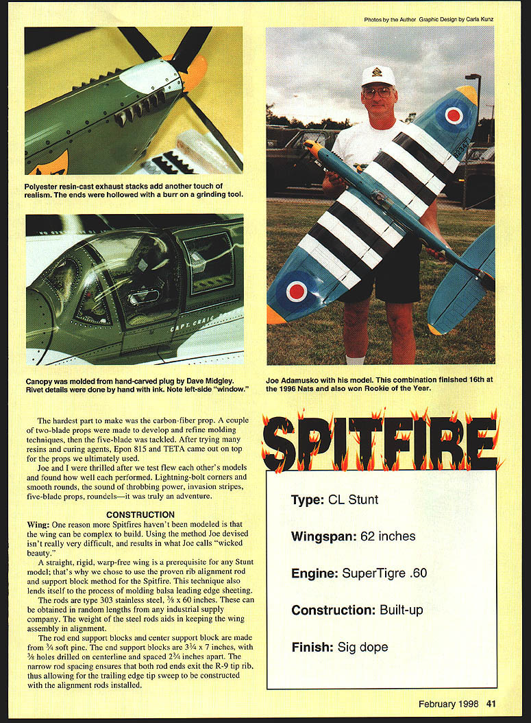
- Polyester resin–cast exhaust stacks add realism; hollow the ends with a burr grinding tool. Canopy molded from a hand-carved plug by Dave Midgley. Rivet details done by hand with ink.
- The carbon-fiber five-blade prop was the most difficult item to produce. After trials, Epon 815 resin and TETA curing agent proved best for the props.
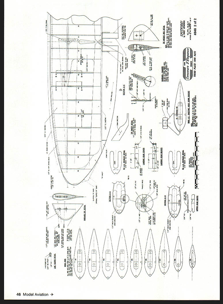
Stabilizer
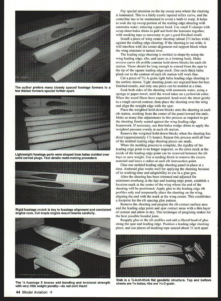
The stabilizer uses geodetic construction for lightness and rigidity.
Materials & preparation:
- Two pieces of 4"-wide light C-grain sheeting (approximately stab span length)
- Trailing-edge spar: punk-light 1/4" × 3/8"
- Ribs: 24 blanks, 1/16" × 3/8" C-grain
- Leading edge: punk-light 3/8" balsa (saw kerf halfway through the inside face)
Steps:
- Square one long edge of the bottom sheeting as the trailing edge; cut the leading-edge curve to shape.
- Mark geodetic rib locations on the bottom sheeting and pin the sheeting over waxed paper on a flat building board.
- Glue the trailing-edge spar in place, install the kerfed leading edge (soak and bend with ammonia water), and glue ribs on the layout lines working from center outward. Add a scrap trailing-edge doubler at the control-horn center.
- When set, remove pins, true with a sanding block, then attach top sheeting with minimal slow-setting epoxy, weighting until cured.
- Shape flaps/elevators using sanding jigs (soft pine base and light-gage sheet-metal thickness guides). Cut control surfaces from 4–6 lb. C-grain balsa with grain aligned for curvature; sand progressively from coarse (60–80 grit) to fine (220 grit) using the guides for accurate taper.
Fuselage
The fuselage follows a Big Jim type of construction—very rigid and vibration-resistant. No blocks need carving; shells and canopy are available, and the removable cowl is molded fiberglass (strong and lighter than wood).
Key features:
- Very light: complete fuselage weighs about 10 ounces
- Engine-mount crutch: an enclosed box with 1/64" plywood sandwiching maple mount beams and spanwise balsa spacers. Use a matched pair of maple beams and orient grain so mounting-bolt clamping compresses grain for secure mounting.
- Doublers: 1/16" plywood (do not skimp)
- Nose reinforcement: lightweight fiberglass cloth over the nose area to just aft of the wing leading edge
- Taper plywood doublers inside sides aft of wing cutout to about 3/32" thickness at the tailpost to save weight; blend edges to avoid stress risers
- Add carbon "tow" along top and bottom edges of fuselage sides for strength with negligible weight penalty
- Use many closely spaced formers to achieve a straight, strong fuselage and to allow fair sanding without an odd appearance
Assembly and alignment:
- Position the engine-mount crutch inverted over the fuselage plan and tack-glue the fuselage sides to it. Use a triangle to ensure sides are perpendicular to the building surface.
- Build the fuselage top-down on a flat table and block it so the wing reference line is 0° parallel to the table. Use wing-section centerlines drawn on the fuselage sides forward and aft of the cutout as references and spot-glue or pin the sides to the table to make the table a large reference plane. This ensures wing centerline, horizontal centerline, and engine thrustline are all at 0° to each other.
- Make wing cutout cuts at an angle (front-to-rear and top-to-bottom). This avoids future cracking that can occur with "square" cuts.
- Fit the wing temporarily, checking lateral centering and that leading-edge and trailing-edge reference marks align with fuselage reference lines. Make small adjustments for perfect alignment.
- When satisfied, glue the wing in with slow-curing epoxy, checking alignment continuously while it sets.
- Refit the cutout fuselage bottom pieces under the wing, trimming as needed so bottom edges align with fuselage bottoms. Add plywood and balsa doublers below the wing. Let cure (overnight recommended).
- Install the horizontal stabilizer: set the flaps and elevators at 0°, center the stabilizer on the fuselage centerline, then check that the distance from the flap hinge line to the elevator hinge line is the same on both sides. Ideally, these two measurements will be 18"; if equal and within ~1/16" of 18", elevator neutral can be adjusted by reordering the pushrod wire. Glue the stabilizer with slow-curing epoxy, ensuring it is flat with the wing and that hinge lines are parallel.
- Install 1/8" fuselage X-braces aft of the wing for bending and torsional strength. Fit braces carefully to avoid building in twist.
- Glue the nose block on with epoxy for strength and fuel resistance. Glue turtledeck and bottom blocks with thin CA (relieve the turtledeck to clear the horizontal stabilizer).
- Align and glue the long bottom block working from front to rear; use the cowl temporarily to check bottom-block fit. After all blocks are glued in, run thin CA inside along seams between sides and blocks.
- Install the vertical stabilizer with slow-curing epoxy, ensuring it is on the fuselage centerline and perpendicular to the horizontal stabilizer. Check alignment until epoxy is rock-solid.
Finish fittings:
- Install control hardware, bellcrank, pushrods, servos, landing-gear mounts, and any fillets or fairings required.
- Final sanding and fairing blend all surfaces for finishing.
Finishing and Detailing
Selecting paint schemes was one of the most enjoyable parts—Spitfires have been painted in almost every camouflage scheme imaginable. We used a genuine WWII Spitfire color chart and had acrylic lacquer pigments custom-mixed. Adding these pigments to Sig Lite Coat clear dope gave us low-shrink dope colors suitable for traditional Concours finishing.
Details:
- Polyester resin–cast exhaust stacks for realism (hollow ends with a burr tool)
- Canopy molded by Dave Midgley from a hand-carved plug
- Rivet details applied by hand with ink
- Simulated wing-mounted radiators are best used for static judging only; they tended to soften outside corners during flight, so we do not use them for competition flying
Trial by Fire
The Spitfires debuted at the 1996 Nats. At appearance judging I was in the front row alone, Joe was in the second row alone, and pilots voted the Spit the Concours winner. Joe finished 16th overall in Expert; I got third. Joe was also PAMPA's 1996 Rookie of the Year.
Developing a scale-like model requires getting compromises right—you want the "look," but precision Stunt performance must be there, too. All the early effort during design paid off: this is the best model either of us has ever flown.
Stunt News is a newsletter you should get if you have any interest in CL Stunt. Join PAMPA by sending $20 to: PAMPA 158 Flying Cloud Isle Foster City CA 94404
Specifications
- Type: CL Stunt
- Wingspan: 62 inches
- Engine: SuperTigre .60 (SuperTigre 60)
- Construction: Built-up
- Finish: Sig dope
Notes
- The carbon-fiber five-blade prop development required trial runs with two-blade props first; Epon 815 resin with TETA curing agent proved best.
- The molded leading-edge sheeting technique is critical to avoid built-in warp—maintain centerline during lamination and use ammonia soak to preset bends where needed.
Contacts
Windy Urtnowski 93 Elliot Pl. Rutherford, NJ 07070
Joe Adamusko 211 Hidden Valley Ln. Newtown, PA 18940
Transcribed from original scans by AI. Minor OCR errors may remain.

