
Spoilers and Air Brakes for Sailplanes
Ken Cashion
A couple of decades ago Frank Zaic gave me such good advice about spoilers that I put it on a placard for my model shop: "Don't go too high if you want to come down in a hurry."
Getting models back down is easy but it is disconcerting to maintain visual contact by the sun reflecting from fluttering wings. Yes, getting them down is easy; but to do it without stress is sometimes difficult.
Spoilers and air brakes permit models to come down in a hurry—safely. Just as significant, they allow us to cruise way up there, just below "frantic" altitude.
Adding spoilers to a model during construction isn't difficult, but what about an already-built model—the real good one that you almost lost last Sunday?
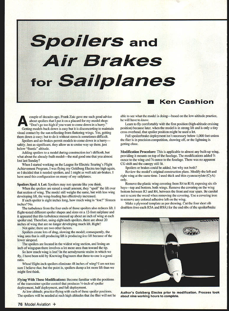
When I started working on the League for Electric Soaring's Flight Achievement Program, I was flying my Goldberg Electra too high again, so I decided it needed spoilers, and I might as well add air brakes. I have used this configuration on many of my sailplanes.
Spoilers Spoil A Lot
Spoilers may not operate like you think.
When the spoilers are raised a small amount, they "spoil" the lift over that section of wing. The model still weighs the same, but with less wing developing lift, the effective wing loading increases.
If each spoiler is eight inches long, how much wing is "lost"? Sixteen inches? No.
The turbulence from the four ends of those spoilers also reduces lift. I flight-tested different spoiler shapes and sizes on a 12-foot sailplane and it appeared that this turbulence messed up about an inch of wing at each spoiler end. Therefore, using eight-inch spoilers, there are about 20 inches of wing that are no longer developing much lift. Right?
Not quite; there are two other factors.
- Spoilers create lots of drag, slowing the model; consequently, the wing area that is still producing lift is producing less lift because of the lower airspeed.
- The spoilers are located in the widest wing section, and losing an inch of wingspan there involves a lot more area than toward the tip.
So how much wing is lost? In the aerodynamic realm in which we fly, I have been told by knowledgeable engineers that a three-to-one ratio is a good rule of thumb.
Whoa! Eight-inch spoilers eliminate 48 inches of wing? I am not too sure I believe that, but the point is spoilers dump a lot more lift than we might first think.
Flying With These Modifications
Become familiar with the transmitter spoiler control positions that produce 1/4-inch of spoiler deployment, half deployment, and full deployment.
At low altitude, practice flying with each of these spoiler positions. The spoilers will be needed at such high altitudes that the flier will not be able to see what the model is doing—based on the low-altitude practice, he will have to know.
Learn to fly comfortably with the first position (high-altitude cruising position) because later, when the model is in strong lift and is only a tiny cross overhead, that spoiler position might be used a lot.
Full spoiler/brake deployment isn't necessary below 1,000 feet unless the flier is in precision competition, showing off, or the lightning is getting close.
Modification Procedure
Applicable to almost any built-up wing that mounts on top of the fuselage. The modifications added about 3/4 ounce to the wing and 3/4 ounce to the fuselage. There was no apparent CG shift and the canopy still fit.
Spoilers or brakes could be added, but why not both?
Review the model's original construction plans. Modify the left and right wing at the same time. I used thick and thin cyanoacrylate (CyA) only.
- Remove the plastic wing covering from R4 to R10, exposing six rib bays—top and bottom, both wings. Remove the covering on the wing bottom between R3 and R4, between the front and rear spars. Be careful not to score the wood when removing the covering. Use a covering iron to remove any colored adhesive left on the wing.
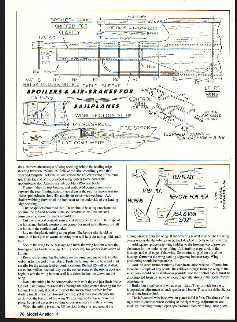
- Make a plywood template as per the plans. Cut the four short rib doublers (two each R5A and R9A) for the end ribs of the spoiler/brake.
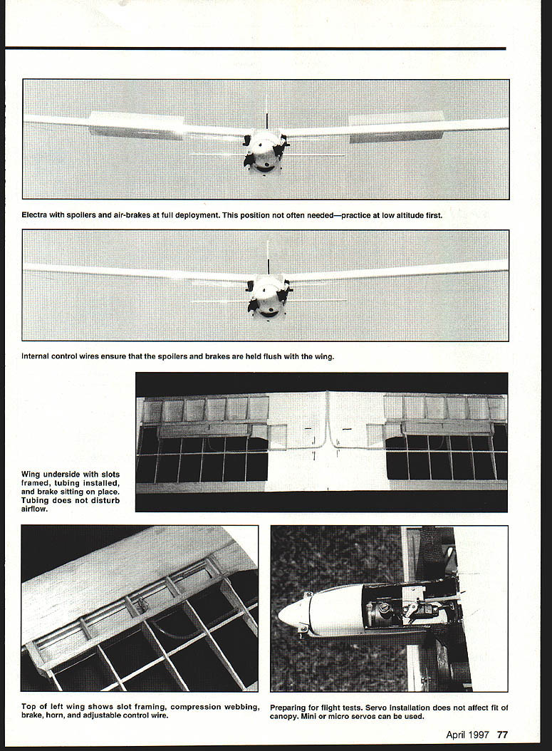
- Frame in the slot top, bottom, and ends. Add compression webs between the rear framing strips; place them at the rear for maximum area inside the spoiler/brake slots. (Do not distort strips with webbing.) Add similar webbing forward of the front spar to the underside of the leading edge sheeting.
- Cut the spoilers/brakes to size. There should be adequate clearance because the top and bottom of the spoilers/brakes will be covered; consequently, allow for material buildup.
- Cut the plywood control horns and drill for control wire. The shape of the horns and the hole positions are correct for most servo throws. Install the horns in the spoilers and brakes.
- Lay out the plastic tubing as per the plans. The bend radii should be smooth. A heat gun or warm soldering iron will help the tubing hold small radii.
- Secure the wing to the fuselage and mark the wing bottom where the fuselage edges touch the wing. This is necessary for proper installation of tubing.
- Remove the wing, lay the tubing on the wing, and make holes in the webbing for the end of the tubing. Push the tubing into the hole and mark the ribs for the tubing feed-through locations. R6 and R5 will be drilled; the others will be notched. Lay out the easiest route so the tubing does not begin to exit the wing bottom until it is 1/8-inch inside the line drawn on the wing.
- Install the tubing in the compression web with the end just flush inside the slot. Cut minimum-sized slots through the wing center sheeting for the tubing. The tubing should be clear of the under-wing surface before starting much of the turn toward the nose, yet it must not interrupt the airflow on the bottom of the wing. The tubing can be thick-CyAed in place, but avoid excessive cutting across-grain into the sheeting.
- When the tubing is secure, fill the slots in the ribs and around the tubing where it exits the wing. If the covering is well attached to the wing center underside, the tubing can be thick-CyAed directly to the covering.
- Add square spruce strip wing saddles to the fuselage top to provide clearance for the under-wing tubing. Add trailing-edge stock to the fuselage at the aft edge of the wing. Some trimming of the top of the fuselage former at the wing leading edge may be necessary. Wing positioning should be repeatable.
- Add the servo (mini or micro). Key points:
- The cable exit angle from the wing to the servo arm should be as shallow as possible.
- The control cables must be disconnectable from the servo without major alterations in the spoiler/brake adjustments.
- Build four small control wires as per the plans. They provide for easy, independent adjustment of each spoiler and brake. This is not difficult, nor are the components critical.
- Build the left control wire first (shown on the plans). The shape of the right wire is obvious when looking at the right wing.
- Adjustments are made by reaching through open spoiler/brake slots with long-nose pliers.
- This wire shape helps prevent overloading the servo at extreme ends of servo throw and holds spoilers/brakes closed under spring compression.
- Solder the control wires to the control cable, cut the cable slightly overlength, and solder the end of the cut cable to prevent fraying (clean off flux).
- Install the cables through the slots and temporarily attach the spoilers/brakes to their respective control wires. Slight bending of the control wires will let the spoiler/brake surfaces sit flush. Almost any tape can be used as a temporary hinge.
- Check spoiler throw, select the most appropriate horn hole, and connect the cable to the servo arm. A short piece of tubing over the cables will prevent excessive cable flexing. A small collar can be used between the servo control horn and the wing to clamp the cables together after everything has been adjusted. For many reasons, greater servo throw is needed than the distance the control horns must travel. This is no problem and reduces the criticality of all dimensions.
- Adjust the control wires and the attachment to the servo until all operate properly and the wing can be removed and reinstalled easily. Do not proceed until all this can be done.
- When everything is operating properly, the wing, spoilers, and brakes can be covered. It may be necessary to retrim the seating position of the spoilers/brakes against the ribs because of the added covering thickness—use emery boards. Doping (sealing) exposed balsa and plywood horns is a good idea at this time.
- Add 1/32-inch balsa (or tape) to close all open rib bays without restricting the movement of the control wires and horns. Add the hinges (I used TrimKote). Thin cardboard shims can be used at the ends and the trailing edge of the spoiler/brake slots so the hinges can be properly positioned.
Total work time was nine hours, three minutes.
If you have questions about the conversion, or about the League for Electric Soaring, please write to me:
Ken Cashion 157 Tennyson Cove Picayune, MS 39466
Transcribed from original scans by AI. Minor OCR errors may remain.

