

SPORT SPEED CONTROL
Bob Kopski
Part One of the "Sport Speed Control" was presented in the September 1999 issue.
POWER PLATE ASSEMBLY
Assembly of the Power Plate begins by accurately fabricating the aluminum heat sink. Use the full-size patterns in the Power Plate Assembly drawing to aid in the steps that follow.
It's easier to saw 3/32" aluminum if you first double-stick tape it to a scrap of 1/8" Lite Ply as a backing. Mark and drill the five 1/8" holes, deburr all holes and edges, and radius the four corners slightly. Caution: it is very important that the component side of the aluminum plate is fully deburred and smooth before mounting any parts. Be sure the aluminum stays flat, and confirm that the finished piece matches the full-size drawing.
Cut the PC board to size. This simple PC board can be etched or lines can be scored with a #11 knife and the copper tracks peeled back. Be sure that the result closely matches the full-size drawing.
Attach the PC board to the heat sink using a small amount of rubber-based contact cement. Be sure it is correctly positioned; proper fit of the remaining components depends on this. I use two temporary tape tracks on the heat sink so the PC board can drop in between. Polish the copper and clean this subassembly with solvent.
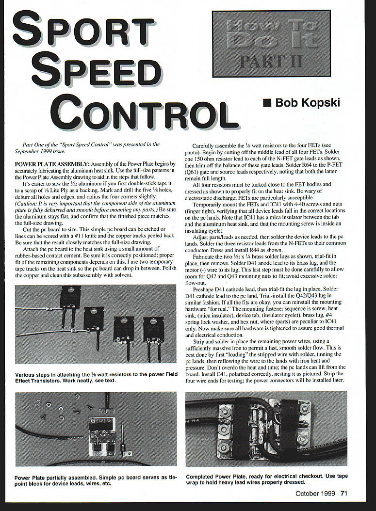
Carefully assemble the 1/8-watt resistors to the four FETs (see photo). Begin by cutting off the middle lead of all four FETs. Solder one 150-ohm resistor lead to each of the N-FET gate leads as shown, then trim off the balance of these gate leads. Solder R64 to the P-FET (Q61) gate and source leads respectively, noting that both the latter remain full length.
All four resistors must be tucked close to the FET bodies and dressed as shown to properly fit on the heat sink. Be wary of electrostatic discharge; FETs are particularly susceptible.
Temporarily mount the FETs and IC41 with 4-40 screws and nuts (finger tight), verifying that all device leads fall in the correct locations on the PC lands. Note that IC41 has a mica insulator between the tab and the aluminum heat sink, and that the mounting screw is in an insulating eyelet.
Adjust parts/leads as needed, then solder the device leads to the PC lands. Solder the three resistor leads from the N-FETs to their common conductor. Dress and install R44 as shown.
Fabricate the two 1/32" x 1/4" brass solder lugs as shown, trial-fit in place, then remove. Solder D41 anode lead to its brass lug and the motor (-) wire to its lug. This last step must be done carefully to allow room for Q42 and Q43 mounting nuts; avoid excessive solder flow-out.
Preshape D41 cathode lead, then trial-fit the lug in place. Solder D41 cathode lead to the PC land. Trial-install the Q42/Q43 lug in similar fashion. If all the fits are okay, you can reinstall the mounting hardware "for real." The mounting fastener sequence is: screw, heat sink, (mica insulator), device tab, (insulator eyelet), brass lug, #4 spring lock washer, and hex nut — where parenthetical parts are peculiar to IC41 only. Now make sure all hardware is tightened to assure good thermal and electrical conduction.
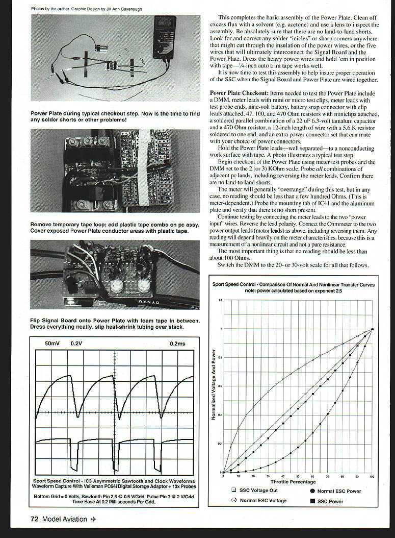
Strip and solder in place the remaining power wires, using a sufficiently massive iron to permit a fast, smooth solder flow. This is best done by first "loading" the stripped wire with solder, tinning the PC lands, then reflowing the wire to the lands with iron heat and pressure. Don't overdo the heat and time; the PC lands can lift from the board. Install C41, polarized correctly, nesting it as pictured. Strip the four wire ends for testing; the power connectors will be installed later.
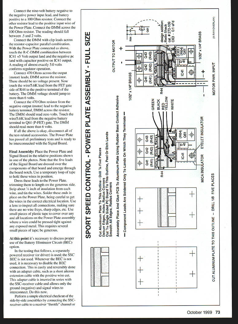
This completes the basic assembly of the Power Plate. Clean off excess flux with a solvent (e.g., acetone) and use a lens to inspect the assembly. Be absolutely sure that there are no land-to-land shorts. Look for and correct any solder "icicles" or sharp corners anywhere that might cut through the insulation of the power wires, or the five wires that will ultimately interconnect the Signal Board and the Power Plate. Dress the heavy power wires and hold them in position with tape — 1/4-inch auto trim tape works well.
It is now time to test this assembly to help insure proper operation of the SSC when the Signal Board and Power Plate are wired together.
POWER PLATE CHECKOUT
Items needed to test the Power Plate:
- DMM (digital multimeter)
- Meter leads with mini or micro test clips
- Meter leads with test probe ends
- Nine-volt battery and battery snap connector with clip leads attached
- 47, 100, and 470 ohm resistors with miniclips attached
- A soldered parallel combination of a 22 µF 6.3-volt tantalum capacitor and a 470 ohm resistor
- A 12-inch length of wire with a 5.6 KΩ resistor soldered to one end
- An extra power connector set that can mate with your choice of power connectors
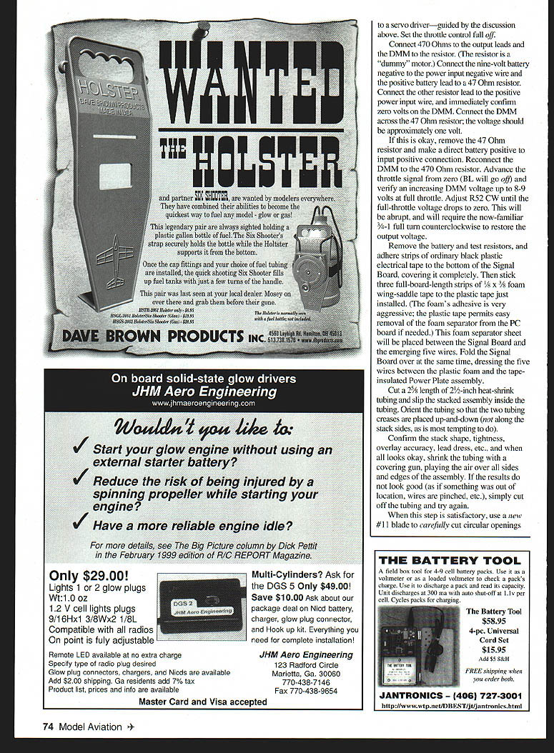
Hold the Power Plate leads — well separated — to a nonconducting work surface with tape.
Begin checkout of the Power Plate using meter test probes and the DMM set to the 2 (or 3) KΩ scale. Probe all combinations of adjacent PC lands, including reversing the meter leads. Confirm there are no land-to-land shorts.
The meter will generally "overrange" during this test, but in any case no reading should be less than a few hundred ohms (this is meter-dependent). Probe the mounting tab of IC41 and the aluminum plate and verify that there is no short present.
Continue testing by connecting the meter leads to the two "power input" wires. Reverse the lead polarity. Connect the ohmmeter to the two power output leads (motor leads) as above, including reversing them. Any reading will depend heavily on the meter characteristics, because this is a measurement of a nonlinear circuit and not a pure resistance. The most important thing is that no reading should be less than about 100 ohms.
Switch the DMM to the 20- or 30-volt scale for all that follows.
- Connect the nine-volt battery negative to the negative power input lead, and battery positive to a 100-ohm resistor. Connect the other resistor lead to the positive input wire of the Power Plate. Connect the DMM across the 100-ohm resistor. The reading should fall between 0.5 and 2 volts.
- Connect the DMM with clip leads across the resistor-capacitor parallel combination. With the Power Plate connected as above, touch the R-C-DMM combination between IC41 +5 Volt output land and the negative PC land with the capacitor positive on IC41 output. A reading of almost exactly 5.0 volts confirms regulator operation.
- Connect 470 ohms across the output (motor) leads; DMM across the resistor. There should be no voltage present. Now touch the wire/5.6K lead from the FET gate side of R44 to the positive terminal of the battery. The DMM voltage should jump to more than 6 volts.
- Connect the 470 ohm resistor from the negative output (motor) lead to the negative battery terminal, DMM across the resistor. The DMM should read zero volts. Touch the wire/5.6K lead from the negative battery terminal to Q61 (P-FET) gate. The DMM should read more than 6 volts.
If all the above is okay, disconnect all of the test-related accessories. The Power Plate has passed all preliminary tests and is ready to be interconnected with the Signal Board.
FINAL ASSEMBLY
Place the Power Plate and Signal Board in the relative positions shown in one of the photos. Note that the five leads of the Signal Board are routed over the components of that board and emerge through the board notch. Use a temporary loop of tape to hold these wires in position.
Dress these leads to the Power Plate, trimming them to length on the generous side. Strip about 1/8 inch of insulation from each wire, and tin the wires. Solder these ends in place on the Power Plate, being careful to get the wires in the correct electrical locations. Use a lens to inspect all connections, making sure there are no wire frays or sharp edges. Use small pieces of plastic tape to cover over any and all locations on the Power Plate assembly where a wire could be pressed tight against any exposed metal. Be generous with the tape.
At this point it's necessary to discuss proper use of the Battery Eliminator Circuit (BEC) option.
In the testing that follows, a separately powered receiver (or driver) is used; the SSC BEC is not used. Whenever the BEC is not used, it is necessary to disable the BEC connection. This is easily and reversibly done with an adapter cable, such as a short aileron extension cable with the positive wire cut. This adapter cable is inserted in series with the SSC–receiver cable and allows only the ground (negative) and signal wires to interconnect. Do this now.
Perform a simple electrical checkout of the side-by-side assemblies by connecting the SSC–receiver cable to a receiver "throttle" channel or to a servo driver — guided by the discussion above. Set the throttle control full off.
Connect 470 ohms to the output leads and the DMM to the resistor (the resistor is a "dummy" motor). Connect the nine-volt battery negative to the power input negative wire and the positive battery lead to a 47 ohm resistor. Connect the other resistor lead to the positive power input wire, and immediately confirm zero volts on the DMM. Connect the DMM across the 47 ohm resistor; the voltage should be approximately one volt.
If this is okay, remove the 47 ohm resistor and make a direct battery positive-to-input positive connection. Reconnect the DMM to the 470 ohm resistor. Advance the throttle signal from zero (BL will go off) and verify an increasing DMM voltage up to 8.9 volts at full throttle. Adjust R52 clockwise until the full-throttle voltage drops to zero. This will be abrupt, and will require the now-familiar 3/8–1/2 turn counterclockwise to restore the output voltage.
Remove the battery and test resistors, and adhere strips of ordinary black plastic electrical tape to the bottom of the Signal Board, covering it completely. Then stick three full-board-length strips of 1/8" x 3/8" foam wing-saddle tape to the plastic tape just installed. (The foam’s adhesive is very aggressive; the plastic tape permits easy removal of the foam separator from the PC board if needed.) This foam separator sheet will be placed between the Signal Board and the emerging five wires. Fold the Signal Board over at the same time, dressing the five wires between the plastic foam and the tape-insulated Power Plate assembly.
Cut a 2-1/2" length of heat-shrink tubing and slip the stacked assembly inside the tubing. Orient the tubing so that the two tubing creases are placed up-and-down (not along the stack sides). Confirm the stack shape, tightness, overlay accuracy, lead dress, etc., and when all looks okay, shrink the tubing with a covering gun, playing the air over all sides and edges of the assembly. If the results do not look good (as if something was out of location, wires are pinched, etc.), simply cut off the tubing and try again.
When this step is satisfactory, use a new #11 blade to carefully cut circular openings in the tubing for the five wires and over the three trimmer resistors to allow adjustment of these parts. Install the power connectors of choice on the power input and motor output leads.
Your Sport Speed Control is ready for final checkout and adjustment.
FINAL CONTROL CHECKOUT
Decide on the number of cells you will use. Connect the nine-volt battery to the power input connectors, using the battery leads and extra mating power connector. Be sure the polarity is correct.
Measure the voltage on the battery terminals = Vbatt. Use this value to calculate: Vp2b = (2.5 × Vbatt) / (0.9 × number of cells).
Connect the DMM negative to TIP and the positive to TP2B (the test points are still accessible through the end of the shrink tubing). Adjust R52 to read the value just calculated, and disconnect the battery and meter.
Note: If your intended cell count is six or seven, change the "0.9" in the equation to "0.95". This allows margin for tolerance stackup.
This adjustment, which can be redone any time you change cell count, calibrates the cutoff circuit to shut the motor down at a pack voltage equal to 0.9 × number of cells (or 0.95 × number of cells if adjusted as noted). In effect, this sets cutoff at 0.9 volts per cell nominal.
Note that any pack of fewer cells would not allow the SSC to run, or run for very long. A pack of more cells would experience a "deeper" discharge than need be. If you are not using BEC and do not wish to use battery cutoff protection, or if you simply need an expedient, turn R52 fully counterclockwise.
For those with access to a variable power supply, the calibration can be done directly by setting the supply to 0.9 × number of cells (or 0.95 × number of cells) and connecting that to the power input wires. Adjust R52 as above. You can even verify operation with the DMM on the 470 ohm resistor on the output leads; the output will drop off abruptly when the power supply is lowered through the adjusted cutoff value.
You can now do a verification bench run of your power system or just "cold turkey" install the SSC in your airplane.
Always use an arming switch between the battery and the SSC. If you use BEC, do not install a fuse in the SSC power input line; rather, install a fuse in one motor lead. If you do not use BEC, install the fuse in the battery–fuse–arming-switch manner. Note that if you use BEC, the receiver is powered by the arming switch as well.
I use double-stick Velcro™ (Radio Shack 64-2345) to mount the SSC. I suggest you arrange the SSC to have the trim pots accessible and the "brake lite" visible from the installation position in your airplane. You may want to touch up the adjustments beyond what you did during the test and checkout of the SSC.
Now go proudly fly an electric with a speed control that you built from scratch! Remember, this nonlinear speed control will have a "feel" different from any other control you're likely to have used; you may want to trash all those others!
Here's hoping you enjoy your Sport Speed Control as I do. And, if you have any questions or comments, please do write me directly.
A circuit design improvement has been added to the SSC since this article was written. This necessary modification uses one additional part not previously shown in the parts list. It is Radio Shack catalog #272-109, a tiny 0.1 uF monolithic capacitor, connected between the gate and source leads of Q61 similar to resistor R64 already shown. Bend the capacitor leads outward, trim them to about 1/8" long, and solder them on the top of the FET leads as the last part to be built in place prior to installing the power wires. Be sure to dress the capacitor body so its ends do not project higher than the 0.64" FET body itself, and make sure nothing is touching the cutoff middle (drain) FET lead. No other aspect of this article is affected.
I wish to thank my good friends and fellow E-modelers Hal Phan and Bill Smith, who have built, flown, and offered constructive comment on the Sport Speed Control. Their early interest and easy success allow me to offer this article with a high confidence in its "buildability" and functionality.
Bob Kopski 25 West End Dr. Lansdale, PA 19446
Transcribed from original scans by AI. Minor OCR errors may remain.

