
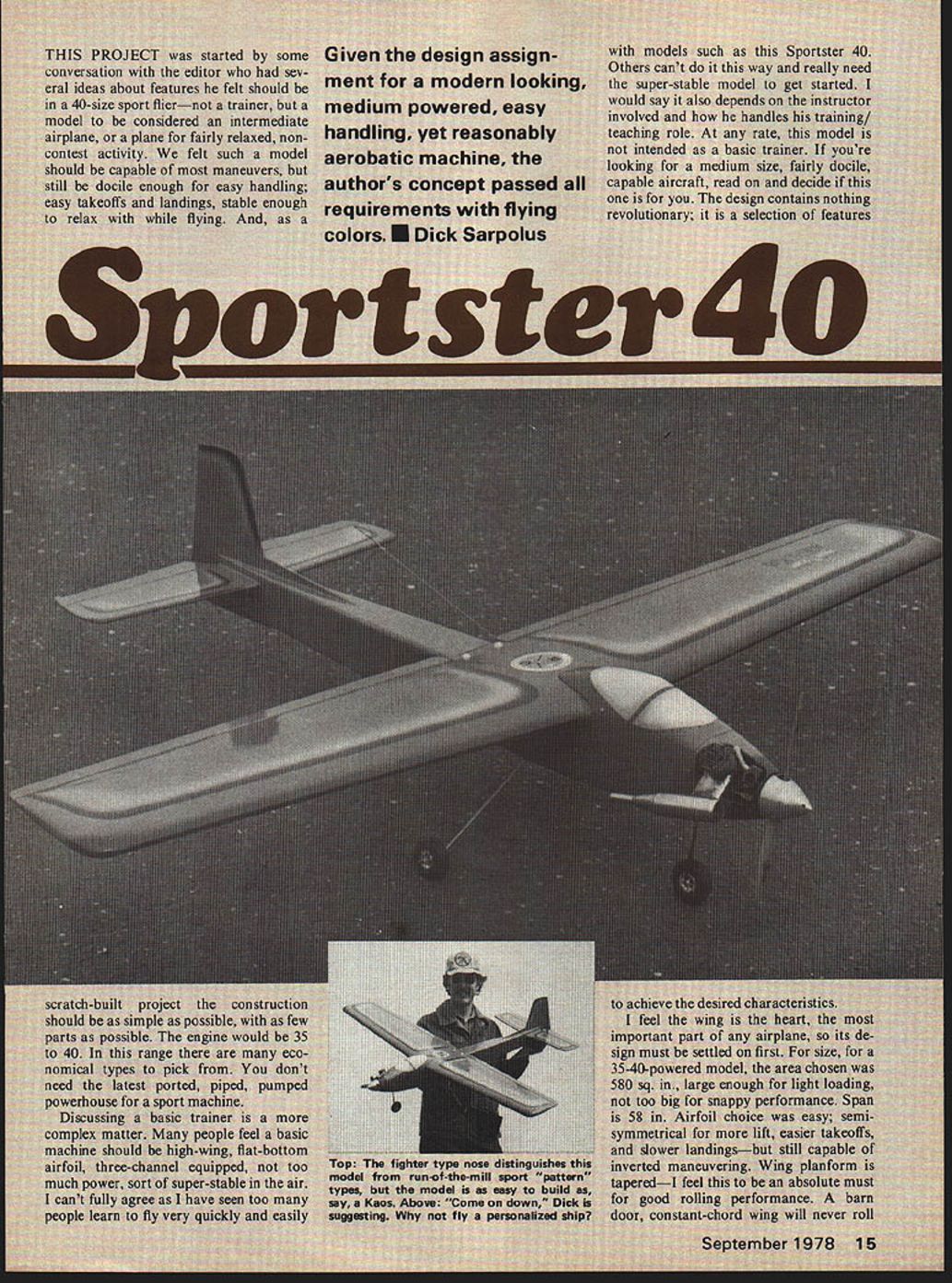
Sportster 40
THIS PROJECT was started by some conversation with the editor who had several ideas about features he felt should be in a 40-size sport flier — not a trainer, but a model to be considered an intermediate airplane, or a plane for fairly relaxed, non-contest activity. We felt such a model should be capable of most maneuvers, but still be docile enough for easy handling; easy takeoffs and landings, stable enough to relax with while flying. And, as a scratch-built project the construction should be as simple as possible, with as few parts as possible. The engine would be 35 to 40. In this range there are many economical types to pick from. You don't need the latest ported, piped, pumped powerhouse for a sport machine.
Discussing a basic trainer is a more complex matter. Many people feel a basic machine should be high-wing, flat-bottom airfoil, three-channel equipped, not too much power, sort of super-stable in the air. I can't fully agree as I have seen too many people learn to fly very quickly and easily with models such as this Sportster 40. Others can't do it this way and really need the super-stable model to get started. I would say it also depends on the instructor involved and how he handles his training/teaching role. At any rate, this model is not intended as a basic trainer. If you're looking for a medium size, fairly docile, capable aircraft, read on and decide if this one is for you. The design contains nothing revolutionary; it is a selection of features to achieve the desired characteristics.
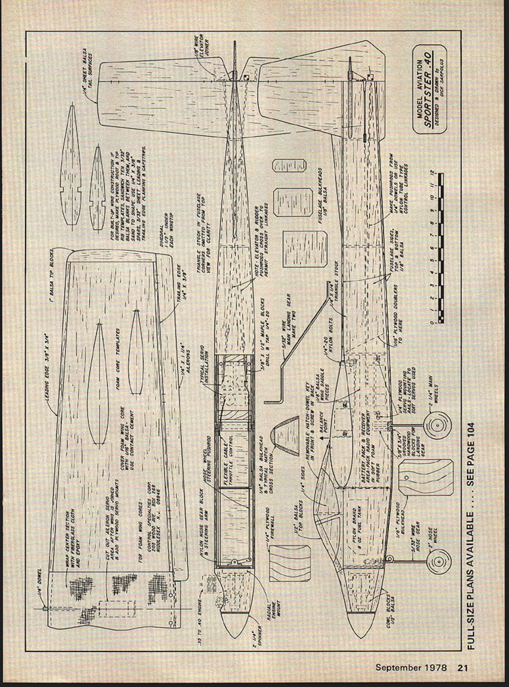
I feel the wing is the heart, the most important part of any airplane, so its design must be settled on first. For size, for a 35-40-powered model, the area chosen was 580 sq. in., large enough for light loading, not too big for snappy performance. Span is 58 in. Airfoil choice was easy: semi-symmetrical for more lift, easier takeoffs, and slower landings—but still capable of inverted maneuvering. Wing planform is tapered — I feel this to be an absolute must for good rolling performance. A barn door, constant-chord wing will never roll
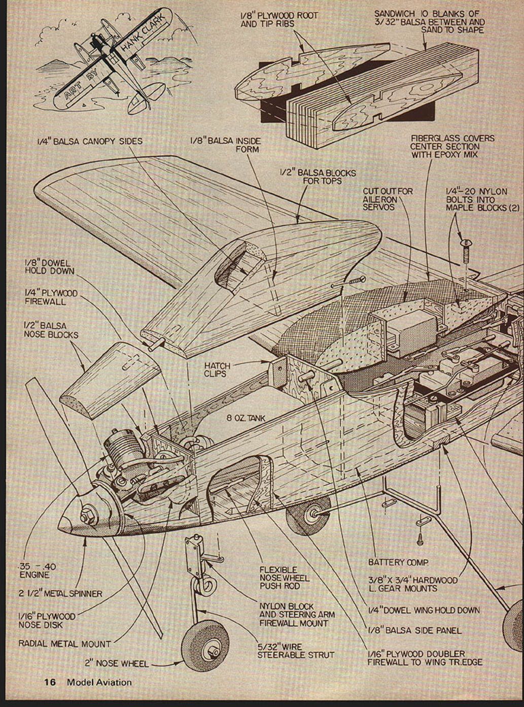
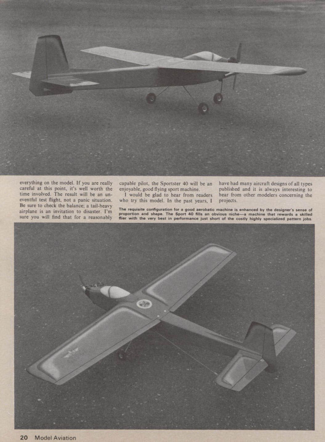
Top: The fighter type nose distinguishes this model from run-of-the-mill sport "pattern" types, but the model is as easy to build as, say, a Kaos. Above: "Come on down," Dick is suggesting. Why not fly a personalized ship? 1/8" PLYWOOD ROOT AND TIP RIBS
SANDWICH 10 BLANKS OF 3/32" BALSA BETWEEN AND SAND TO SHAPE
FIBERGLASS COVERS CENTER SECTION WITH EPOXY MIX
1/4" BALSA CANOPY SIDES
1/8" BALSA INSIDE FORM
1/2" BALSA BLOCKS FOR TOPS
CUT OUT FOR AILERON SERVOS
1/4"-20 NYLON BOLTS INTO MAPLE BLOCKS (2)
1/8" DOWEL HOLD DOWN
1/4" PLYWOOD FIREWALL
1/2" BALSA NOSE BLOCKS
HATCH CLIPS
8 OZ. TANK
.35 - .40 ENGINE
2 1/2" METAL SPINNER
1/16" PLYWOOD NOSE DISK
RADIAL METAL MOUNT
2" NOSE WHEEL
FLEXIBLE NOSE WHEEL PUSH ROD
NYLON BLOCK AND STEERING ARM FIREWALL MOUNT
5/32" WIRE STEERABLE STRUT
BATTERY COMP
3/8" X 3/4" HARDWOOD L. GEAR MOUNTS
1/4" DOWEL WING HOLD DOWN
1/8" BALSA SIDE PANEL
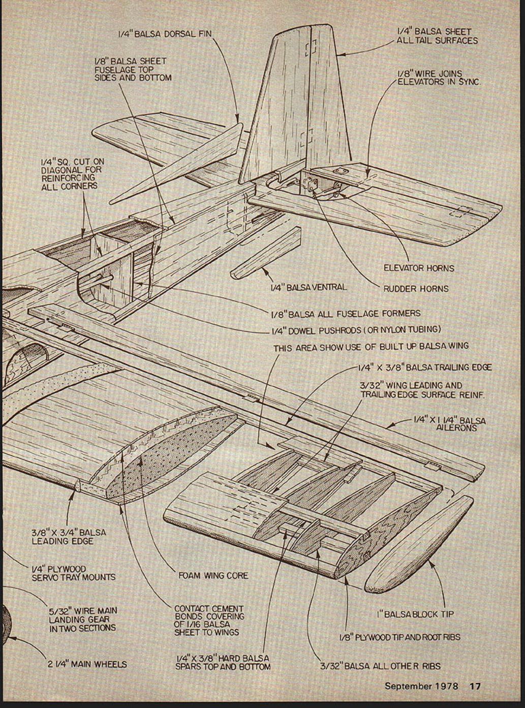
1/16" PLYWOOD DOUBLER FIREWALL TO WING TR. EDGE 1/4" BALSA DORSAL FIN
1/8" BALSA SHEET FUSELAGE TOP SIDES AND BOTTOM
1/4" SQ. CUT ON DIAGONAL FOR REINFORCING ALL CORNERS
1/8" BALSA SHEET ALL TAIL SURFACES
1/8" WIRE JOINS ELEVATORS IN SYNC
ELEVATOR HORNS
RUDDER HORNS
1/4" BALSA VENTRAL
1/8" BALSA ALL FUSELAGE FORMERS
1/4" DOWEL PUSHRODS (OR NYLON TUBING)
THIS AREA SHOWS USE OF BUILT-UP BALSA WING
1/4" x 3/8" BALSA TRAILING EDGE
3/32" WING LEADING AND TRAILING EDGE SURFACE REINF.
1/4" x 1/4" BALSA AILERONS
3/8" x 3/4" BALSA LEADING EDGE
1/4" PLYWOOD SERVO TRAY MOUNTS
FOAM WING CORE
CONTACT CEMENT BONDS COVERING OF 1/16" BALSA SHEET TO WINGS
5/32" WIRE MAIN LANDING GEAR IN TWO SECTIONS
2 1/4" MAIN WHEELS
1/4" x 3/8" HARD BALSA SPARS TOP AND BOTTOM
3/32" BALSA ALL OTHER RIBS
1/8" PLYWOOD TIP AND ROOT RIBS
1" BALSA BLOCK TIP as well as a tapered wing. Tapered wings are not necessarily more prone to tip stalls; the thickness of this airfoil is 16%, sufficient for reasonable slow flying characteristics. For even more protection against stalls, the wing could easily be built with several degrees of washout cut into the foam cores, although I felt this was not necessary.
Strip ailerons are used as their installation is easy and their performance is good. Foam core construction is used for speed of building, strength, true airfoil shape, etc. Most all clubs have members capable of cutting foam wing cores. If you must use a commercial source, I would suggest Control Specialties Corp., 205 Wood Ave. Box 268, Middlesex, NJ 08846. For those who prefer traditional built-up wing construction, ribs could be made by the "sandwich and sand to shape" method from the templates shown on the plans.
Fuselage next: shoulder wing configuration for a little more stability than a low wing, and more resistance to crash damage. A fairly long tail moment for control smoothness, a nose moment for the correct balance. The original model balanced as shown with no added ballast. The fuselage is of basic box construction; 1/8" balsa sides, 1/16" plywood doublers, triangle stock along the edges to permit rounding. The tricycle landing gear mounts in the fuselage; conventional coil nose gear, and torsion leg type main gear. I believe the wire main gear is more shock absorbent and tolerant of abuse than a sheet aluminum landing gear. Tail surfaces are sheet balsa, again a minimum of work, and styled to suit this designer.
The one area where the "minimum parts for easy construction" philosophy was abandoned in favor of styling is the engine cowl and canopy area. Instead of open nose blocks the engine area is blocked in and faired into a spinner. The engine can be mounted vertically or horizontally; I prefer to mount it canted at a 45-degree angle, which lowers the exhaust below the wing for a cleaner model but doesn't hang the muffler below the fuselage as a side mounted engine would. The canopy section also serves as a hatch for the fuel tank area; it is built-up of several pieces and shaped. I felt the additional work in these areas was worth it for the streamlining and somewhat different appearance of the forward canopy.
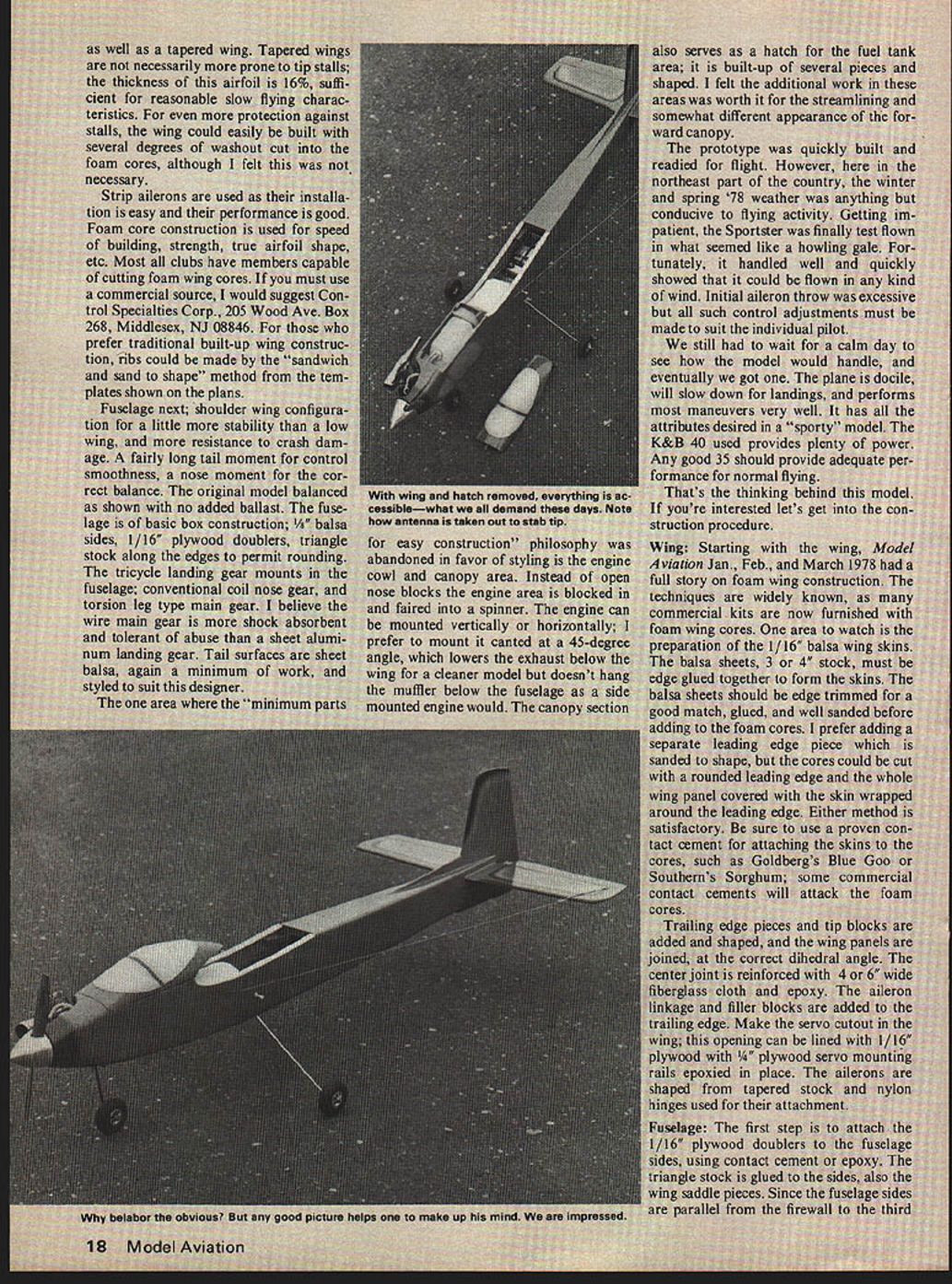
The prototype was quickly built and readied for flight. However, here in the northeast part of the country, the winter and spring '78 weather was anything but conducive to flying activity. Getting impatient, the Sportster was finally test flown in what seemed like a howling gale. Fortunately, it handled well and quickly showed that it could be flown in any kind of wind. Initial aileron throw was excessive but all such control adjustments must be made to suit the individual pilot.
We still had to wait for a calm day to see how the model would handle, and eventually we got one. The plane is docile, will slow down for landings, and performs most maneuvers very well. It has all the attributes desired in a "sporty" model. The K&B .40 used provides plenty of power. Any good .35 should provide adequate performance for normal flying.
That's the thinking behind this model. If you're interested let's get into the construction procedure.
Wing: Starting with the wing, Model Aviation Jan., Feb., and March 1978 had a full story on foam wing construction. The techniques are widely known, as many commercial kits are now furnished with foam wing cores. One area to watch is the preparation of the 1/16" balsa wing skins. The balsa sheets, 3 or 4" stock, must be edge glued together to form the skins. The balsa sheets should be edge trimmed for a good match, glued, and well sanded before adding to the foam cores. I prefer adding a separate leading edge piece which is sanded to shape, but the cores could be cut with a rounded leading edge and the whole wing panel covered with the skin wrapped around the leading edge. Either method is satisfactory. Be sure to use a proven contact cement for attaching the skins to the cores, such as Goldberg's Blue Goo or Southern's Sorghum; some commercial contact cements will attack the foam cores.
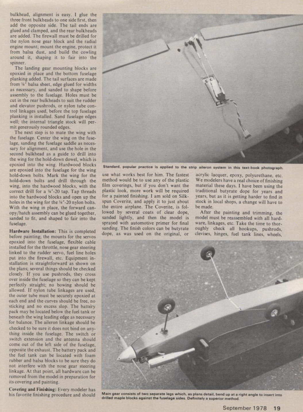
Trailing edge pieces and tip blocks are added and shaped, and the wing panels are joined, at the correct dihedral angle. The center joint is reinforced with 4 or 6" wide fiberglass cloth and epoxy. The aileron linkage and filler blocks are added to the trailing edge. Make the servo cutout in the wing; this opening can be lined with 1/16" plywood with 1/4" plywood servo mounting rails epoxied in place. The ailerons are shaped from tapered stock and nylon hinges used for their attachment.
Fuselage: The first step is to attach the 1/16" plywood doublers to the fuselage sides, using contact cement or epoxy. The triangle stock is glued to the sides, also the wing saddle pieces. Since the fuselage sides are parallel from the firewall to the third former. bulkhead alignment is easy. I glue the three front bulkheads to one side first, then add the opposite side. The tail ends are glued and clamped, and the rear bulkheads are added. The firewall must be drilled for the nylon nose gear block and the radial engine mount; mount the engine, protect it from balsa dust, and build the cowling around it, shaping it to fair into the spinner.
The landing gear mounting blocks are epoxied in place and the bottom fuselage planking added. The tail surfaces are made from 1/4" balsa sheet, edge glued for widths as necessary, and sanded to shape before assembly to the fuselage. Holes must be cut in the rear bulkheads to suit the rudder and elevator pushrods, or nylon tube control linkages used, before the top fuselage planking is installed. Sand fuselage edges well; the internal triangle stock will permit generously rounded edges.
The next step is to mate the wing with the fuselage. Center the wing on the fuselage, sanding the fuselage saddle as necessary for alignment, and use the hole in the second bulkhead as a guide to drill into the wing for the hold-down dowel, which is epoxied into the wing. Hardwood blocks are epoxied into the fuselage for the wing hold-down bolts. Mark the wing for the hold-down bolts and drill through the wing, into the hardwood blocks, with the correct drill for a 1/4"-20 tap. Tap threads into the hardwood blocks and open up the holes in the wing for the 1/4"-20 nylon bolts. With the wing in place, the forward canopy/hatch assembly can be glued together, sanded to fit, and shaped to fair into the fuselage.
Hardware Installation:
This is completed before painting; the mounts for the servos epoxied into the fuselage, flexible cable installed for the throttle, nose gear steering linked to the rudder servo, fuel line holes put into the firewall, etc. Equipment installation is straightforward as shown on the plans; several things should be checked closely. If you use pushrods, they cross over inside the fuselage so they can be kept perfectly straight; no bowing should be allowed. If nylon tube linkages are used, the outer tube must be securely epoxied at each end and the curves should be free, no sticking and no excess slop. The battery pack may be located below the fuel tank or beneath the wing leading edge as necessary for balance. The aileron linkage should be checked to be sure it does not bind on anything inside the fuselage. The switch or switch extension and the antenna should come out of the left side of the fuselage opposite the exhaust. The battery pack and the fuel tank can be located with foam rubber and balsa blocks to be sure they do not interfere with the nose gear steering linkage. At that point, all hardware can be removed from the model in preparation for its covering and painting.
Covering and Finishing:
Every modeler has his favorite finishing procedure and should use what works best for him. The fastest method would be to use any of the plastic film coverings, but if you don't want the plastic look, more work will be required for a painted finishing. I am sold on Silkspan Coverite, and apply it to just about the entire airplane. The Coverite is followed by several coats of clear dope, sanded lightly, and then the model is sprayed with automotive primer for final sanding. The finish colors can be butyrate dope, as was used on the original, or acrylic lacquer, epoxy, polyurethane, etc. We modelers have a real choice of finishing material these days. I have been using the traditional butyrate dope for years and years, but as it is getting harder to find in stock in local shops, a change will have to be made.
After the painting and trimming, the model must be reassembled with all hardware, linkages, etc. Take the time to thoroughly check all hookups, pushrods, clevises, hinges, fuel tank lines, wheels, everything on the model. If you are really careful at this point, it's well worth the time involved. The result will be an uneventful test flight, not a panic situation. Be sure to check the balance; a tail-heavy airplane is an invitation to disaster. I'm sure you will find that for a reasonably capable pilot, the Sportster 40 will be an enjoyable, good flying sport machine.
I would be glad to hear from readers who try this model. In the past years, I have had many aircraft designs of all types published and it is always interesting to hear from other modelers concerning the projects.
The requisite configuration for a good aerobatic machine is enhanced by the designer's sense of proportion and shape. The Sport 40 fills an obvious niche—a machine that rewards a skilled flier with the very best in performance just short of the costly highly specialized pattern jobs. FULL-SIZE PLANS AVAILABLE — SEE PAGE 104
Transcribed from original scans by AI. Minor OCR errors may remain.

