
Sportwagon Jr.
Jack Headley
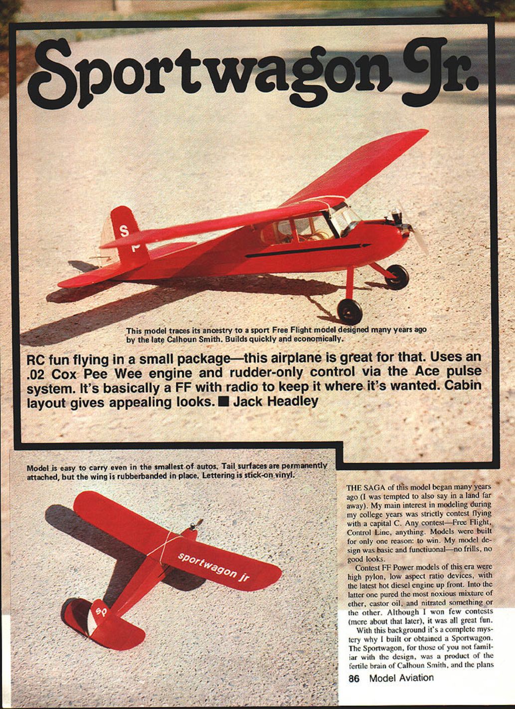
RC fun flying in a small package—this airplane is great for that. Uses an .02 Cox Pee Wee engine and rudder-only control via the Ace pulse system. It's basically a Free Flight with radio to keep it where it's wanted. Cabin layout gives appealing looks.
Background
The saga of this model began many years ago. My main interest in modeling during my college years was strictly contest flying with a capital C. Any contest—Free Flight, Control Line, anything. Models were built for only one reason: to win. My model design was basic and functional—no frills, no good looks.
Contest FF power models of this era were high pylon, low aspect-ratio devices, with the latest hot diesel engine up front. Into the latter one poured the most noxious mixture of ether, castor oil, and nitrated something or other. Although I won a few contests (more about that later), it was all great fun.
With this background it's a complete mystery why I built or obtained a Sportwagon. The Sportwagon, for those of you not familiar with the design, was a product of the fertile brain of Calhoun Smith, and the plans were published in a short-lived magazine in England during the Fifties.
The design was the antithesis of my type of model. It had a cabin, wheels, and a cavernous fuselage. However, it was a good flier. I used it for both fun and contest work, usually obtaining my consistent one max, out-of-sight, score. The best-remembered of this type of result was a flight at a contest in Huddersfield, which (as usual) went out-of-sight after a few minutes (the wind always blows in Huddersfield), and finally landed on a golf course in Halifax.
I can't recall what happened to the model in the end; however, a year or so ago I got the urge to remake the Sportwagon. A friend in Toronto happened to have a copy of the original English magazine, so I prevailed on him to Xerox a copy for me (thanks, Mike). Then I set about scaling it up.
However, as usual, my grasshopper mind took a left turn. Rather than remaking the full-sized bird, I decided to produce a single-channel version to fly in my local park. This single-channel model is the subject of this article.
Someday, however, I'll remake the original. Does anyone out there have an Elfin 1.8 diesel with the tubular tank in the back? I might need one.
Construction
The model shown in the plans is not just a scaled-down version of the original. I did quite a bit of redesign work and simplification, though I think I preserved the original flavor of its big brother. My prototype was built very leisurely during a rainy week, using one of the "slow" super glues. It was built primarily for the Ace pulse radio, but there's no reason why a small two-channel set couldn't have been used (with the addition of a small elevator on the back of the stabilizer). The following notes are strictly for the single-channel model.
Wing
- Build the wing initially as a single piece, then cut it into two halves and re-join at the correct dihedral angle.
- Pin down the lower main spar and trailing edge strip onto the plans.
- Make all the wing ribs in your preferred manner. (I make a hard balsa template, cut them all out quickly, then assemble in a block, sand, and saw out all the spar notches.)
- Glue all the ribs into place except the center and tip ribs, then add the leading edge strip.
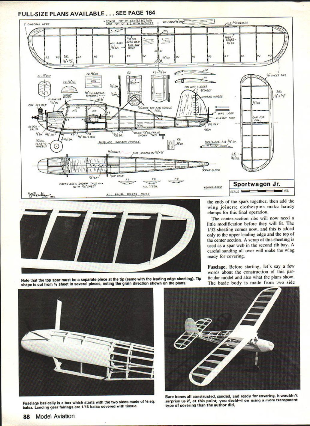
- Cut and add the 1/8" sheet wing tips next, followed by the tip ribs and the upper main spar.
Carefully cut the wing in half at the center, and sand the resulting spar ends to the correct bevel. Make the wing joiners from hard sheet.
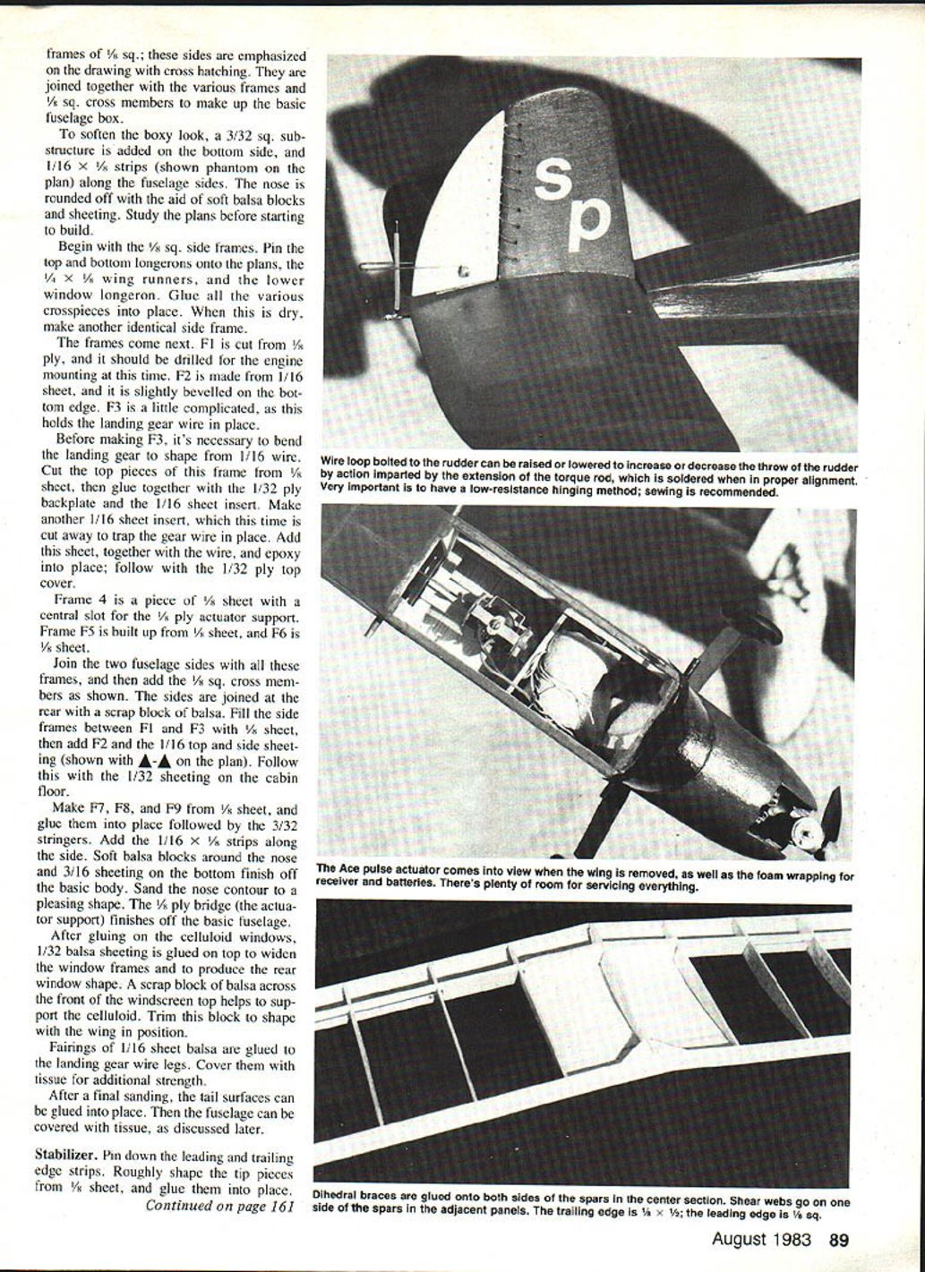
Re-join the wing pieces as follows: pin one wing half onto the plan and prop up the other wing tip on a solid block (I use a scrap off an old 2 x 4) until the correct height under the tip is found; in this case 4 in. Glue the ends of the spars together, add the wing joiners—clothespins make handy clamps. As a final operation the center-section ribs will need a little modification before the 1/32" sheeting is fitted. Now add the upper leading edge to the top center section. Scrap sheeting is used as the spar web in the second rib bay. Careful sanding will make the wing ready for covering.
Fuselage
Before starting, note that the basic body is made from two side pieces: frames of 1/4" sq.; these sides are emphasized on the drawing with cross-hatching. They are joined together with the various frames and 1/8" sq. cross members to make up the basic fuselage box.
To soften the boxy look, a 3/32" sq. sub-structure is added on the bottom side, and 1/16" x 1/8" strips (shown phantom on the plan) are added along the fuselage sides. The nose is rounded off with the aid of soft balsa blocks and sheeting. Study the plans before starting to build.
- Begin with the 1/8" sq. side frames. Pin the top and bottom longerons onto the plans, the 1/4" x 1/8" wing runners, and the lower window longeron. Glue all the various crosspieces into place. When dry, make another identical side frame.
- Make the frames:
- F1 is cut from 3/32" ply and should be drilled for the engine mounting at this time.
- F2 is made from 1/16" sheet and is slightly beveled on the bottom edge.
- F3 is a little complicated, as it holds the landing gear wire in place.
Before making F3, bend the landing gear to shape from 1/16" wire. Cut the top pieces of F3 from 1/8" sheet, then glue together with the 1/32" ply backplate and a 1/16" sheet insert. Make another 1/16" sheet insert, this time cut away to trap the gear wire in place. Add this sheet together with the wire and epoxy into place; follow with the 1/32" ply top cover.
Frame F4 is a piece of 1/8" sheet with a central slot for the 1/8" ply actuator support. Frame F5 is built up from 1/8" sheet, and F6 is 1/8" sheet.
Join the two fuselage sides with all these frames, then add the 1/8" sq. cross members as shown. The sides are joined at the rear with a scrap block of balsa. Fill the side frames between F1 and F3 with 1/8" sheet, then add F2 and the 1/16" top and side sheeting (shown on the plan). Follow this with the 1/32" sheeting on the cabin floor.
Make F7, F8, and F9 from 1/8" sheet and glue them into place, followed by the 3/32" stringers. Add the 1/16" x 1/8" strips along the side. Soft balsa blocks around the nose and 3/16" sheeting on the bottom finish off the basic body. Sand the nose contour to a pleasing shape. The 1/8" ply bridge (the actuator support) finishes off the basic fuselage.
After gluing on the celluloid windows, glue 1/32" balsa sheeting on top to widen the window frames and to produce the rear window shape. A scrap block of balsa across the front of the windscreen top helps support the celluloid—trim this block to shape with the wing in position.
Fairings of 1/16" sheet balsa are glued to the landing gear wire legs. Cover them with tissue for additional strength.
After a final sanding, the tail surfaces can be glued into place. Then the fuselage can be covered with tissue, as discussed later.
Stabilizer
Pin down the leading and trailing edge strips. Roughly shape the tip pieces from 1/8" sheet and glue them into place. Place all the ribs, followed by the 1/8" sq. spar. Be sure to leave a 1/8" gap between the center ribs so that the fin can be inserted later. When dry, remove from the building board and sand the tip pieces to final shape. Then sand all over until smooth.
Fin and Rudder
These are cut from 3/32" sheet—firm, but not too heavy. Sand all the edges round and the sides smooth, then hinge together. The photos and plan show a sewn hinge; I've found this to be the most effective for a pulsed rudder. The hinge must be almost free of friction, as the pulser isn't very powerful. Be careful with this step and don't end up with an unbendable hinge!
My method is to drill all the required holes in the fin and rudder with a 1/16" drill. Then I sew the rudder to the fin with carpet thread in the pattern shown on the plan. When finished, stabilize the thread with a small drop of glue at each hole.
Assembly
After the stabilizer is covered (but not doped), remove the tissue from the center slot and glue the fin into place. Make sure that the rudder doesn't bind on the top of the stabilizer. This unit can now be glued to the uncovered fuselage.
Cover the fuselage next.
Finishing
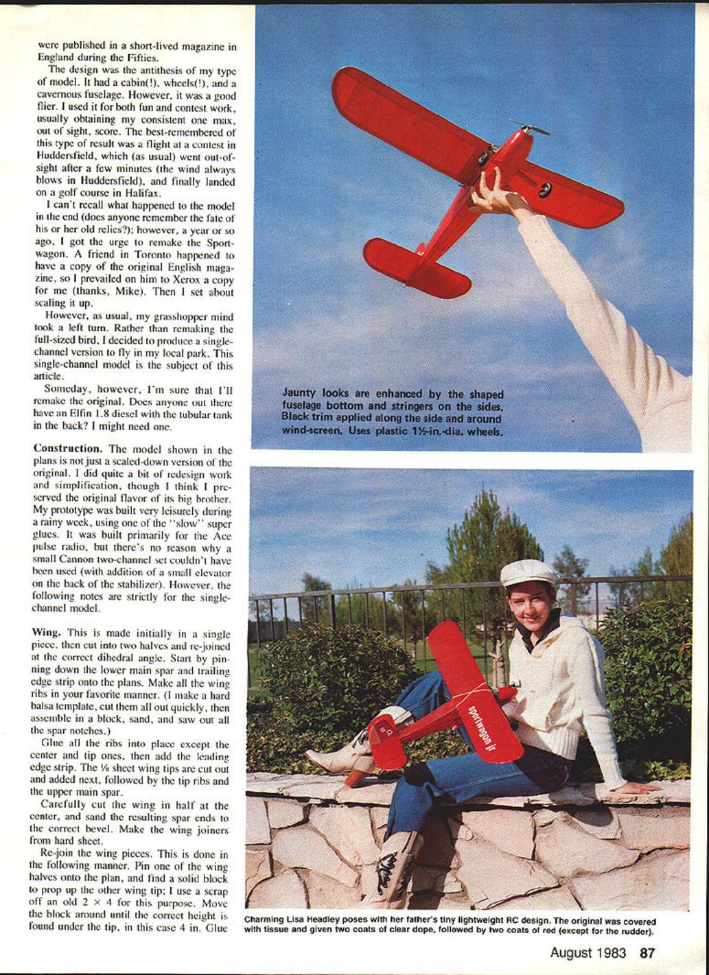
Cover with a lightweight tissue. After water-shrinking, apply a couple of coats of clear dope. A further two coats of color should produce a durable finish. My prototype was painted red all over, with the exception of the rudder. Black trim was applied around the windscreen and along the body. The name and other letters were done with stick-on vinyl.
Radio Installation
The front portion of the cabin between F3 and F4 is large enough for the battery and receiver, which should be well wrapped in foam rubber. The actuator is bolted to the 1/8" ply "bridge" between F4 and F5. A suitable nut should be epoxied under this plywood strip to make it easier to attach and remove the actuator.
The torque rod is bent from 1/16" wire. It is attached to the actuator with a scrap of plastic tubing at the front end and held in place at the back with the 1/16" ply bearing. The rudder actuator wire is soldered onto the torque rod on final installation—be sure this is correctly aligned.
Keep checking during all these operations to ensure that everything is as free of friction as possible. The final item is the wire loop attached to the rudder. This is held in place with a small bolt. Rudder "throw" is changed by moving this loop up and down.
Flight Testing
I treat single-channel RC models essentially as Free Flights. I use the rudder control to occasionally nudge the model back to home base. It is possible to do loops and stunts with complicated sequences of rudder lefts and rights, but I prefer the sport flying aspect of these models—and leave all the aerobatics for models with a few more channels.
- Set up the balance with a few test glides. Check that the center of gravity is roughly in the position shown on the plans, then try a few hand glides.
- Make corrections as necessary—a little nose weight for a stalling glide, and vice versa. Shimming the wing is an alternative to using ballast.
- When the glide seems about right, try some power flights and then make the final corrections to the rudder throw and glide path.
After this it should just be fun. Enjoy!
Editor's Note
We are saddened to report that the author, Jack Headley, succumbed to a heart attack a few weeks before this article was scheduled for printing. Through the years many of Jack's fine articles and designs have appeared in this and other model magazines. Our sympathy goes to Jack Headley's family and friends on this loss.
Transcribed from original scans by AI. Minor OCR errors may remain.

