
Spullet
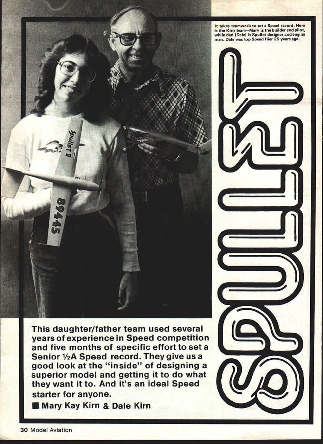
This daughter/father team used several years of experience in Speed competition and five months of specific effort to set a Senior 1/2A Speed record. They give us a good look at the “inside” of designing a superior model and getting it to do what they want it to. And it’s an ideal Speed starter for anyone.
Mary Kay Kirn & Dale Kirn MARY KAY: Little did I know when I first started competing in contests that I would ever hold a national AMA Speed record. The thought never occurred to me until last year, when I was a junior in high school. Up until that time, competing was just for the fun of it.
I started flying model airplanes using Mono-Line control when I was eight years old. Two-line flying started about a year later. At my first Nats in 1971 (Glenview, IL), I was lucky enough to place 4th in Junior 1/2A Profile Proto. Remember that those were the days when there were so many contestants in one event that you were lucky to get all your flight attempts in before the time limit at the end of the day. In 1973 at Oshkosh, WI, my dad and I entered 1/2A Proto Speed in Open as a team and placed first. I placed 5th in Junior 1/2A Profile at the ’75 Nats, but still wasn’t into the more serious business of setting a record. In 1977 I tried to get more serious in 1/2A Speed, but still wasn’t fast enough to beat a certain Bussell at the Nats that year. A year later I decided to really work at it and go for a national record in Senior 1/2A Speed.
Spullet I (derived from “faster than a speeding bullet”) was born in December of 1978 and was soon ready for testing. Every weekend was dedicated to this purpose. After flying Spullet a few times and getting the feel of it, we were ready to get into the serious business of making it go fast. We tested propellers by using a different one for each flight. After we knew which props were the best for competition, we started testing out different engine-prop combinations in different types of weather. When we got up to 100.01 mph without the “good” fuel, I was certain that a record would be set with the right weather conditions, fuel, and engine-prop combination. We were then ready to try out Spullet at an official contest. That came on May 6, 1979 at an AA meet in Santa Ana, CA.
The sky that morning was overcast and cool, and my first flight of 95 mph wasn’t exactly what we were looking for. The plane had to beat the 102 mph barrier to get the record. A few hours later we tried it again, but no luck. After lunch, the sky began to clear, and the air was getting warmer. I decided to give it one more try, knowing deep down that this time Spullet would come through.
Because of all the practice in the pylon, I always knew about how fast the plane was moving; this time it was really going! When the flight was over, I was congratulated secretly by Dad who was also timing it for his own information. He said I had done it. Back at the official table, the timers were calculating the official time—108.13 mph. Now it was time for the supporting flight required for records by AMA rules. I hoped for a good clocking on my first attempt so that my nervousness would disappear. On the first try, Spullet had come through again—the time was 104.06. My 108.13 was official!
About a week later, I started to build a backup plane for the Nats in Lincoln, NE. It wasn’t finished in time, so I hoped that nothing major would happen to Spullet I while competing. The day of 1/2A Speed was partly cloudy in the morning and not too windy (the forecast was for rain), so I decided to put in a flight before the weather got any worse. My first flight at 103.13 mph was also my best flight, and it was good enough for first place. It was still within 5 mph of my record.
Spullet II was finished in late October. A contest was coming up in December, and I wanted to see if Spullet II, with a few minor modifications from the original, could break my own record. Again the weekends of practice and experimentation began. It looked as if Spullet I and Spullet II were nearly the same in performance. At the first contest entered in Van Nuys, CA, Spullet II was my choice to fly officially, and Spullet I was my backup. Spullet II turned 107.10 mph on its first official flight! That was 99% of my record with Spullet I, which proved the design had the reliability we were looking for in a 1/2A Speed plane.
In nearly all my practice flights the takeoff is with my wrist in the pylon. This prevents whipping it up to speed like most everyone else does. But in this way we are able to precisely and consistently evaluate one change at a time in prop, fuel, etc.
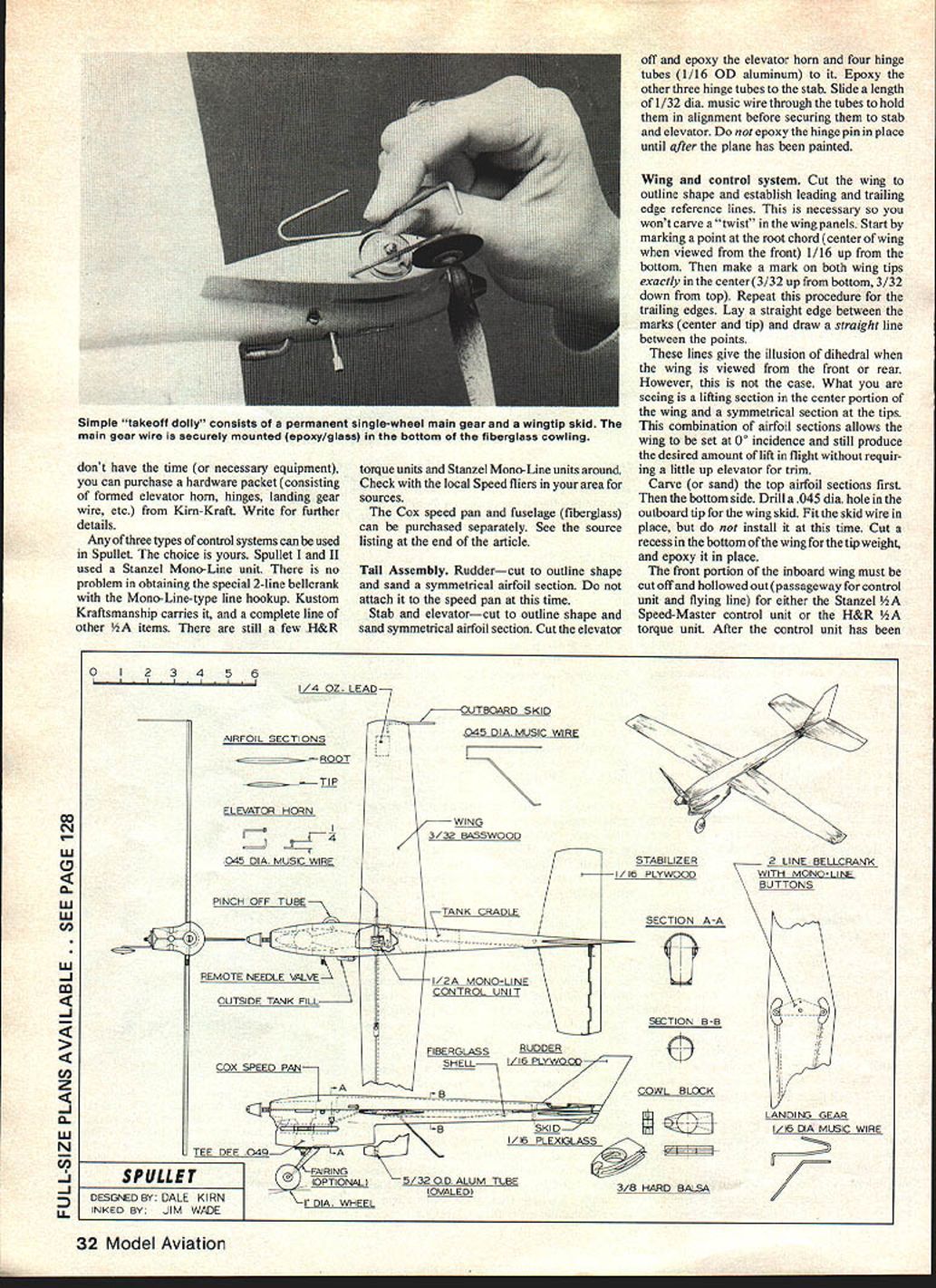
Spullet’s design is a bit different from most Speed planes in a number of respects. Spullet is a sturdy plane (about twice the size of a conventional 1/2A Speed plane) that flies excellently in wind because of its extra weight (7½ oz.). It is a cross between a 1/2A Proto and a 1/2A Rat Racer, incorporating the best features of both, plus a little extra—that being the cowl design and the control system. Mono-Line is used instead of a torque unit. A front wheel, tail skid, and outboard wing skid are used (instead of a dolly) for trouble-free takeoffs—which encourage practice flying. An interesting sidelight is that I had to learn to whip for landings so as to avoid nicking the best props and wearing down the skids.
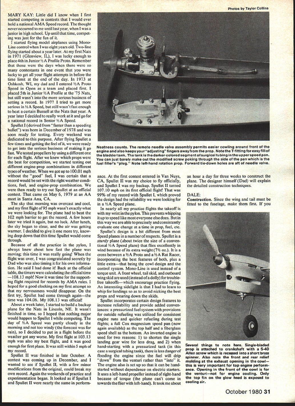
Spullet incorporates certain design features to increase reliability and provide added conveniences: a pressurized fuel system with provisions for outside refueling was utilized for consistent engine runs and quicker refueling during test flights; a full Cox magnesium speed pan (now again available) as the top half and a fiberglass speed shell as the bottom. An inverted engine is used for two reasons: 1) to shorten the single landing gear wire for less drag, and 2) when hand-starting with a pressurized tank (in this case a surgical tubing tank), there is less danger of flooding the engine since the fuel will drip “down” from the venturi rather than “into” it. The engine also is set up so that it can be hand-started without dependence on electric starters. It uses a left-hand propeller instead of right-hand because of torque (the plane can’t come in towards the flier with left-hand). It took me about an hour a day for three weeks to construct the plane. The designer himself (Dad) will explain the detailed construction techniques.
DALE:
Construction. Since the wing and tail must be fitted to the fuselage, make them first. If you don’t have the time (or necessary equipment), you can purchase a hardware packet (consisting of formed elevator horn, hinges, landing gear wire, etc.) from Kirn-Kraft. Write for further details.
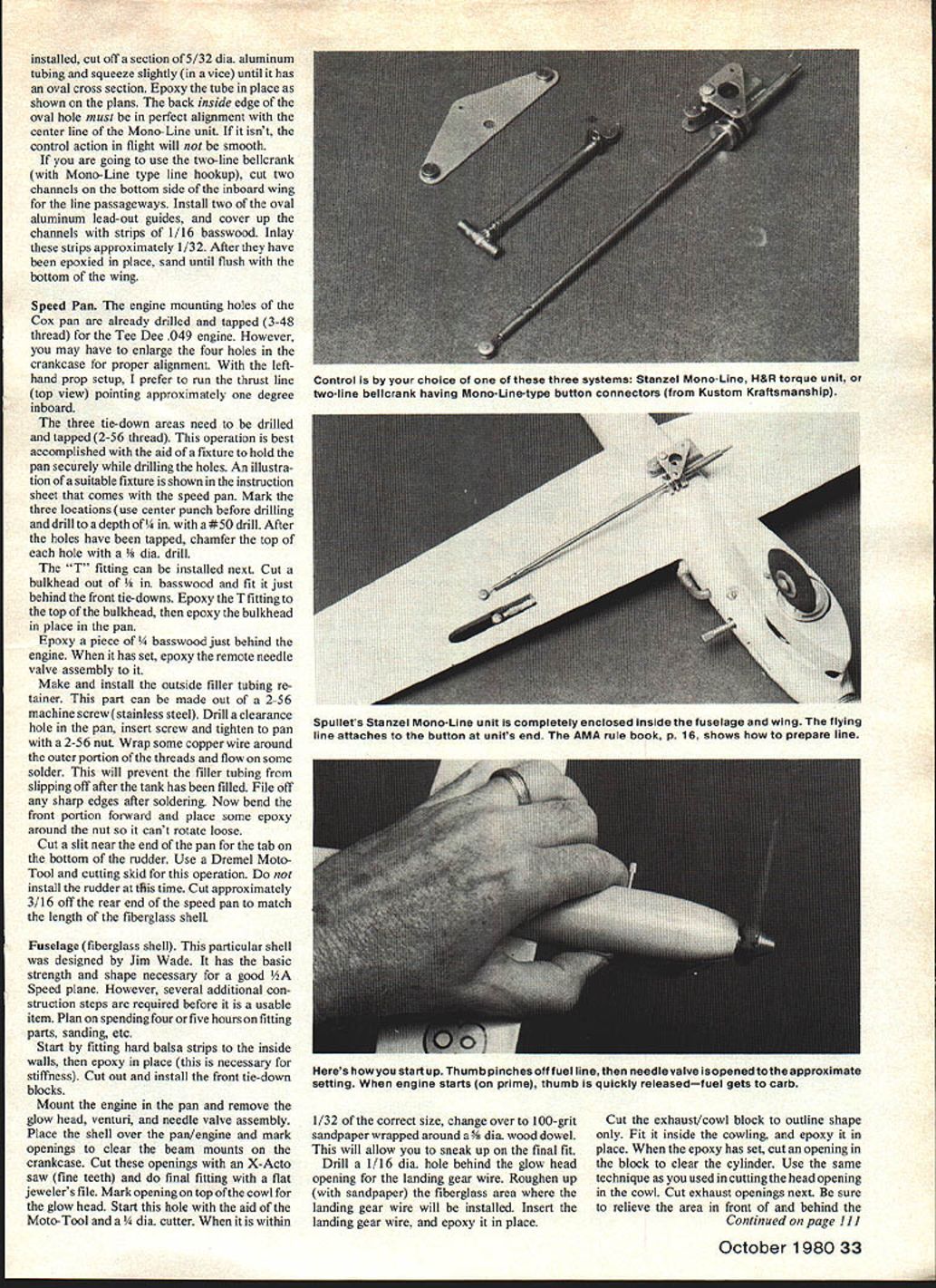
Any of three types of control systems can be used in Spullet. The choice is yours. Spullet I and II used a Stanzel Mono-Line unit. There is no problem in obtaining the special 2-line bellcrank with the Mono-Line-type line hookup. Kustom Kraftsmanship carries it, and a complete line of other 1/2A items. There are still a few H&R torque units and Stanzel Mono-Line units around. Check with the local Speed fliers in your area for sources.
The Cox speed pan and fuselage (fiberglass) can be purchased separately. See the source listing at the end of the article.
Tail Assembly.
Rudder—cut to outline shape and sand a symmetrical airfoil section. Do not attach it to the speed pan at this time.
Stab and elevator—cut to outline shape and sand symmetrical airfoil section. Cut the elevator off and epoxy the elevator horn and four hinge tubes (1/16 OD aluminum) to it. Epoxy the other three hinge tubes to the stab. Slide a length of 1/32 dia. music wire through the tubes to hold them in alignment before securing them to stab and elevator. Do not epoxy the hinge pin in place until after the plane has been painted.
Wing and control system.
Cut the wing to outline shape and establish leading and trailing edge reference lines. This is necessary so you won’t carve a “twist” in the wing panels. Start by marking a point at the root chord (center of wing when viewed from the front) 1/16 up from the bottom. Then make a mark on both wing tips exactly in the center (3/32 up from bottom, 3/32 down from top). Repeat this procedure for the trailing edges. Lay a straight edge between the marks (center and tip) and draw a straight line between the points.
These lines give the illusion of dihedral when the wing is viewed from the front or rear. However, this is not the case. What you are seeing is a lifting section in the center portion of the wing and a symmetrical section at the tips. This combination of airfoil sections allows the wing to be set at 0° incidence and still produce the desired amount of lift in flight without requiring a little up elevator for trim.
Carve (or sand) the top airfoil sections first. Then bottom-side. Drill a .045 dia. hole in the outboard tip for the wing skid. Fit the skid wire in place, but do not install it at this time. Cut a recess in the bottom of the wing for the tip weight, and epoxy it in place.
The front portion of the inboard wing must be cut and hollowed out (passageway for control unit and flying line) for either the Stanzel 1/2A Speed-Master control unit or the H&R 1/2A torque unit. After the control unit has been installed, cut off a section of 5/32 dia. aluminum tubing and squeeze slightly (in a vise) until it has an oval cross section. Epoxy the tube in place as shown on the plans. The back inside edge of the oval hole must be in perfect alignment with the center line of the Mono-Line unit. If it isn’t, the control action in flight will not be smooth.
If you are going to use the two-line bellcrank (with Mono-Line type line hookup), cut two channels on the bottom side of the inboard wing for the line passageways. Install two of the oval aluminum lead-out guides, and cover up the channels with strips of 1/16 basswood. Inlay these strips approximately 1/32. After they have been epoxied in place, sand until flush with the bottom of the wing.
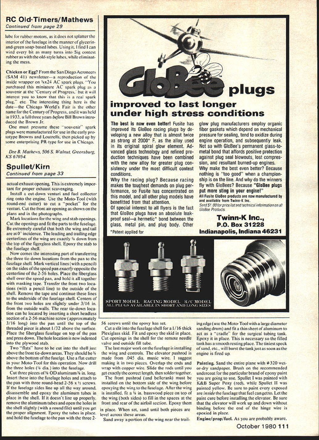
Speed Pan.
The engine mounting holes of the Cox pan are already drilled and tapped (3-48 thread) for the Tee Dee .049 engine. However, you may have to enlarge the four holes in the crankcase for proper alignment. With the left hand prop setup, I prefer to run the thrust line (top view) pointing approximately one degree inboard.
The three tie-down areas need to be drilled and tapped (2-56 thread). This operation is best accomplished with the aid of a fixture to hold the pan securely while drilling the holes. An illustration of a suitable fixture is shown in the instruction sheet that comes with the speed pan. Mark the three locations (use center punch before drilling) and drill to a depth of 1/8 in. with a #50 drill. After the holes have been tapped, chamfer the top of each hole with a 1/8 dia. drill.
The “T” fitting can be installed next. Cut a bulkhead out of 1/8 in. basswood and fit it just behind the front tie-downs. Epoxy the T fitting to the top of the bulkhead, then epoxy the bulkhead in place in the pan.
Epoxy a piece of 1/4 basswood just behind the engine. When it has set, epoxy the remote needle valve assembly to it.
Make and install the outside filler tubing retainer. This part can be made out of a 2-56 machine screw (stainless steel). Drill a clearance hole in the pan, insert screw and tighten to pan with a 2-56 nut. Wrap some copper wire around the outer portion of the threads and flow on some solder. This will prevent the filler tubing from slipping off after the tank has been filled. File off any sharp edges after soldering. Now bend the front portion forward and place some epoxy around the nut so it can’t rotate loose.
Cut a slit near the end of the pan for the tab on the bottom of the rudder. Use a Dremel Moto-Tool and cutting skid for this operation. Do not install the rudder at this time. Cut approximately 3/16 off the rear end of the speed pan to match the length of the fiberglass shell.
Fuselage (fiberglass shell).
This particular shell was designed by Jim Wade. It has the basic strength and shape necessary for a good 1/2A Speed plane. However, several additional construction steps are required before it is a usable item. Plan on spending four or five hours on fitting parts, sanding, etc.
Start by fitting hard balsa strips to the inside walls, then epoxy in place (this is necessary for stiffness). Cut out and install the front tie-down blocks.
Mount the engine in the pan and remove the glow head, venturi, and needle valve assembly. Place the shell over the pan/engine and mark openings to clear the beam mounts on the crankcase. Cut these openings with an X-Acto saw (fine teeth) and do final fitting with a flat jeweler’s file. Mark opening on top of the cowl for the glow head. Start the hole with the aid of the Moto-Tool and a 1/4 dia. cutter. When it is within 1/32 of the correct size, change over to 100-grit sandpaper wrapped around a 3/8 dia. wood dowel. This will allow you to sneak up on the final fit.
Drill a 1/16 dia. hole behind the glow head opening for the landing gear wire. Roughen up (with sandpaper) the fiberglass area where the landing gear wire will be installed. Insert the landing gear wire, and epoxy it in place.
Cut the exhaust/cowl block to outline shape only. Fit it inside the cowling, and epoxy it in place. When the epoxy has set, cut an opening in the block to clear the cylinder. Use the same technique as you used in cutting the head opening in the cowl. Cut exhaust openings next. Be sure to relieve the area in front of and behind the cylinder. actual exhaust opening. This is extremely important for proper exhaust scavenging.
Install a cut-down venturi and fuel collector ring onto the engine. Use the Moto-Tool (with round-end cutter) to cut a “pocket” for the venturi. Cut the front air opening as shown on the plans and in the photographs.
Mark locations for the wing and stab openings. Cut the openings and fit the parts to the fuselage. Be extremely careful that both the wing and tail are at 0 incidence. The leading and trailing edge centerlines of the wing are exactly 1/8 down from the top of the fiberglass shell. Epoxy the stab to the fuselage shell.
Now comes the interesting part of transferring the three tie-down locations from the pan to the fuselage shell. Mark vertical lines (with a pencil) on the sides of the speed pan exactly opposite the centerline of the 2-56 holes. Place the fiberglass shell over the speed pan, and hold it all together with masking tape. Transfer the front two locations (with a pencil line) to the outside of the shell. Remove the tape and continue these lines to the underside of the fuselage shell. Centers of the front two holes are slightly under 3/16 in. from the outside walls. The rear tie-down location can be located by inserting a short headless section of a 2-56 machine screw (approximately 3/16 long) into the pan until the top of the threaded piece is about 1/32 above the surface. Place the fiberglass fuselage on top of the pan and press down. The hole location is now indented into the plywood stab.
Two “flats” have to be cut into the shell just above the front tie-down areas. They should be 1/8 above the bottom of the fuselage. Use a flat cutter in your Moto-Tool for this operation. Now drill the three holes (#36 dia.) into the fuselage.
Cut three pieces of 1/8 OD aluminum x 1 in. long. Insert these into the fuselage holes and attach to the pan with three round-head 2-56 x 1/2 screws. If the fuselage sides line up with the pan all the way around, disassemble and epoxy the aluminum tubes in place in the shell. If it doesn’t line up properly, remove the aluminum tubes and open the holes in the shell slightly (with a round file) until you get the proper alignment. Epoxy the tubes in place, and hold the fuselage to the pan with three 2-56 screws until the epoxy has set.
Cut a slit into the fuselage shell for a 1/16 thick plexiglass skid. Fit and epoxy the skid in place. Cut openings in the shell for the remote needle valve and outside fill tube.
The last major work on the fuselage is installing the wing and controls. The elevator pushrod is made from .045 dia. music wire. I suggest making it in two pieces. Overlap the ends and wrap with copper wire. Slide the rods until you get exactly the correct length, then solder together.
The front pushrod (and bellcrank) must be installed on the bottom side of the wing before epoxying the wing to the fuselage. After the wing is installed, fit a 1/8 basswood piece on top of the wing (both sides) to fill in the spaces at the front and rear of the airfoil section. Epoxy them in place. When set, sand until both pieces are level across these areas.
Sand away a portion of the wing near the trailing edge (use the Moto-Tool with a large diameter sanding drum) and fit a thin sheet of aluminum to act as a “cradle” for the surgical tubing tank. Epoxy it in place. This is necessary so the filled tank has a smooth resting place. The tiniest speck of sand, etc., will burst the tank just as soon as the engine is fired up.
Painting. Sand the entire plane with #320 wet-or-dry sandpaper. Brush on the recommended undercoat for the particular brand of epoxy paint you are going to use. Spullet I was painted with K&B Super Poxy (red), while Spullet II was painted yellow. Be sure to paint every exposed area inside the fuselage that fuel can get to. Let the paint cure before installing the elevator. Be sure that the elevator will work up and down without binding before the end of the hinge wire is epoxied in place.
Engine/prop/fuel. As you are probably aware, not all Tee Dee .049s run the same. I recommend that you start off with a stock engine and fly the plane a few times to become familiar with the flying characteristics. The engines used in Spullet were set up with a left-hand crankshaft, and all test flights were with a Cox 4½-4 left-hand prop. This is the prop used on the Cox ready-to-fly WW I biplanes. Later on, single-blade props were tried. A hand-carved wood prop (single blade) of 4.9 dia. x 4.5 pitch was used to set the record. Jim Wade had an excellent article (Eagle I) published in the May 1976 issue of Model Aviation. This article has plans for constructing the single-blade prop he used to set a Senior ½A Speed record at 108.27 mph. It also has some very helpful hints on how his Tee Dee .049 was set up.
In addition to Wade’s article, I would highly recommend you get in touch with Gene Hempel (P&G Metal Shop) for his price on a chromed crankshaft. It is definitely worth the effort. (See address at end of article.)
On the record-setting flight, Spullet I was using a venturi hole of .150 dia. and the following fuel mix: 65% nitromethane, 10% castor oil, 8% synthetic oil (Paraplex) and 17% propylene oxide. A stock 1702 Cox glow head and one head gasket was also used. A “shaved” head will add some power, but they are not always reliable. I suggest staying with standard heads until you are getting consistent flights.
Sources of various parts your dealer may not have in stock:
- A-1 speed pan: Cox Hobbies, 1505 E. Warner Ave., Santa Ana, CA 92702.
- 2A speed shell (fiberglass): John Newton, 2154 Los Padres, Rowland Heights, CA 91745.
- Hardware packet for Spullet: Kim-Kraft, P.O. Box 785, Anaheim, CA 92805.
- Chromed shaft fitted to crankcase: P&G Metal Shop, 301 N. Yale Dr., Garland, TX 75042.
- Reworked Tee Dee .049 engines, 2-line bellcrank, lines, etc.: Kustom Kraftsmanship, P.O. Box 2699, Laguna Hills, CA 92653.
Transcribed from original scans by AI. Minor OCR errors may remain.

