
Staggerwing Beech
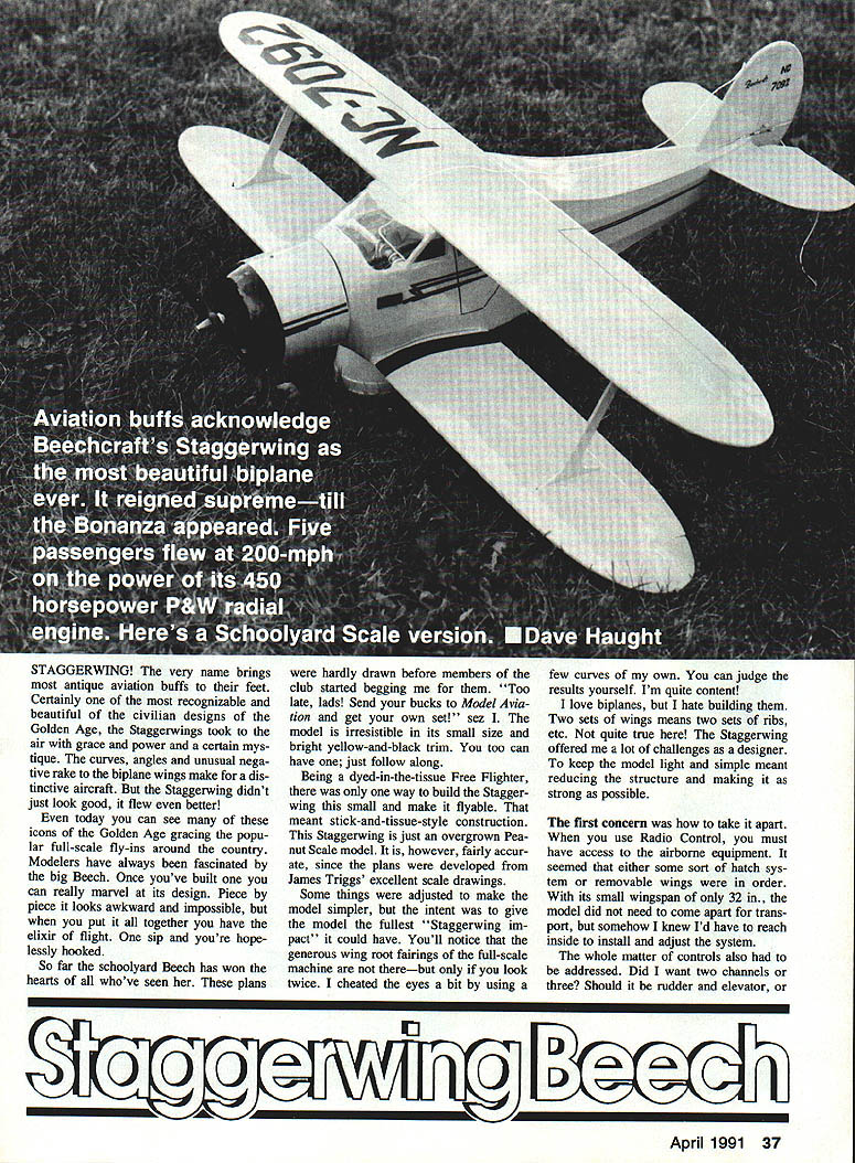
STAGGERWING! The very name brings most antique aviation buffs to their feet. Certainly one of the most recognizable and beautiful civilian designs of the Golden Age, the Staggerwings flew with grace, power and a certain mystique. The curves, angles and unusual negative rake of the biplane wings make for a distinctive aircraft. But the Staggerwing didn't just look good — it flew even better.
Even today you can see many of these icons of the Golden Age at full-scale fly-ins around the country. Modelers have always been fascinated by the big Beech. Once you've built one you can really marvel at its design. Piece by piece it looks awkward and impossible, but when you put it all together you have the elixir of flight. One sip and you're hopelessly hooked.
These plans were quickly in demand. The model is irresistible in its small size and yellow-and-black trim. You too can have one; just follow along.
Design considerations
- The model is essentially a stick-and-tissue free-flighter style build — a slightly overgrown Peanut Scale model — based on James Triggs' scale drawings with some adjustments to simplify construction.
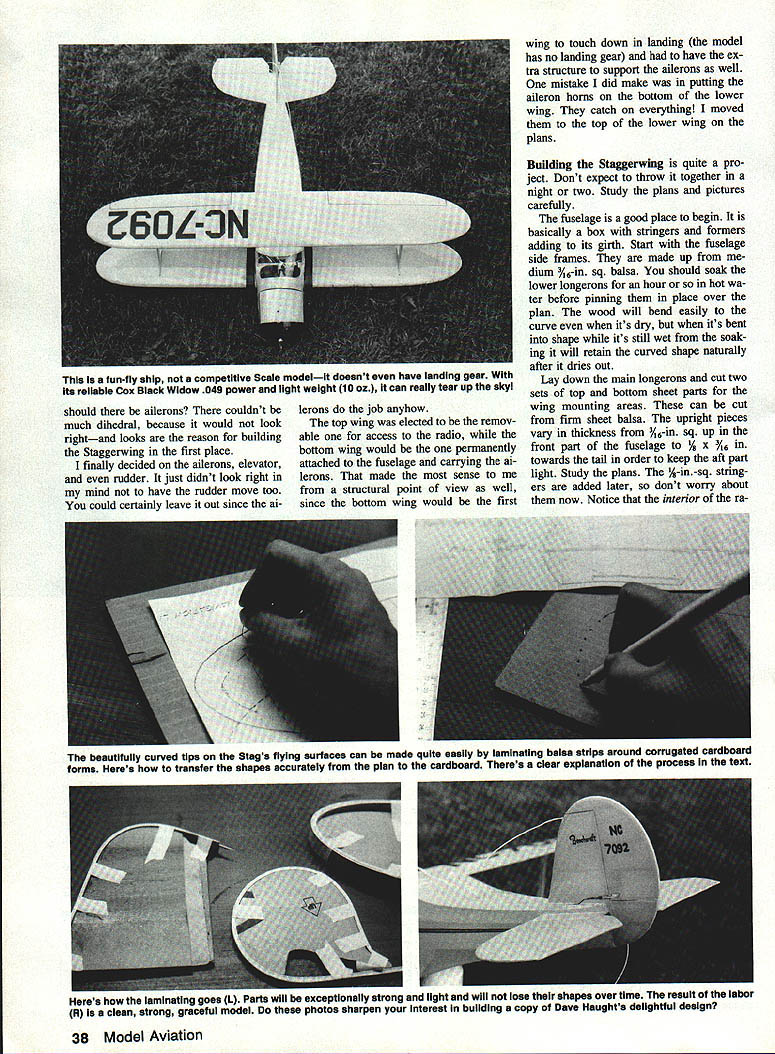
- No landing gear is used; the model lands on the lower wing and fuselage, so structural reinforcement is necessary where the lower wing and ailerons attach.
- Radio and controls:
- I chose three channels: ailerons, elevator and rudder. Ailerons do most of the job, but I preferred having rudder movement.
- The top wing is removable for access to the radio; the bottom wing is permanently attached and carries the ailerons (structurally sensible since the bottom wing contacts the ground first).
- Aileron horns originally placed on the bottom of the lower wing caught on everything; they were moved to the top of the lower wing in the plans.
Construction overview
Building the Staggerwing is a project — don't expect to throw it together in a night or two. Study the plans and photos carefully. Begin with the fuselage, then move to the tail and wings. Reduce structure where possible while keeping it strong.
Fuselage
- Materials and initial prep:
- Start the fuselage side frames from medium 3/16-in. square balsa.
- Soak the lower longerons in very hot water for an hour before pinning over the plan — the wood bends easily when wet and retains the shape when dry.
- Cut two sets of main longerons (top and bottom). Sheet parts in the wing-mounting areas can be cut from firm sheet balsa.
- Upright pieces vary in thickness: 3/16-in. square up front, tapering to 1/8-in. (or 1/16-in.) toward the tail to keep the aft part light. Study the plans; 1/8-in.-sq. stringers are added later.
- Side-frame assembly:
- Build the two fuselage side frames simultaneously, one atop the other, as is common for rubber-power fuselages. When glue joints are dry and soaked longerons have dried, separate the halves and trim excess.
- Glue in interior sheeting from 1/16-in. sheet at this point.
- Joining the sides and shaping:
- Locate former station "H" on the side view. From that point to the trailing edge of the upper wing the fuselage width is constant.
- Cut several 3/16-in. cross-members and connect the two sides together. After glue sets, carefully pull the fuselage sides together toward the tail and glue in crossmembers at the leading edge of the stabilizer.
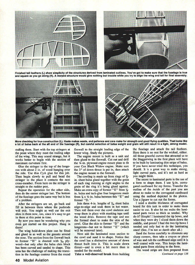
- Notch and bend the rearmost longerons to form correct curvature in plan view. Use a razor saw to cut almost through the longerons from the inside, then bend to shape. Check squareness often.
- Nose and firewall area:
- Study the top view to cut and angle the longerons to meet the firewall. Cut out former "F" and glue the longerons into its upper notches.
- Fill the lower nose section with a soft-to-medium balsa block to absorb landing shock and transfer loads to wing and fuselage.
- Cut and glue formers "G" and "H", remaining crossmembers and add side stringers.
- Sheeting and radio area:
- The radio area is sheeted after side frames are lifted from the plan.
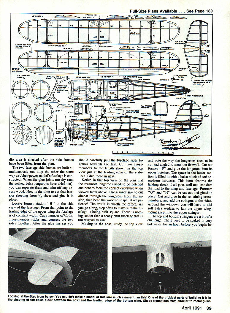
- The section from the firewall back to former "H" is sheathed with 1/16-in. plywood — but only after carving and sanding the balsa skin block to shape to transition from the round firewall to the straight leading edge of the lower wing.
Stringers and shaping
- Top and bottom stringers are challenging — soak them in very hot water for an hour before bending.
- Start with the top stringers where they meet the trailing edge of the wing (the section of maximum curvature), glue them to the top of the longeron with about 2 in. overhanging, then slowly bend and glue toward the next crossmember. The center stringer can be done last. The bottom follows similarly but is easier.
- After stringers are set, fill between them where pushrods will exit and cut the exit slots now while access is easy.
Engine mount and cowl
- Engine mount:
- Build the engine mount as a unit and then glue it to the firewall.
- Cut and drill a 1/4-in. plywood engine mount plate to fit your engine (Cox Black Widow mentioned). Ensure about 3/8-in. of down thrust is built in, then attach the mount to the firewall.
- Cowling:
- Make the cowling from rings of 3/32-in. sheet balsa glued with grain alternating between rings.
- Make an extra copy of former "E" from 1/8-in. balsa and tack-glue four longerons (1/8 x 1/4-in. balsa) between this "E" and former "D".
- Join three 4-in. lengths of 1/16-in. sheet balsa edge-to-edge, soak in hot water, roll them over the cowl skeleton and wrap with masking tape until dry. Remove tape and use the formed sheet as the cowl skin, gluing to former "D" and the longerons — but not to former "E" (which will be removed later).
- Add the laminated nose section to the cowl and sand to shape. Note the cowl includes a significant built-in down thrust.
Tail surfaces (rudder, stabilizer, elevator)
- Lamination method:
- Use forms made from 1/8-in. corrugated cardboard. Transfer the inside outline of the part to the cardboard, cut with a jigsaw and sand the forms. Wax the form edge to prevent sticking.
- Prepare strips from medium light balsa and soak them in hot water for about an hour.
- Mix laminating glue: carpenter's wood glue diluted with water (about 75% glue, 25% water). Put the mix in a squeeze bottle.
- Cut 3–4 in. strips of masking tape for use during laminating.
- Wipe each soaked strip, give a light coat of glue, stack the strips with glue between layers, lay the stack onto the waxed form, tape the ends and apply masking tape as needed to hold the stack to the form. Let cure overnight.
- For efficiency, laminating double thickness allows slicing the cured stack down the middle to yield two tips.
- Assembly:
- After laminations cure, sand and mate to the rest of the structure. Use undiluted wood glue for joining laminated parts to the structure. CyA can be used by some builders but tends to make heavier laminations and requires more glue.
- Add gussets, hinge and control horn sheet parts. Join elevator halves with a wire joiner and hinge with light Mylar hinges (the author preferred Mylar over Monokote hinges). Round the edges and sand surfaces smooth before covering.
Wings
- General:
- The wings are built similarly but with important differences between upper and lower wings.
- Build over a plan protected with waxed paper or plastic wrap.
- Upper wing:
- Start with the upper wing; it is the most special.
- Laminate wing tip bows (make four total — two lower wing tips and two upper).
- Leading edge: hard 1/4-in.-sq. balsa. Spar and trailing edge: spruce.
- Pin leading and trailing edges over the plan and glue ribs in place. Ensure pairs of ribs that sandwich the wing struts leave the correct spacing — the "R-3" ribs help keep that spacing true.
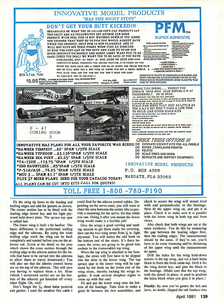
- Fit wing tip bows to leading and trailing edges and add gussets. Fit the center section with the leading edge dowel key and a light plywood hold-down plate. Add the top spruce spar last.
- Lower wing:
- Built beefier — preformed trailing edge and ailerons are the main differences.
- Use wide trailing edge stock so the wing can be built and sanded before cutting ailerons out. Carve the "bells" into the aileron trailing edges to allow downward travel as shown in the plan cross-section.
- Aileron control horns should be on the top of the ailerons (to avoid catching and damage). Include 1/16-in. sheet balsa pushrod exit guides.
- Use light flex cable for aileron control runs. Depending on your servo, sheet the area between center ribs to provide a servo mounting platform — do this while you can; after mounting the lower wing it becomes difficult.
- Wing struts and interconnection:
- Saw the two wing struts from 1/8-in. light plywood. The bottom end has an odd hook that engages a socket in the removable top wing.
- When assembling, slip the struts into slots in the lower wing first. The hook on the strut captures the top spruce spar in the lower wing, locking the wings together.
- Fitting and alignment:
- Fit and pin the lower wing to the fuselage; ensure a good fit and that the wing mounts level and perpendicular to the fuselage.
- Fit and pin the upper wing and check it is parallel with the lower wing in both top and front views.
- Check both wings are at the same incidence by measuring the gap between leading edges and then trailing edges; the measurements should match. If not, tram or shim the upper wing until they agree.
- Drill holes for wing hold-down screws in the top wing and cut a hard balsa block to fit the cabin top. Drill it for the wing dowel key and glue the block to the fuselage, ensuring screw hole alignment for correct positioning.
Final assembly and radio installation
- Final assembly sequence (recommended):
- Stabilizer
- Fin and rudder
- Lower wing
- Use epoxy for final joints to allow some working time for correct placement. Install radio gear, hook up pushrods and elevator cables. If you mounted aileron servos before gluing on the bottom wing, you'll be ahead; otherwise installation will be more difficult.
Covering and finishing
- Covering choices and tips:
- The author favored high-gloss MonoKote over silk for finish.
- Cover small parts first (wing struts, small bits) to get used to the process; you may prefer to paint struts to save time.
- Cover wings and fuselage before final assembly.
- Side windows were made from clear MonoKote and applied before the yellow overall covering.
- Fuelproofing and cowl:
- Give the engine mount area a few good coats of dope to fuel-proof it — do the inside of the cowl as well.
- The cowl was covered and then glued to the nose with epoxy; with its large openings it does not need to be removable for engine access.
- Setting dihedral:
- When covering the wings, heat-form 1/2 in. of dihedral under each wingtip:
- Shrink the bottom covering first.
- Hold the wing down at the center and block the tips up 1/2 in.
- Pass the hot iron over the top covering several times to shrink fully.
- Release the center; the wing should retain the set dihedral. Repeat if necessary and check occasionally to ensure dihedral remains.
Tips and closing
- Take your time — the model demands patience but rewards you with a striking scale appearance and good flying qualities.
- Lamination is a great technique for curved light parts. The method described (waxed corrugated cardboard forms, soaked wood, diluted glue, masking-tape clamps) yields strong, light tips and outlines.
- Double-check alignments and incidence before final gluing — nothing is sadder than a nicely built fuselage that is warped or misaligned.
- After final assembly, go over all surfaces, add or trim details as needed, then proceed to finishing and flying.
Place the tail feathers, fit the fin and rudder, check control alignment, step back and admire your craftsmanship — then get ready to fly.
Transcribed from original scans by AI. Minor OCR errors may remain.

