
Stan Powell's DOVE 650
Stan Powell
THERE ARE MANY addictive influences in our society; we read about the most common ones in daily newspapers. Little did I realize, that day in the spring of 1975, that I was about to become an "addict."
I had just finished building a workshop in my house, and I was itching to find a project. I had accompanied my wife, Sandy, to a craft shop, and while she was shopping I spied a small model airplane department on the other side of the store. You can guess what happened. When we left the store, Sandy had her goodies, and I had mine — a Top Flite Nobler kit.
Later that summer, Sandy and I made a detour on our vacation to the Southeastern Regional Championships in Winston‑Salem, NC, where we watched Les McDonald and Gene Schaffer battle it out for first place in Expert Precision Aerobatics. Boy, was I impressed! I wanted to do what they were doing so badly that my mouth watered. That was it — the "injection" that did me in — I was hooked! Since that day, Stunt flying has occupied a prominent part of my life. Fortunately, God blessed me with a perfect wife and family who have actively supported the drive to become the best. Now, I’m coming; let’s talk about the Dove 650.
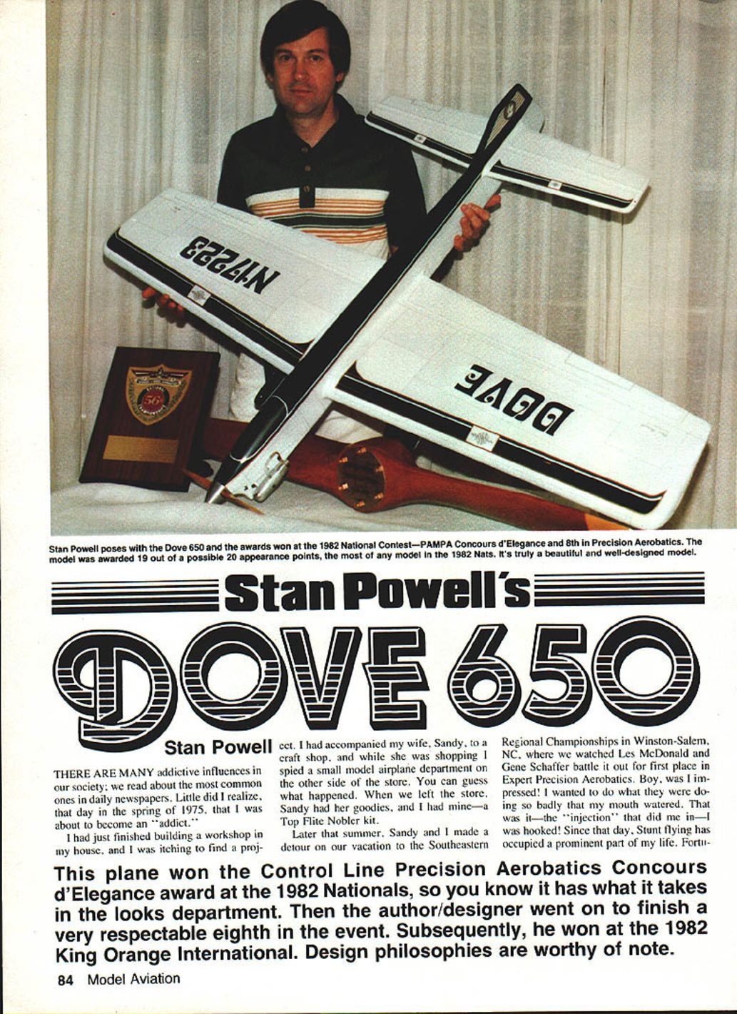
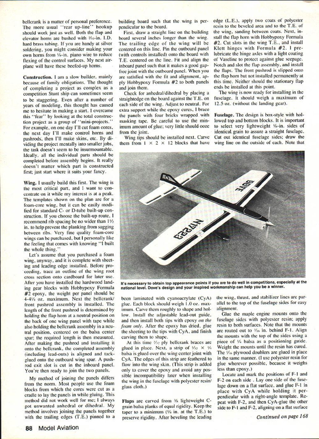
This plane won the Control Line Precision Aerobatics Concours d'Elegance award at the 1982 Nationals, so you know it has what it takes in the looks department. Then the author/designer went on to finish a very respectable eighth in the event. Subsequently, he won at the 1982 King Orange International. Design philosophies are worthy of note.
This airplane represents a composite of the best features of my previous airplanes and, of course, some borrowed ideas. The main theme in all of my airplanes has been simplicity and reliability. A competition airplane must support the flier, not be a burden to him.
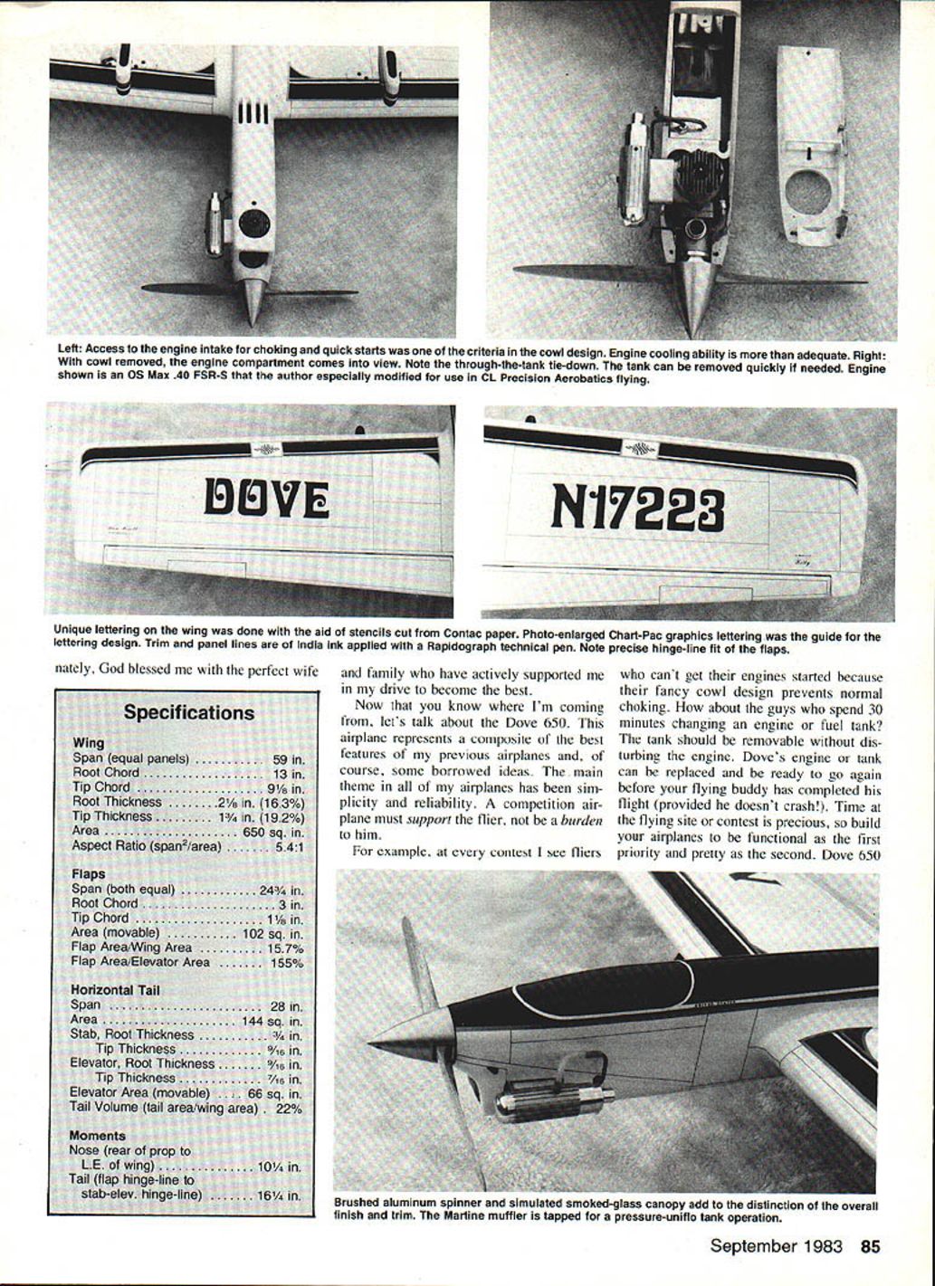
For example, at every contest I see fliers who can't get their engines started because their fancy cowl design prevents normal choking. How about the guys who spend 30 minutes changing an engine or fuel tank? The tank should be removable without disturbing the engine. Dove's engine or tank can be replaced and be ready to go again before your flying buddy has completed his flight (provided he doesn't crash!). Time at the flying site or contest is precious, so build your airplanes to be functional as the first priority and pretty as the second.
Dove 650 Specifications
Wing
- Span (equal panels) ............... 59 in.
- Root Chord ........................ 13 in.
- Tip Chord .......................... 9 1/8 in.
- Root Thickness .................... 2 1/8 in. (16.3%)
- Tip Thickness ..................... 1 3/4 in. (19.2%)
- Area .............................. 650 sq. in.
- Aspect Ratio (span^2/area) ........ 5.41
Flaps
- Span (both equal) ................. 24 3/4 in.
- Root Chord ........................ 3 in.
- Tip Chord .......................... 1 1/8 in.
- Area (movable) .................... 102 sq. in.
- Flap Area/Wing Area ............... 15.7%
- Flap Area/Elevator Area ........... 155%
Horizontal Tail
- Span .............................. 28 in.
- Area .............................. 144 sq. in.
- Stab. Root Thickness .............. 3/16 in.
- Tip Thickness ..................... 3/16 in.
- Elevator, Root Thickness .......... 9/16 in.
- Tip Thickness ..................... 7/16 in.
- Elevator Area (movable) ........... 66 sq. in.
- Tail Volume (tail area/wing area) . 22%
Moments
- Nose (rear of prop to L.E. of wing) ........ 10 1/4 in.
- Tail (flap hinge-line to stab-elev. hinge-line) . 16 1/4 in.
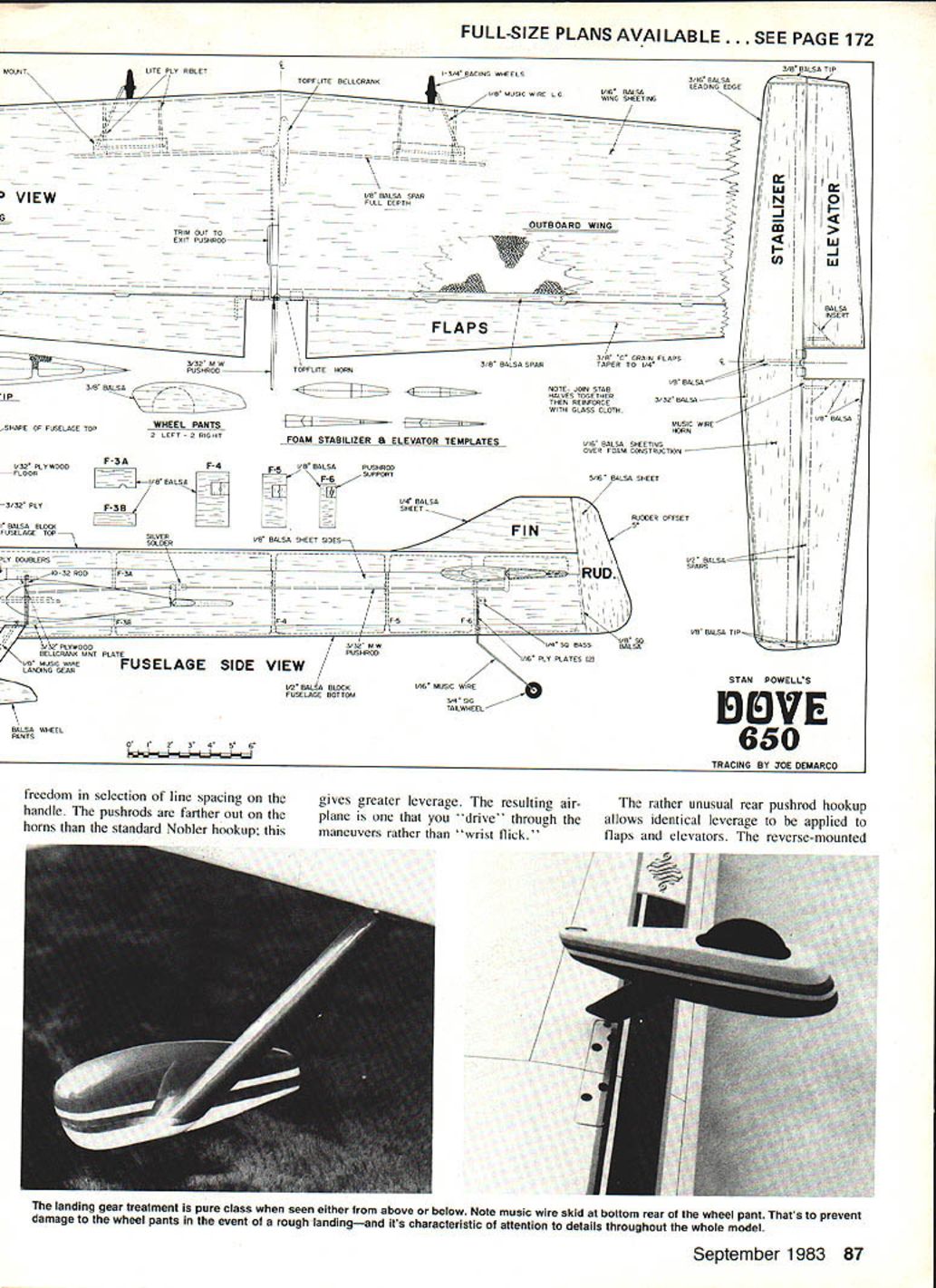
Another subtle feature of Dove's design is the landing gear. I've seen flights that I thought were great score low. Think back — what did the takeoff and landing look like? There's a better chance they weren't up to snuff. Front wheels too far rearward can really upset the way an airplane lands; too far forward will cause porpoise; too far rearward will cause bounce. Tail gear too short can cause the airplane to lift off too quickly; if it's too long it will be difficult to make a gradual, smooth lift-off. Dove's gears are optimized to give consistent 35-point takeoffs and landings.
Dove's aerodynamic proportions are a bit unusual compared with the current crop of competitive Stunters. Stunters generally have long tail moments and large tail areas for stability. The plane achieves the same effect by lengthening the nose moment instead, in combination with control surface areas and moments and a high-aspect-ratio wing. The control hook-up is designed to provide super stability yet still have the ability to turn lightning-sharp corners — as the Dove 650 at the 1982 Nats will attest to its cornering ability.
Another advantage of using a shorter tail moment is reduced weight. Build the wing, stab and elevators from foam, leaving very little margin; building errors invariably add weight. Remember, unnecessary gram weight behind the CG requires up to twice the amount of added nose weight for balance — inertia comes into play. Suppose the tail section came out too heavy — bury 2 oz. lead in the nose to balance for pitch. The airplane is still within reasonable weight limits, so you may have thought you weren't hurt. Wrong! The law of inertia roughly states that a body traveling in a straight line will continue to move along that line until a force acts upon it to change its course. The force needed is directly proportional to the mass (weight) of the moving body. That heavy nose and tail, even though balanced, will require more force to change direction. The bottom line is that you're going to need more horsepower, and you'll be demanding more of your control surfaces. It also works in reverse. Once you've got the airplane turning, particularly in a corner, it's going to take more force to change to straight flight.
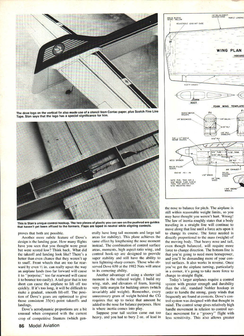
Today's larger airplanes require a control system with greater strength and durability than the old, standard Nobler hookup in order to handle the strong, gusty winds that frequently are found at contests. Dove's control system was designed with that thought in mind. The control setup gives relatively high handle movement in relation to control surface movement for a "groovy" flight with less sensitivity. This also allows greater freedom in selection of line spacing on the handle. The pushrods are farther out on the horns than the standard Nobler hookup; this gives greater leverage. The resulting airplane is one that you "drive" through the maneuvers rather than "wrist flick."
The rather unusual rear pushrod hookup allows identical leverage to be applied to flaps and elevators.
Construction
I am a slow builder, mainly because of family obligations. The thought of completing a project as complex as a competition Stunt ship can sometimes seem to be staggering. Even after a number of years of modeling, this thought has caused me to hesitate in making a start. I overcame this "fear" by looking at the total construction project as a group of "mini-projects." For example, on one day I'll cut foam cores, the next day I'll make control horns and pushrods, then I'll make skins, etc. By dividing the project mentally into smaller jobs, the task doesn't seem to be insurmountable. Ideally, all the individual parts should be completed before assembly begins. It really doesn't matter which part is constructed first; just start where it suits your fancy.
Wing
I usually build this first. The wing is the most critical part, and I want to concentrate on it while my interest is at a peak. The templates shown on the plan are for a foam-core wing, but it can be easily modified for standard C- or D-tube built-up construction. If you choose the built-up route, I recommend rib spacing be no wider than 1 1/2 in. to help prevent the planking from sagging between ribs. Very fine quality foam-core wings can be purchased, but I personally like the feeling that comes with knowing "I built the whole thing."
Let's assume that you purchased a foam wing, anyway, and it is complete with sheeting and leading edge installed. Before proceeding, trace an outline of the wing root cross section onto cardboard for later use. After you have installed the hardwood landing gear blocks with Hobbypoxy Formula #2 epoxy, the weight per panel should be 4–4 1/4 oz. maximum. Next the bellcrank/front pushrod assembly is installed. The length of the front pushrod is determined by holding the flap horn at a neutral position on the back of one wing panel with tape while also holding the bellcrank assembly in a neutral position, centered on the balsa center spar; the required length is then measured. After making the pushrod and installing it onto the bellcrank, the completed assembly (including lead-outs) is aligned and tack-glued onto the outboard wing spar. A pushrod exit slot is cut in the inboard panel. You're then ready to join the two panels.
My method of joining the panels differs from the norm. Most people use the foam blocks from which the cores were cut as a cradle to lay the panels in while gluing. This method did not work well for me; I always got unwanted anhedral or dihedral. My method involves joining the panels together with the trailing edges (T.E.) pinned to a building board such that the wing is perpendicular to the board.
First, draw a straight line on the building board several inches longer than the wing. The trailing edge of the wing will be centered on this line. Pin the outboard panel (with controls installed) onto the board with the T.E. centered on the line. Fit and align the inboard panel such that it makes a good gap-free joint with the outboard panel. When you are satisfied with the fit and alignment, apply Hobbypoxy Formula #2 to both panels and join them.
Check for anhedral/dihedral by placing a straightedge on the board against the T.E. on each side of the wing. Adjust to neutral. For extra support while the epoxy cures, I brace the panels with four bricks wrapped with masking tape. Be careful to use the minimum amount of glue; very little should ooze from the joint.
Wing tips should be installed next. Carve them from 1 x 2 x 12 blocks that have been laminated with cyanoacrylate (CyA) glue. Each block should weigh 1.0 oz. maximum. Carve them roughly to shape and hollow. Install the adjustable lead-out guide, and then install both tips with epoxy on the foam only. After the epoxy has dried, glue the sheeting to the tips with CyA, and finish carving them to shape.
At this time 1/32" ply bellcrank braces are glued in place. Next, a strip of 1/32 x 1/4 balsa is glued over the wing center joint with CyA. The edges of this strip are feathered to flow into the wing skin. (This strip is added only to cover the epoxy and avoid any possible incompatibility later when installing the wing in the fuselage with polyester resin/glass cloth.)
Flaps are carved from 3/32" lightweight C-grain balsa planks of equal rigidity. Keep the taper to a minimum (1/4 in. at the T.E.) to preserve rigidity. After beveling the leading edge (L.E.), apply two coats of polyester resin to the beveled area and to the T.E. of the wing, sanding between coats. Next, install the flap horn with Hobbypoxy Formula #2. Cut slots in the wing T.E., and install Klett hinges with Formula #2. I pre-lubricate the hinge axles with a light coating of Vaseline to protect against glue seepage. Notch and slot the flap assembly, and install the flaps. The front pushrod is slipped onto the flap horn but not installed permanently at this time. Neither should the stationary flap ends be installed at this point.
The wing is now ready for installing in the fuselage. It should weigh a maximum of 12.5 oz. (without the landing gear).
Fuselage
The design is box-style with hollowed top and bottom blocks. It is important to select very lightweight 1/8-in. sides of identical grain to assure a straight fuselage. Cut out identical fuselage sides; draw the wing line on the outside of each. Note that the wing, thrust, and stabilizer lines are parallel to the top of the fuselage sides for easy alignment.
Glue the maple engine mounts onto the fuselage sides with polyester resin; apply resin to both surfaces. Note that the mounts are routed out to 7/8 in. behind F-1. Align the mounts with the top of the sides using a piece of 1/4 balsa as a positioning guide. Weight the mounts until the resin has cured. The 1/8 plywood doublers are glued in place in the same manner. (I use polyester resin for glue wherever possible, because it weighs less than epoxy.)
Locate and mark the positions of F-1 and F-2 on each side. Lay one side of the fuselage down on a flat surface, and glue F-1 in place with CyA while holding it perpendicular with a right-angle template. Repeat with F-2, and then CyA-glue the other side to F-1 and F-2, aligning on a flat surface. (The sizes of these formers shown on the plan are nominal; they should be cut to the actual sizes that are needed.) The rest of the fuselage is relatively straightforward.
Glue the 1/2-ply tank compartment floor in place over the engine mounts, and install the blind nut for the tank hold-down. Drill the engine mount holes, and install the blind mounting nuts. Add the nose filler blocks and 1/2-in. top block insert.
A "building motor" with spinner but no cylinder is mounted on the 1/2-in. brass shims shown on the plan. Tack-glue the top block, bottom block, and cowl assembly in place, and carve the fuselage to shape (as one piece). The cowl is then removed and completed, including tie-downs, after which the top and bottom blocks are removed and hollowed. The carved and hollowed top and bottom blocks should weigh about 1-1/4–1-1/2 oz. total. Reinforce the inside of the nose and cowl with fiberglass cloth and polyester resin. Fuel-proof the entire engine compartment with several heavy coats of the resin.
The stab-elevator assembly on the original model was constructed from foam cores as shown. Lightening holes in the foam (not shown on the plan) may be cut to reduce weight. A built-up assembly will work as well. The key is strength, rigidity, and lightness. The center joint of the stab should be reinforced with glass cloth. The completed assembly should weigh 1-1/4–2.0 oz. The fin and rudder assembly can be made from very lightweight 1/4 and 3/16-in. sheet; the weight shouldn't exceed 1/4 oz.
Assembly
I advise you to reweigh the component parts before assembly to be sure they are within stated tolerances, particularly the tail section. If anything is too heavy, build it over. This is your last chance to correct any weight problem.
The first step is to install the wing in the fuselage. Draw a cross section of the wing root in the proper location on the fuselage sides, and cut out these sections. Next, remove part of the fuselage sides, at the bottom from the doublers to the T.E., to allow installation of the wing through the bottom. I use a jig to align the wing with the fuselage, as follows. Take a piece of building board about 60 inches square, and lay it on a flat surface (i.e., a table or the floor). Draw a straight line down the center of the board: the fuselage will be centered on this line. Determine where the T.E. of the wing would intersect this line, and at this point draw a line across the board perpendicular to the first line; the T.E. will be lined up along this line. Pin the fuselage top-down and centered on the fuselage line. Place the wing in the fuselage, and line up the T.E. with the T.E. line. Next, line up the centers of the L.E. and T.E. with the wing line drawn on the fuselage. Also, the vertical sides of the fuselage must be perpendicular to the wing.
Once you have the wing aligned with the fuselage in all three directions and it is pinned in place, tack-glue with CyA. Properly install the wing hold-downs (I use #4-40 screws into blind nuts). Center the wing and check dihedral, incidence, and washout. After checking, fillet the wing-fuselage joint with polyester resin and microballoons. Next install the stab. Pin the stab in place with the appropriate incidence (set on the plan), check alignment, and CyA glue. Install the fin and rudder, hinge with CA hinges, and check free movement.
Alignment is even more critical than controlling weight, so don't rush things. Fill any gaps between the wing and fuselage with soft balsa strips and CyA glue. The previously-removed fuselage bottom is now replaced, and the wing is permanently glued in place and reinforced with polyester resin and 1.5 oz/yd^2 glass cloth.
Glue in the tail-wheel gear with epoxy; brace it with balsa strips for extra strength. The bottom fuselage block is then glued back in place permanently with CyA. Carve and glue in place the inserts between the flaps and fuselage. Using these inserts as guides, tape the flaps in neutral, and glue on the stationary flap extensions. Be sure they are in a "neutral" position. Leave the flaps taped in neutral for installing the stab-elevator assembly.
Aligning an airfoil-shaped stab with a flat fuselage top can be difficult unless you have a good procedure. Mine is to build up the bottom center of the stab with balsa strips so that when the stab sits on top of the fuselage, the angle of attack is zero (parallel with the wing and top of the fuselage). Now permanently install the pushrod onto the elevator horn. Mark the position of the stab on the fuselage sides, and cut out 5/16 x 3/4-in. mounting slots. Thread the pushrod through the fuselage, and temporarily hook up the controls as shown on the plans. Line up the elevators in neutral with the stab square as seen from above and behind; pin securely in place. Check and recheck the alignment. Once you are satisfied, tack-glue the stab in place with CyA.
Remove the masking tape from the flaps, and check controls for binding. Glue the rear pushrod guides in place. Again, check for binding; the controls should be absolutely free. Solder on the pushrod retaining washer, again checking for binding. Lubricate the horn bushings.
Cut the top block in two just in front of the stab, and permanently attach the front part with CyA glue. Recheck the stab alignment; it will probably be off a little after attaching the top block. Realign the stab if necessary, and then fit and glue the rear portion of top block in place, taking care not to exert pressure on the stab. Finish gluing the stab permanently with CyA, filling any gaps with soft balsa strips. Next, align and CyA-glue the rudder/fin assembly in place. Carve and glue the inserts between the elevators and fuselage. Install the struts and wheel pants on the landing gear, being careful with alignment.
I use K&B polyester resin with Prather phenolic micro-balloons for fillers. Although a little more trouble, this system is lighter than epoxy-based fillets, and dope adheres very well. The usual techniques apply—except that pot life with this mix is short, so apply it to one area at a time. The fillets can easily be sanded to shape with 100-grit garnet paper glued on the rounded edge of a strip of 1/8-in. balsa.
Finishing
I use the traditional dope-talc-silkspan finish, which will add about 7 oz. to the weight. Start by fixing all the little "dents and dinks," and handle the airplane with "kid gloves" from here on out. I use a dope and talc paste to fill dents, then sand the airplane with 400-grit and vacuum it clean. Next, apply a coat of Aerogloss clear over the fillets and then two coats of Sig Lite-Coat over the entire airplane, sanding lightly between coats.
Cover the entire airplane with "000" silkspan using 25/75 Lite-Coat/Thinner to affix the paper. The silkspan should be slightly damp to help with wrinkle removal. After applying the silkspan, brush on a coat of Lite-Coat and then carefully sand away any overlaps in the silkspan. Brush on two more coats of Lite-Coat, and sand lightly. Brush on one coat of a mixture of 1/2 pint Lite-Coat, 1/4 pint thinner, and 2 oz. Johnson's Baby Powder. Let this dry overnight, and sand off most of this mixture with 400-grit sandpaper on a padded block. Repeat with a second sealer application if necessary.
Vacuum away any dust, and spray two mist-coats of 50/50 Lite-Coat/Thinner, followed by a mist-coat of Sig silver. The silver coat will make imperfections show up like a neon sign. After fixing any remaining flaws, spray on two mist-coats of 50/50 Lite-Coat/Thinner.
Base color and trim colors are now added. I use various combinations of Scotch Fine Line Tape and frisket material for masking. Numbering and lettering on the wing, as well as the Dove logo on the tail, are painted with the benefit of stencils cut from Contact paper. Masking flash is gently rubbed away with a damp cloth and Soft Scrub. When all of the trim color has been added, clean the entire airplane with Dupont Prep-sol and then rubbing alcohol. Apply ink lines, working on one section at a time, and then add rub-ons. You are now ready for the final clear coats.
Thin 1-1/2 qts. of Sig Lite-Coat to 45/55 dope/thinner using 70% thinner/30% Sig Retarder. Spray two coats a day (one in the morning, one in the evening) until all of the clear is applied. Let the clear "cure" for several days before you go fly it. Keep it out of direct sunlight for at least a week. After the finish has dried out for at least three weeks, wash the grease off, wet-sand to a matte finish and rub-out using Turflewax white polishing compound.
The finished weight should be in the 49–52 oz. range for best performance. Before the first flight, adjust the balance point, if necessary, so that it is 2-1/2 to 2-3/4 in. behind the leading edge of the wing. Check to make sure the outboard wing drops slowly when pivoting the airplane on the spinner and rear fuselage bottom. Mine trimmed out with 3/4 oz. of tip weight. Lead-outs should be positioned about one-third back in the slot as a starting point.
Horsepower
The "perfect" airplane will fly like a brick if you don't have a "good" engine. What's more, you won't achieve optimum trim until you have a "great" engine. It's often too difficult to distinguish between trim problems and marginal horsepower problems, particularly on a new and unfamiliar airplane. The inexperienced Stunt flier may have a real problem, because a weak engine may run perfectly. I should know; I've had my share of them.
Once you have the basic trim settings and have pitch and roll reasonably well adjusted, there are some telltale signs you can look for to spot an inadequate engine:
- Does the airplane fall to one side or the other at the top of the wingover?
- Does the airplane bobble or drop the outboard wing on hard bottom inside corners, particularly in triangles and hourglasses?
- Do you lose line tension on the top segments of the square eight?
- Does the airplane wander off course in the overhead eights?
- Do you lose line tension in the first loop of the cloverleaf?
While all of these can be related to other problems (such as trim, the wrong prop, or flying too slowly), they are more likely related to insufficient power, particularly if the airplane was built properly.
If you are going to be a SSF (Serious Stunt Flier), I'm afraid you will have to learn something about engines. I'm also sorry to say there is not an ideal out-of-the-box engine you can buy for Stunt. The closest thing available, in my opinion, is the Super Tiger .46—my recommendation to the beginner.
My frustrations with engines led me into a four-year (and continuing) study of them. I very quickly learned what made a good Stunt engine. I began experimenting. The rewards were beyond my wildest dreams. The fruit of my labor was my now-famous (infamous?) modified K&B .40s which Les McDonald used to win the last two World Championships. These engines are definitely hybrids that require extensive reworking to achieve the kind of performance I want. I am currently tinkering with the Max .40 FSR-Stunt and Max .45 FSR, both of which show great promise.
Once you have found that "great engine," make the necessary timing and combustion chamber measurements to define it. (I refer you to my article on this subject in the PAMPA Stunt News, first quarter, 1980.) Once you've done this, you can correct any deviations in your next engine.
A powerful engine can really make life easier, so don't neglect this all-important facet.
Let me conclude by listing my priorities for success at competition Stunt flying in order of importance:
- a well-designed, well-built airplane;
- a powerful engine;
- a good turbulence-free flying site;
- much practice; and
- family support.
My thanks to Les McDonald for his unbelievable support, to Dave Hemstrought for his helpful coaching and Christian fellowship, to Kent Rogers who started me out on the right track, and to Model Aviation for the opportunity to write this article. I would be pleased to help anyone who is interested in Stunt; just drop me a note:
Stan Powell 106 Jay Circle Moore, SC 29639
I also advise you to join PAMPA. Contact: Wynn Paul 1640 Maywick Drive Lexington, KY 40504
Transcribed from original scans by AI. Minor OCR errors may remain.

